

Paper Menu >>
Journal Menu >>
 Journal of Applied Mathematics and Physics, 2013, 1, 57-61 Published Online November 2013 (http://www.scirp.org/journal/jamp) http://dx.doi.org/10.4236/jamp.2013.16012 Open Access JAMP Application of Peps in Stress Analysis of Nuclear Piping Rui Liu, Zhiwei Fu, Tieping Li Nuclear and Radiation Safety Center, Ministry of Environmental Protection, Beijing, China Email: l i [email protected], [email protected] Received August 2013 ABSTRACT According to the nuclear safety regulations, this paper discusses the mechanical analysis method for piping system. Peps program has advantages of stress analysis and evaluation for nuclear piping. First, this paper introduces the Peps software, and discusses the process of stress analysis and evaluation for nuclear piping using the general finite element software; Secondly, taking nuclear class 2/3 piping system as an example, it uses Peps4.0 program to calculate the pip- ing stress in variety of working conditions, such as weight, pressure, thermal expansion, earthquake, time-histo ry force, and etc. Finally, the paper calculates the maximum stress and stress ratio according to the ASME. Keywords: Peps; Nuclear Class 2/3; Piping; ASME 1. Introduction In recent years, the rapid development of nuclear power plants has more strict demand for safety. The safety of nuclear power plants depends mainly on the devices which perform safety functions. Most of these devices are treated with radioactive medium. Once leakage oc- curs, it will result in the loss that can’t be estimated. Therefore the nuclear power plants must be designed in accordance with the corresponding regulatory require- ments. Nuclear piping which provides the important guarantee for safe operation is important equipment in nuclear reactor. The purpose of stress analysis for nuclear piping is to proof that the maximum stress does not ex- ceed the limits of regulatory requirements under different working conditions [1]. There are two kinds of methods of stress analysis for nuclear piping: simplified calculation method and nu- merical simulation method. Simplified calculation me- thod based on the empirical formula, which is suitable for small piping, could not accurately describe the me- chanical behavior of the piping system. Considering the high requirements for security, large piping systems with complex mechanical properties must resort to numerical simulation method with the aid of computer program [2]. With the development and application of computer technology, stress analysis of larger piping system can be achieved. At present, the civilian nuclear piping stress analysis software are mainly: ADLPIPE, AUTOPIPE, SYSPIPE, PIPESTRESS, KWUROHR, HROHR2, APA (AREVA PIPING ADDON), and etc. Peps (PIPE- STRESS) used in the three-dimensional linear elastic piping systems analysis and calculation at home and abroad. This paper takes a nuclear class 2/3 piping sys- tem model as an example, and uses Peps4.0 program to calculate the piping stress in variety of working condi- tions, such as weight, pressure, thermal expansion, earth- quakes time-history force, and etc. Finally the paper uses ASME standard to evaluate the mechanical properties [3-5]. 2. Peps Overview Peps of DST Company in Switzerland is an integrated package containing PIPESTRESS, the piping analysis core program, and Editpipe, its pre- and post-processor. PIPESTRESS is a program for performing linear elastic analysis of three -dimensional piping systems subject to a variety of loading conditions. Chemical process piping, nuclear and conventional power generation piping sys- tems may be investigated for compliance with piping codes and with other constraints on system response. PIPESTRESS plays an important role in the world nuc- lear industry. Editpipe is the pre- and post-processor of PIPESTRESS. Here are some outstanding features of Editpipe: 1) Advanced text editor environment with full syntax coloring for editing PIPESTRESS free format input files. 2) Instant visualization of the piping model defined in the input file, with input error detection. 3) Integrated database of PIPESTRESS free format input cards and standard piping fittings. 4) Post-processing module for visualizing mode shapes and load case dis- placements, forces and moments. 5) Tabular view of the data. 6) QuickPipe wizard to generate complete input 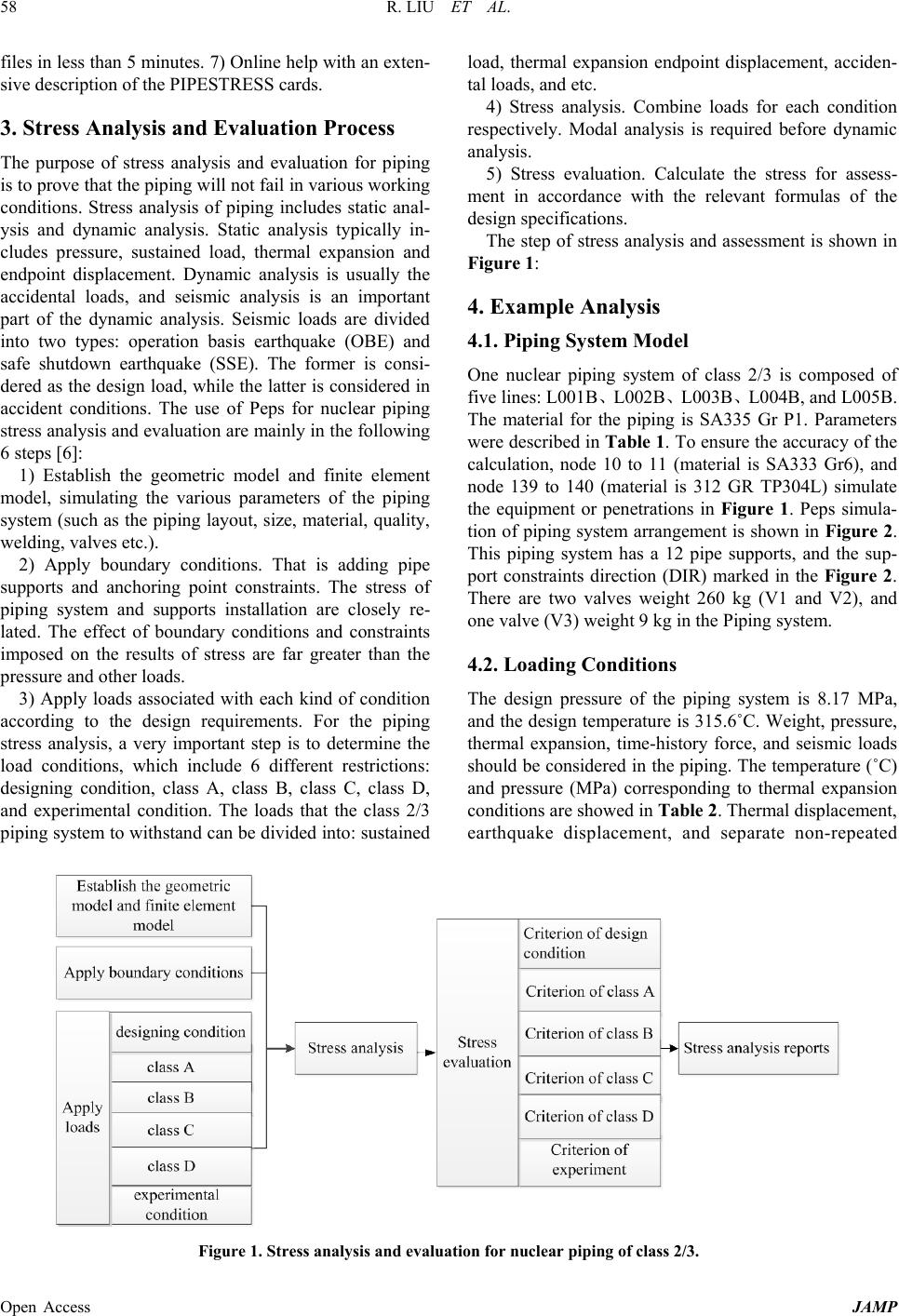 R. LIU ET AL. Open Access JAMP 58 files in less than 5 minutes. 7) Online help with an exten- sive description of the PIPESTRESS cards. 3. Stress Analysis and Evaluation Process The purpose of stress analysis and evaluation for piping is to prove that the piping will not fail in various working conditions. Stress analysis of piping includes static anal- ysis and dynamic analysis. Static analysis typically in- cludes pressure, sustained load, thermal expansion and endpoint displacement. Dynamic analysis is usually the accidental loads, and seismic analysis is an important part of the dynamic analysis. Seismic loads are divided into two types: operation basis earthquake (OBE) and safe shutdown earthquake (SSE). The former is consi- dered as the design load, while the latter is considered in accident conditions. The use of Peps for nuclear piping stress analysis and evaluation ar e mainly in the following 6 steps [6] : 1) Establish the geometric model and finite element model, simulating the various parameters of the piping system (such as the piping layout, size, material, quality, welding, valves etc.). 2) Apply boundary conditions. That is adding pipe supports and anchoring point constraints. The stress of piping system and supports installation are closely re- lated. The effect of boundary conditions and constraints imposed on the results of stress are far greater than the pressure and other loads. 3) Apply loads associated with each kind of condition according to the design requirements. For the piping stress analysis, a very important step is to determine the load conditions, which include 6 different restrictions: designing condition, class A, class B, class C, class D, and experimental condition. The loads that the class 2/3 piping system to withs tand can be divided into: sustained load, thermal expansion endpoint displacement, acciden- tal loads, and etc. 4) Stress analysis. Combine loads for each condition respectively. Modal analysis is required before dynamic analysis. 5) Stress evaluation. Calculate the stress for assess- ment in accordance with the relevant formulas of the design specifications. The step of stress analysis and assessment is shown in Figure 1: 4. Example Analysis 4.1. Piping System Model One nuclear piping system of class 2/3 is composed of five lines: L001B、L002B、L003B、L004B, and L005B. The material for the piping is SA335 Gr P1. Parameters wer e descr ibed in Table 1. To ensure the accuracy of the calculation, node 10 to 11 (material is SA333 Gr6), and node 139 to 140 (material is 312 GR TP304L) simulate the equipment or penetrations in Figure 1. Peps simula- tion of piping system arrangement is shown in Figure 2. This piping system has a 12 pipe supports, and the sup- port constraints direction (DIR) marked in the Figure 2. There are two valves weight 260 kg (V1 and V2), and one valve (V3) weight 9 kg in the Piping sys te m. 4.2. Lo ading Conditions The design pressure of the piping system is 8.17 MPa, and the design temperature is 315.6˚C. Weight, pressure, thermal expansion, time-history force, and seismic loads should be considered in the piping. The temperature (˚C) and pressure (MPa) corresponding to thermal expansion conditions are showed in Table 2. Thermal displacement, earthquake displacement, and separate non-repeated Figure 1. Stress analysis and evaluation for nuclear piping of class 2/3. 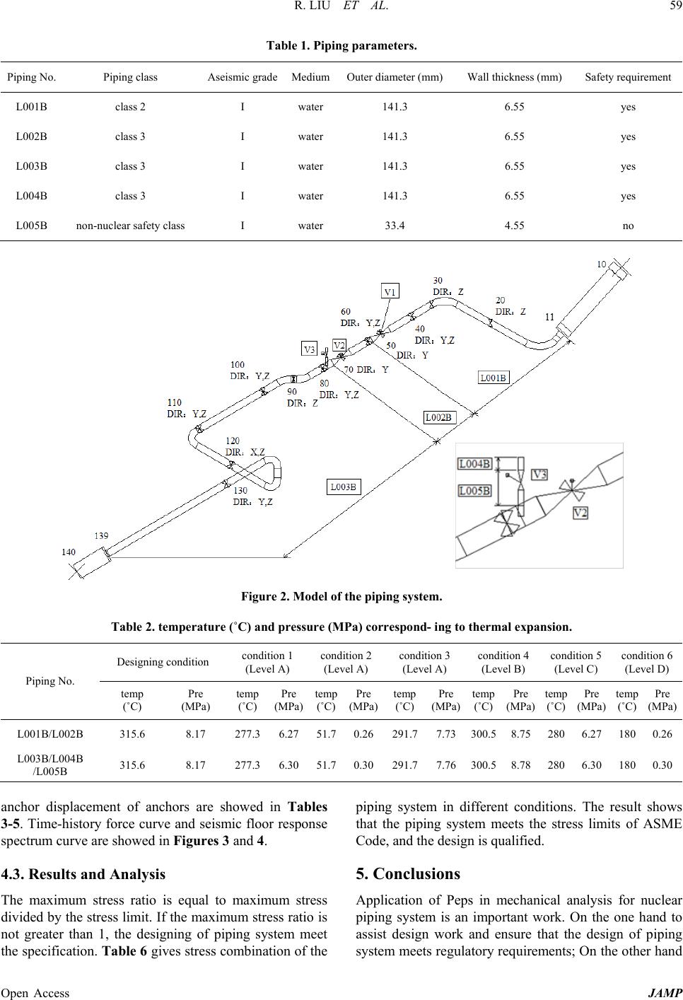 R. LIU ET AL. Open Access JAMP 59 Table 1. Piping parameters. Piping No. Piping class Aseismic grade Medium Outer diameter (mm) Wall thickness (mm) Safety requirement L001B class 2 I water 141.3 6.55 yes L002B class 3 I water 141.3 6.55 yes L003B class 3 I water 141.3 6.55 yes L004B class 3 I water 141.3 6.55 yes L005B non-nuclear safety class I water 33.4 4.55 no Figure 2. Model of the piping system. Table 2. temperature (˚C) and pressure (MPa) correspond- ing to thermal expansion. Piping No. Designing condition condition 1 (Level A) condition 2 (Level A) condition 3 (Level A) condition 4 (Level B) condition 5 (Level C) condition 6 (Level D) temp (˚C) Pre (MPa) temp (˚C) Pre (MPa) temp (˚C) Pre (MPa) temp (˚C) Pre (MPa) temp (˚C) Pre (MPa) temp (˚C) Pre (MPa) temp (˚C) Pre (MPa) L001B/L002B 315.6 8.17 277.3 6.27 51.7 0.26 291.7 7.73 300.5 8.75 280 6.27 180 0.26 L003B/L004B /L005B 315.6 8.17 277.3 6.30 51.7 0.30 291.7 7.76 300.5 8.78 280 6.30 180 0.30 anchor displacement of anchors are showed in Tables 3-5. Time -history force curve and seismic floor response spectrum curve are showed in Figures 3 and 4. 4.3. Results and Analysis The maximum stress ratio is equal to maximum stress divided by the stress limit. If the maximum stress ratio is not greater than 1, the designing of piping system meet the specification. Table 6 gives stress combination of the piping system in different conditions. The result shows that the piping system meets the stress limits of ASME Code, and the design is qualified. 5. Conclusions Application of Peps in mechanical analysis for nuclear piping system is an important work. On the one hand to assist design work and ensure that the design of piping system meets regulatory requirements; On the other hand 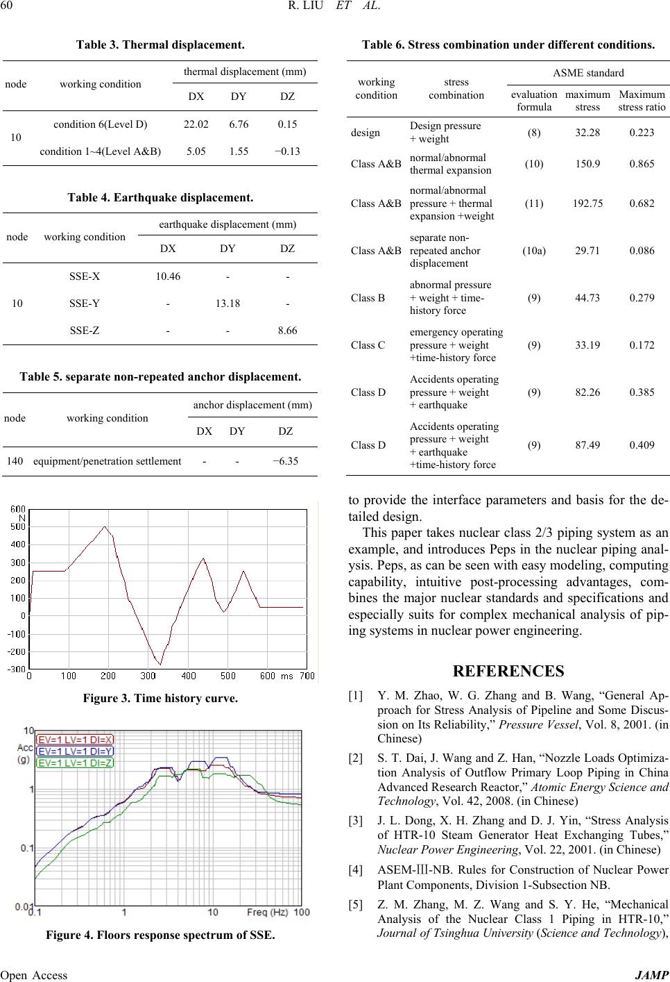 R. LIU ET AL. Open Access JAMP 60 Table 3. Thermal displacement. node working condition thermal displacement (mm) DX DY DZ 10 condition 6(Level D) 22.02 6.76 0.15 condition 1~4( Level A&B) 5.05 1.55 −0.13 Table 4. Earthquake displaceme nt. node working condition earthquake displacement (mm) DX DY DZ 10 SSE-X 10.46 - - SSE-Y - 13.18 - SSE-Z - - 8.66 Table 5. separate non-repeated anchor displacement. node working condition anchor displacement (mm) DX DY DZ 140 equipment/penetration settlement - - −6.35 Figure 3. Time history curve. Figure 4. Floors response spectrum of SSE. Table 6. Stress combination under different conditions. working condition stress combination ASME standard evaluation formula maximum stress Maximum stress ratio design Design pressure + weight (8) 32.28 0.223 Class A&B normal/abnormal thermal expansion (10) 150.9 0.865 Class A&B normal/abnormal pressure + thermal expansion +weight (11) 192.75 0.682 Class A&B separate non- repeated anchor displacement (10a) 29.71 0.086 Class B abnormal pressure + weight + time- history force (9) 44.73 0.279 Class C em ergency operating pressure + weight +time-history force (9) 33.19 0.172 Class D Accidents operating pressure + weight + earthquake (9) 82.26 0.385 Class D Accidents operating pressure + weight + earthquake +time-history force (9) 87.49 0.409 to provide the interface parameters and basis for the de- tailed design. This paper takes nuclear class 2/3 piping system as an example, and introduces Peps in the nuclear piping anal- ysis. Peps, as can be seen with easy modeling, computing capability, intuitive post-processing advantages, com- bines the major nuclear standards and specifications and especially suits for complex mechanical analysis of pip- ing syst ems in nucle ar power e ngineering. REFERENCES [1] Y. M. Zhao, W. G. Zhang and B. Wang, “General Ap- proach for Stress Analysis of Pipeline and Some Discus- sion on Its Reliability,” Pressure Vessel, Vol. 8, 2001. (in Chinese) [2] S. T. Dai, J. Wang and Z. Han, “Nozzle Loads Optimiza- tion Analysis of Outflow Primary Loop Piping in China Advanced Research Reactor,” Atomic Energy Science and Technology, Vol. 42, 2008. (in Chinese) [3] J. L. Dong, X. H. Zhang and D. J. Yin, “Stress Analysis of HTR-10 Steam Generator Heat Exchanging Tubes,” Nuclear Power Engineering, Vol. 22, 2001. (in Chinese) [4] ASEM-Ⅲ-NB. Rules for Construction of Nuclear Power Plant Components, Division 1-Subsection NB. [5] Z. M. Zhang, M. Z. Wang and S. Y. He, “Mechanical Analysis of the Nuclear Class 1 Piping in HTR-10,” Journal of Tsingh ua Univ ersity (Science and Technology),  R. LIU ET AL. Open Access JAMP 61 Vol. 40, 2000. (in Chinese) [6] Q. Mao, W. Wang and Y. X. Zhang, “The Stress Analy sis Evaluation and Pipe Support Layout for Pres Surizer Dis- change System,” Nuclear Power Engineering, Vol. 21, 2000. (in Chinese) |