

Paper Menu >>
Journal Menu >>
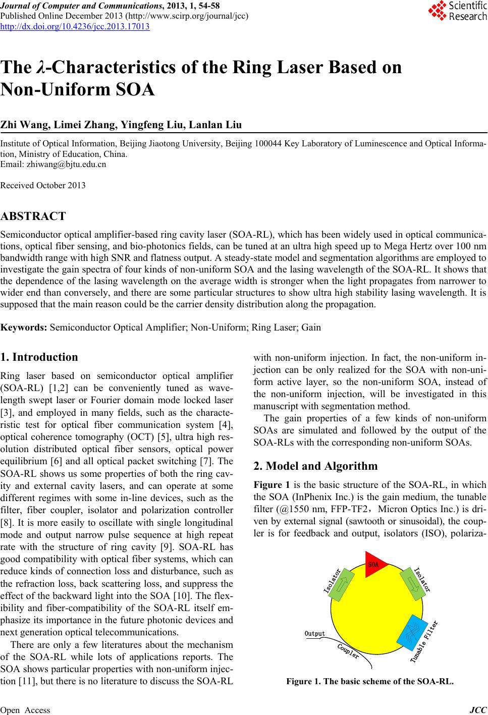 Journal of Computer and Communications, 2013, 1, 54-58 Published Online December 2013 (http://www.scirp.org/journal/jcc) http://dx.doi.org/10.4236/jcc.2013.17013 Open Access JCC The λ-Characteristics of the Ring Laser Based on Non-Uniform SOA Zhi Wang, Limei Zhang, Yingfeng Liu, Lanlan Liu Institute of Optical Information, Beijing Jiaotong University, Beijing 100044 Key Laboratory of Luminescence and Optical Informa- tion, Ministry of Education, China. Email: [email protected] Received October 2013 ABSTRACT Semiconductor optical amplifier -based ring cavity laser (SOA -RL), which has been widely used in optical communica- tions, optical fiber sensing, and bio-photonics fields, can be tuned at an ultra high speed up to Mega Hertz over 100 nm bandwidth r ange with high SNR and flatness output. A steady-state model and segmentation algorithms are employed to investigate the gain spectra of four kinds of non-uniform SOA and the lasing wavelength of the SOA-RL. It shows that the dependence of the lasing wavelength on the average width is stronger when the light propagates from narrower to wider end than conversely, and there are some particular structures to show ultra high stability lasing wavelength. It is supposed that the main reason could be the carrier density distribution along the propagation. Keywords: Semiconductor Optical Amplifier; Non-Uniform; Ring Laser; Gain 1. Introduction Ring laser based on semiconductor optical amplifier (SOA-RL) [1,2] can be conveniently tuned as wave- length swept laser or Fourier domain mode locked laser [3], and employed in many fields, such as the characte- ristic test for optical fiber communication system [4], optical coherence tomography (OCT) [5], ultra high res- olution distributed optical fiber sensors, optical power equilibrium [6] and all optical packet switching [7]. The SOA-RL shows us some properties of both the ring cav- ity and external cavity lasers, and can operate at some different regimes with some in-line devices, such as the filter, fiber coupler, isolator and polarization controller [8]. It is more easily to oscillate with single longitudinal mode and output narrow pulse sequence at high repeat rate with the structure of ring cavity [9]. SOA-RL has good compatibility with optical fiber systems, which can reduce kinds of connection loss and disturbance, such as the refraction loss, back scattering loss, and suppress the effect of the backward light into the SOA [10]. The flex- ibility and fiber-compatibility of the SOA-RL itself em- phasize its importance in the future photonic devices and next generation optical telecommunications. There are only a few literatures about the mechanism of the SOA-RL while lots of applications reports. The SOA shows particular prop erties with non-uniform injec- tion [11], but there is no literature to discuss the SOA-RL with non-uniform injection. In fact, the non-uniform in- jection can be only realized for the SOA with non-uni- form active layer, so the non-uniform SOA, instead of the non-uniform injection, will be investigated in this manuscript with segmentation method. The gain properties of a few kinds of non-uniform SOAs are simulated and followed by the output of the SOA-RLs with the corresponding non-uniform SOAs. 2. Model and Algorithm Figure 1 is the basic structure of the SOA-RL, in which the SOA (InPhenix Inc.) is the gain medium, the tunable filter (@1550 nm, FFP-TF2,Micron Optics Inc.) is dri- ven by external signal (sawtooth or sinusoidal), the coup- ler is for feedback and output, isolators (ISO), polariza- Isolator Tunable Filter SOA Coupler Isolator Output Figure 1. The basic scheme of the SOA-RL. 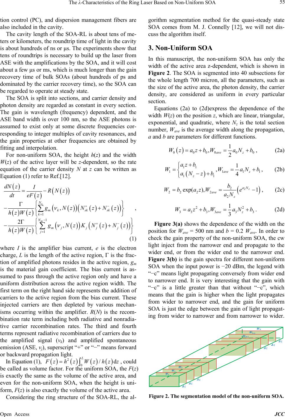 The λ-Characteristics of the Ring Laser Based on Non-Uniform SOA Open Access JCC 55 tion control (PC), and dispersion management fibers are also included in the cavity. The cavity length of the SOA-RL is about tens of me- ters or kilometers, the ro undtrip time of light in the cavity is about hundreds of ns or μs. The experiments show that tens of roundtrips is necessary to build up the laser from ASE with the amplifications by the SOA, and it will cost about a few μs or ms, which is much longer than the gain recovery time of bulk SOAs (about hundreds of ps and dominated by the carrier recovery time), so the SOA can be regarded to operate at steady state. The SOA is split into sections, and carrier density and photon density are regarded as constant in every section. The gain is wavelength (frequency) dependent, and the ASE band width is over 100 nm, so the ASE photons is assumed to exist only at some discrete frequencies cor- responding to integer multiples of cavity resonances, and the gain properties at other frequencies are obtained by fitting and interpolation. For non-uniform SOA, the height h(z) and the width W(z) of the active layer will be z-dependent, so the rate equation of the carrier density N at z can be written as Equation (1) refer to Ref.[12]. ( ) ( )( ) ( ) ( )( )( ) ( ) ( )( ) ( ) ( )( )( ) ( ) ( )( ) ( ) 1 1 1 , 2, s m N m ksksk k N mjj jj j dN zIRNz dteF z g NzNzNz hzWz gNz KNzNz hzWz ν ν +− = −+− = = − Γ −+ Γ −+ ∑ ∑ , (1) where I is the amplifier bias current, e is the electron charge, L is the length of the active region, Γ is the frac- tion of amplified photons resides in the active region, gm is the material gain coefficient. The bias current is as- sumed to pass through the active region only and have a uniform distribution across the active region width. The first term on the right hand side represents the addition of carriers to the active region from the bias current. These injected carriers are then depleted by various mechan- isms occurring within the amplifier. R(N) is the recom- bination rate term including both radiative and nonradia- tive carrier recombination rates. The third and fourth terms represent radiative recombination of carriers due to the amplified signal (νk) and amplified spontaneous emission (ASE, νj), superscript “+” or “−” means forw ard or backward propagation light. In Equation (1), ( )( )( )( ) 2 0 /d L Fzh zWzhz z= ∫ , could be called as volume factor. For the uniform SOA, the F(z) is exactly the same as the volume of the active area, and even for the non-uniform SOA, when the height is uni- form, F(z) is also exactly the volume of the active area. Considering the ring structure of the SOA-RL, the al- gorithm segmentation method for the quasi-steady state SOA comes from M. J. Connelly [12], we will not dis- cuss the algorithm itself. 3. Non-Uniform SOA In this manuscript, the non-uniform SOA has only the width of the active area z-dependent, which is shown in Figure 2. The SOA is segmented into 40 subsections for the whole length 700 micron, all the parameters, such as the size of the active area, the photon density, the carrier density, are considered as uniform in every particular section. Equations (2a) to (2d)express the dependence of the width W(z) on the position z, which are linear, triangular, exponential, and quadratic, where Nz is the total section number, Wave is the average width along the propagation, a and b are parameters for different functions. ( ) 00 0000 1 ,2 ave z Wzazb WaNb=+=+ , (2a) ( ) 11 11 11 11 1 ,4 ave z z az b WWaN b aNz b + == + −+ , (2b) ( ) 2 2 222 22 exp( ),1 z aN ave z b Wbaz We aN ==− , (2c) 22 3 33333 1 ,3 ave z WazbWaNb=+=+ . (2d) Figure 3(a) shows the dependence of the width on the position for Wave = 500 nm and b = 0.2 Wave. In order to check the gain property of the non-uniform SOA, the cw light inject from the narrower end and propagate to the wider end, or from the wider end to the narrower end. Figure 3(b) is the gain spectra for different non-uniform SOA when the input power is −20 dBm, the legend with “−c” means light propagating conversely from wider end to narrower end. It is very interesting that the gain with “−c” is a little greater than that without “−c”, which means that the gain is higher when the light propagates from wider to narrower end, and the gain for uniform SOA is just the edge between the gain of light propagat- ing from wider to narrower and from narrower to wider. Δ z W 1 Δ z W 2 Δ z W 3 Δ z W N-2 Δ z W N-1 Δ z W N Figure 2. The segmentation model of the non-uniform SOA. 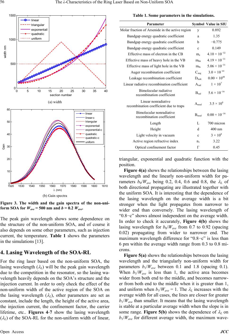 The λ-Characteristics of the Ring Laser Based on Non-Uniform SOA Open Access JCC 56 (a) width (b) Gain spectra Figure 3. The width and the gain spectra of the non-uni- form SOA for Wave = 500 nm and b = 0.2 Wave. The peak gain wavelength shows some dependence on the structure of the non-uniform SOA, and of course it also depends on some other parameters, such as injection current, the temperature. Table 1 shows the parameters in the simulations [13]. 4. Lasing Wavelength of the SOA-RL For the ring laser based on the non-uniform SOA, the lasing wavelength ( λ L) will be the peak gain wavelength due to the competition in the resonator, so the lasing wa- velength heavily depends on the SOA’s structure and the injection current. In order to only check the effect of the non-uniform width of the active region of the SOA on the lasing wavelength ( λ L), other parameters are set as constant, include the length, the height of the active area, the injection current, the confinement factor, the carrier lifetime, etc.. Figures 4-7 show the lasing wavelength ( λ L) of the SOA-RL for the non-uniform width of linear, Table 1. Some parameters in the simulations. Parameter Symbol Value in SIU Molar fraction of Arsenide in the active region y 0.892 Bandgap energy quadratic coefficient a 1.35 Bandgap energy quadratic coefficient b −0.775 Bandgap energy quadratic coefficient c 0.149 Effective mass of electron in the CB me 4.10 × 10⁻³² Effective mass of heavy hole in the VB mhh 4.19 × 10⁻³¹ Effective mass of light hole in the VB mlh 5.06 × 10⁻³¹ Auger recombination coefficient Caug 3.0 × 10−41 Leakage recombination coefficient Dleak 0. 00 × 1048 Linear radiative recombination coefficient Arad 1 × 10⁷ Bimolecular radiative recombination coefficient Brad 5.6 × 10⁻¹⁶ Linear nonradiative recombination coefficient due to traps Anrad 3.5 × 10⁸ Bimolecular nonradiative recombination coefficient Bnrad 0.00 × 10⁻¹⁶ Length L 700 micr on Height d 400 nm Light velocity in vacuum c 3 × 10⁸ Active region refractive index n1 3.22 Optical confinement factor Γ 0.45 triangular, exponential and quadratic function with the position. Figure 4(a) shows the relationships between the lasing wavelength and the linearly non-uniform width for pa- rameters b0/Wave being 0.2, 0.4, 0.6 and 0.8, the λ L of both directional propagating are illustrated together with the uniform SOA. It is interesting that the dependence of the lasing wavelength on the average width is a bit stronger when the light propagates from narrower to wider end than conversely. The lasing wavelength of “0.8−c” shows almost independent on the average width. In order to check it accurately, Figure 4(b) shows the lasing wavelength for b0/Wave from 0.7 to 0.92 (spacing 0.02) propagating from wider to narrower end. The maximum wavelength difference for “0.8−c” is less than 6 pm within the average width range from 0.3 to 0.8 mi- crons. Figure 5(a) shows the relationships between the lasing wavelength and the triangularly non-uniform width for parameters b1/Wave between 0.1 and 1.8 (spacing 0.1). When b1/Wave is less than 1, the active area becomes wider from both end to the middle, and becomes narrow- er from both end to the middle when it is greater than 1, and uniform when b1/Wave = 1. The λ L increases with the average width for all cases, the lines are closer for greater b1/Wave than smaller. It means that the lasing wavelength is stable at a particular average width when the slope is in some range. Figure 5(b) shows the dependence of λ L on b1/Wave for different average width, the maximum wave- 0510 1520 2530 3540 0 500 1000 1500 s ecti on num ber widt h nm linear t riangul ar exponentail quadrat ic uniform 1520 1530 1540 1550 1560 1570 1580 1590 1600 1610 0 10 20 30 40 50 60 λ (nm ) Gain li near li near-c t ri angular ex ponentail ex ponential-c quadratic quadratic-c uniform 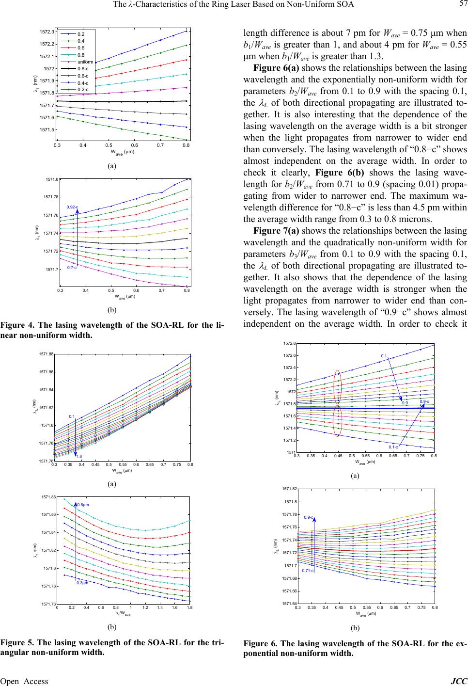 The λ-Characteristics of the Ring Laser Based on Non-Uniform SOA Open Access JCC 57 (a) (b) Figure 4. The lasing wavelength of the SOA-RL for the li- near non-uniform width. (a) (b) Figure 5. The lasing wavelength of the SOA-RL for the tri- angular non-uniform width. length difference is about 7 pm for Wave = 0.75 μm when b1/Wave is greater than 1, and about 4 pm for Wave = 0.55 μm when b1/Wave is greater than 1.3. Figure 6(a) shows the relationships between the lasing wavelength and the exponentially non-uniform width for parameters b2/Wave from 0.1 to 0.9 with the spacing 0.1, the λ L of both directional propagating are illustrated to- gether. It is also interesting that the dependence of the lasing wavelength on the average width is a bit stronger when the light propagates from narrower to wider end than conversely. The lasing wavelength of “0.8−c” shows almost independent on the average width. In order to check it clearly, Figure 6(b) shows the lasing wave- length for b2/Wave from 0.71 to 0.9 (spacing 0.01) propa- gating from wider to narrower end. The maximum wa- velength difference for “0. 8−c” is less than 4.5 pm within the average width range from 0.3 to 0.8 microns. Figure 7(a) shows the relationships between the lasing wavelength and the quadratically non-uniform width for parameters b3/Wave from 0.1 to 0.9 with the spacing 0.1, the λ L of both directional propagating are illustrated to- gether. It also shows that the dependence of the lasing wavelength on the average width is stronger when the light propagates from narrower to wider end than con- versely. The lasing wavelength of “0.9−c” shows almost independent on the average width. In order to check it (a) (b) Figure 6. The lasing wavelength of the SOA-RL for the ex- ponential non -uniform width. 0.3 0.4 0.5 0.6 0.7 0.8 1571.5 1571.6 1571.7 1571.8 1571.9 1572 1572.1 1572.2 1572.3 Wave ( µ m) λ L (nm) 0.2 0.4 0.6 0.8 uniform 0.8-c 0.6-c 0.4-c 0.2-c 0.3 0.4 0.5 0.6 0.7 0.8 1571.7 1571.72 1571.74 1571.76 1571.78 1571.8 λ L (nm) W ave ( µ m) 0.92-c 0.7-c 0.3 0.35 0.4 0.45 0.5 0.55 0.6 0.65 0.7 0.75 0.8 1571.76 1571.78 1571.8 1571.82 1571.84 1571.86 1571.88 W ave ( µ m) λ L (nm) 1.8 0.1 00.2 0.4 0.6 0.811.2 1.4 1.61.8 1571.76 1571.78 1571.8 1571.82 1571.84 1571.86 1571.88 b 1 /W ave λ L (nm) 0.8 µ m 0.3 µ m 0.30.35 0.4 0.450.5 0.550.6 0.650.7 0.75 0.8 1571 1571.2 1571.4 1571.6 1571.8 1572 1572.2 1572.4 1572.6 1572.8 W ave ( µ m) λ L (nm) 0.1-c 0.1 0.9 0.9-c 0.30.35 0.4 0.45 0.50.55 0.60.65 0.70.750.8 1571.64 1571.66 1571.68 1571.7 1571.72 1571.74 1571.76 1571.78 1571.8 1571.82 W ave ( µ m) λ L (nm) 0.71-c 0.9-c  The λ-Characteristics of the Ring Laser Based on Non-Uniform SOA Open Access JCC 58 (a) (b) Figure 7. The lasing wavelength of the SOA-RL for the qu- adratic non-uniform width. clearly, Figure 7(b) shows the lasing wavelength for b3/Wave from 0.8 to 0.95 (spacing 0.01) propagating from wider to narrower end. The maximum wavelength dif- ference for “0.8−c” is less than 6.8 pm within the average width range from 0.3 to 0.8 microns. 5. Discussion and Conclusion The gain property for a fe w kind of non-uniform SOA is simulated, and the lasing wavelength of the ring cavity laser with the non-uniform SOA is investigated with the dependence on the active area width and the non-uni- formity. It shows that the dependence of the lasing wave- length on the average width is stronger when the light propagates from narrower to wider end than conversely. It is supposed that the main reason could be the carrier density distribution along the propagation. 6. Acknowledgements This work was supported in part by the National Natural Science Foundation of China under grant 61077048, Bei- jing Natural Science Foundation under grant 4132035, Specialized Research Fund for the Doctoral Program of Higher Education under grant 20120009110032, and by Beijing Ji a otong University under grant 2012J B M103. REFERENCES [1] Y. Liu, M. T. Hill, N. Calabretta, H. dewaardt, G. D. Khoe, Fellow and H. J. S. Dorren, “Three-State All-Opt- ical Memory Based on Coupled ring Lasers,” IEEE Pho- ton. Technol. Lett., Vol. 15, No. 10, 2003, pp. 1461-1464. http://dx.doi.org/10.1109/LPT.2003.818221 [2] Q. F. Xu and M. Y. Yao, “Theoretical Analyses on Short- Term Stability of Semiconductor Fiber Ring Lasers,” IEEE Journal of Quantum Electr on, Vol. 39, No. 10, 2003, pp. 960-965. [3] H. X. Chen, “Multiwavelength Fiber Ring Lasing by Use of a Semiconductor Optical Amplifier,” Optics Letters, Vol. 30, No. 6, 2005, pp. 619-621. http://dx.doi.org/10.1364/OL.30.000619 [4] L. T. Wang, N. A. Fang, Y. W a ng a nd Z. M. Huang, “Dual- Channel PolSK Optical Transmissions Using SOA-Based All-Optical Polarization Modulations,” Acta Optica Sini- ca, Vol. 29, No. 1, 2009, pp. 138-144. http://dx.doi.org/10.3788/AOS20092901.0138 [5] S. R. Chinn, E. A. Swanson, and J. G. Fujimoto, “Optical Coherence Tomography Using a Frequency Tunable Op- tical Source,” Optics Letters, Vol. 22, No. 5, 1997, pp. 340-342. http://dx.doi.org/10.1364/OL.22.000340 [6] J. Leuthold and M. Kauer, “Power Equalisation and Sig- nal Regeneration with Delay Interferometer All-Optical Wavelength Converters,” Electronics Letters, Vol. 38, No. 24, 2002, pp. 1567-1568. http://dx.doi.org/10.1049/el:20021077 [7] C. Habib, V. Baby, L. R. Chen, A. Delisle-Simard and S. LaRoehelle, “All-Optical Swapping of Spectral Ampli- tude Code Labels Using Nonlinear Media And Semicon- ductor Fiber Ring Lasers,” IEEE Journal of Selected To- pics in Quantum Electronics, Vol. 14, No. 3, 2008, pp. 879-888. http://dx.doi.org/10.1109/JSTQE.2008.918047 [8] P. Wei, “Fiber Ring Cavity Semiconductor Laser of Re- search,” Ph.D. Thesis, Southwest Jiaotong University, Chengdu, 2000. [9] M. Schell and E. Schol, “Time-Dependent Simulation of a Semiconductor Laser Amplifier: Pulse Compression in a Ring Configuration and Dynamic Optical Bistability,” IEEE Journal of Quantum Electronics, Vol. 26, No. 6, 1990, pp. 1005-1013. http://dx.doi.org/10.1109/3.108096 [10] L. F. Stokes, M. Chodorow and H. J. Shaw, “All-Single- Mode Fiber Resonator,” Optics Letters, Vol. 7, No. 6, 1982, pp. 288-290. http://dx.doi.org/10.1364/OL.7.000288 [11] H. Taleb, K. Abedi and S. Golmohammadi, “Operation of Quantum-Dot Semiconductor Optical Amplifiers under Nonuniform Current Injection,” Applied Optics, Vol. 50, No. 5, 2011, pp. 608-617. http://dx.doi.org/10.1364/AO.50.000608 [12] M. J. Connelly, “Wideband Semiconductor Optical Am- plifier Steady-State Numerical Model,” IEEE Journal of Quantum Electronics, Vol. 37, No. 3, 2001, pp. 439-448. http://dx.doi.org/10.1109/3.910455 0.30.35 0.40.45 0.50.55 0.60.65 0.70.75 0.8 1571 1571.2 1571.4 1571.6 1571.8 1572 1572.2 1572.4 1572.6 1572.8 W ave ( µ m) λ L (nm) 0.9 0.9-c 0.1 0.1-c 0.3 0.35 0.4 0.45 0.5 0.55 0.6 0.65 0.7 0.75 0. 8 1571.68 1571.7 1571.72 1571.74 1571.76 1571.78 1571.8 W ave ( µ m) λ L (nm) 0.95-c 0.8-c |