

Paper Menu >>
Journal Menu >>
 Journal of Geoscience and Environment Protection 2013. Vol.1, No.3, 1-6 Published Online December 2013 in SciRes (http://www.scirp.org/journal/gep) http://dx.doi.org/10.4236/gep.2013.13001 Open Access 1 Characterization of Hydraulic Behaviours of Coarse Rock Materials in a Large Permeameter Farzad Ferdos1, James Yang1,2, Anders Wörman1 1Hydraulic Engineering, Royal Institute of Technology (KTH), Stockholm, Sweden 2Principal Engineer, Vattenfall Research and Development (R&D), Älvkarleby, Sweden Email: [email protected] Received August 2013 The hydraulic behaviour of a rock material structure is a major feature for its design and safety assess- ment. Similar to all other physical problems, in order to enclose the governing equations systems and achieve a solution, the hydraulic characteristics of these materials need to be determined experimentally and implemented then into adopted thermo-dynamical models. This paper covers the process of the design, construction and operation of an experimental rig built for this specific purpose. Using the constructed large-scale permeameter, tests have been conducted. The non-linear hydraulic behaviour of various mate- rials under extreme turbulent conditions, where Reynolds number reaches unprecedented values, has not been studied before. Preliminary results are presented and discussed. Keywords: Experimental Study; Permeameter; Coarse Rock Material; Turbulent Flo w; Reynol ds Number Introduction Rock materials are used in constructing a wide range of in- frastructures that have interaction with water. These structures are used to control and manipulate water flow as well as to provide water retention. The structural behaviour of these structures is directly dependent on the interactions between the granules and the flowing fluid through them. Therefore, in or- der to calculate any structural response, a comprehensive un- derstanding of hydraulic behaviour is needed. Among these structures, embankment dams (rock-fill dams and downstream zone of earth-fill dams) draw a lot of attention and many safety recommendations and guidelines are continuously developed nationwide to ensure the safety of these structures. This level of attention is given to dams since they are massive infrastructures built mostly of rock fill material and the consequences of their failure could prove catastrophic both socially and economically (ICOLD, 1987). The equation most commonly used to describe the flow of a fluid through a porous medium is Darcy’s law, in which the flow is expressed as a linear relation between the head loss and the fluid velocity, proportioned by hydraulic conductivity as the media’s property, where the dynamic effects of the velocity are neglected (Hansen et al., 2005). For flows through coarse rock- fill materials, the wide gaps between the grains allow the flow to reach higher velocities that enhance substantial dynamic forces so that the linear viscosity-based models are not appro- priate to accurately account for the physics of these turbulent flows. As such, when analysing the hydraulic behaviour of these course materials, the level of turbulence must be consid- ered to establish the gradient fields and calculate any structural response. In spite of the numerous publications on the subject (Mc- Couquodale & Hannoura, 1977), most studies cover the be- haviour under moderate through-flow conditions and are con- ducted on material smal ler in size than the actual mat erial used in structures. These limitations make it uncertain to use these studies results and their developed formulas to study a situation where the material is relatively coarser and the pore Reynolds number, due to a higher through flow, is a couple of orders of magnitude higher than have been studied and observed. There- fore, there is a need to investigate and conduct tests to study the behaviour of coarser material under heavier and more turbulent flow regimes. This paper presents the process of design, construction and operation of a large-scale permeameter built in Vattenfall Re- search and Development (R&D) with the aim of fulfilling such needs. Permeameter Rig The aim of this project was to design and construct a large- scale robust permeameter to be able to explore extensive flow conditions through various coarse rock materials and capture the hydraulic behaviour in these critical circumstances. The design process was intended to meet the following crite- ria: • Carrying out permeability tests on the coarse rock-fill mate- rials which are normally used in hydraulic structures-spe- cificall y em ba nkment dams. • Carrying out tests for a broad range of flow magnitudes and pressure gradients from near laminar to completely devel- oped turbulent flow conditions to fully cover the property ranges of material behaviour. • Carrying out extensively high-flow and pressure-gradient experiments to replicate various possible critical and failure mood flow conditions. In order to account for and minimize the wall effects, various 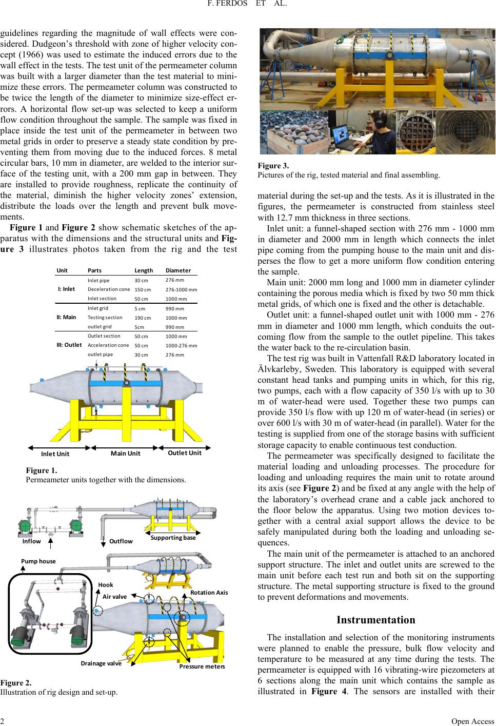 F. FERDOS ET AL. Open Access 2 guidelines regarding the magnitude of wall effects were con- sidered. Dudgeon’s threshold with zone of higher velocity con- cept (1966) was used to estimate the induced errors due to the wall effect in the tests. The test unit of the permeameter column was built with a larger diameter than the test material to mini- mize these errors. The permeameter column was constructed to be twice the length of the diameter to minimize size-effect er- rors. A horizontal flow set-up was selected to keep a uniform flow condition throughout the sample. The sample was fixed in place inside the test unit of the permeameter in between two metal grids in order to preserve a steady state condition by pre- venting them from moving due to the induced forces. 8 metal circular bars, 10 mm in diameter, are welded to the interior sur- face of the testing unit, with a 200 mm gap in between. They are installed to provide roughness, replicate the continuity of the material, diminish the higher velocity zones’ extension, distribute the loads over the length and prevent bulk move- ments. Figure 1 and Figu re 2 show schematic sketche s of the ap- paratus with the dimensions and the structural units and Fig- ure 3 illustrates photos taken from the rig and the test Figure 1. Permeameter units together with the dimensions. Figure 2. Illustration of rig design and set-up. Figure 3. Pictures of the rig, tested material and final assembling. material during the set-up and the tests. As it is illustrated in the figures, the permeameter is constructed from stainless steel with 12.7 mm thickness in three sections. Inlet unit: a funnel-shaped section with 276 mm - 1000 mm in diameter and 2000 mm in length which connects the inlet pipe coming from the pumping house to the main unit and dis- perses the flow to get a more uniform flow condition entering the sample. Main unit: 2000 mm long and 1000 mm in diameter cylinder containing the porous media which is fixed by two 50 mm thick metal grids, of which one is fixed and the other is detachable. Outlet unit: a funnel-shaped outlet unit with 1000 mm - 276 mm in diameter and 1000 mm length, which conduits the out- coming flow from the sample to the outlet pipeline. This takes the water back to the re-circulation basin. The test rig was built in Vattenfall R&D laboratory located in Älvkarleby, Sweden. This laboratory is equipped with several constant head tanks and pumping units in which, for this rig, two pumps, each with a flow capacity of 350 l/s with up to 30 m of water-head were used. Together these two pumps can provide 350 l/s flow with up 120 m of water-head (in se ries) or over 600 l/s with 30 m of water-head (in parallel). Water for the testing is supplied from one of the storage basins with sufficient storage capacity to enable continuous test conduction. The permeameter was specifically designed to facilitate the material loading and unloading processes. The procedure for loading and unloading requires the main unit to rotate around its axis (see Figure 2) and be fixed at any angle with the help of the laboratory’s overhead crane and a cable jack anchored to the floor below the apparatus. Using two motion devices to- gether with a central axial support allows the device to be safely manipulated during both the loading and unloading se- quences. The main unit of the permeameter is attached to an anchored support structure. The inlet and outlet units are screwed to the main unit before each test run and both sit on the supporting structure. The metal supporting structure is fixed to the ground to prevent deformations and movements. Instrumentat ion The installation and selection of the monitoring instruments were planned to enable the pressure, bulk flow velocity and temperature to be measured at any time during the tests. The permeameter is equipped with 16 vibrating-wire piezometers at 6 sections along the main unit which contains the sample as illustrated in Figure 4. The sensors are installed with their Inlet Unit Main Unit Outlet Unit Unit Parts Length Diameter Inlet pipe30 cm 276 mm Deceleration cone150 cm276-1000 mm Inlet section50 cm1000 mm Inlet grid5 cm990 mm Testing section190 cm1000 mm outlet grid5cm 990 mm Outlet section50 cm1000 mm Acceleration cone50 cm1000-276 mm outlet pipe30 cm276 mm II: Main I: Inlet III: Outlet Outflow Supporting base Pump house Pressure meters Drainage valve Air valve Rotation A xi s Inf low Hook 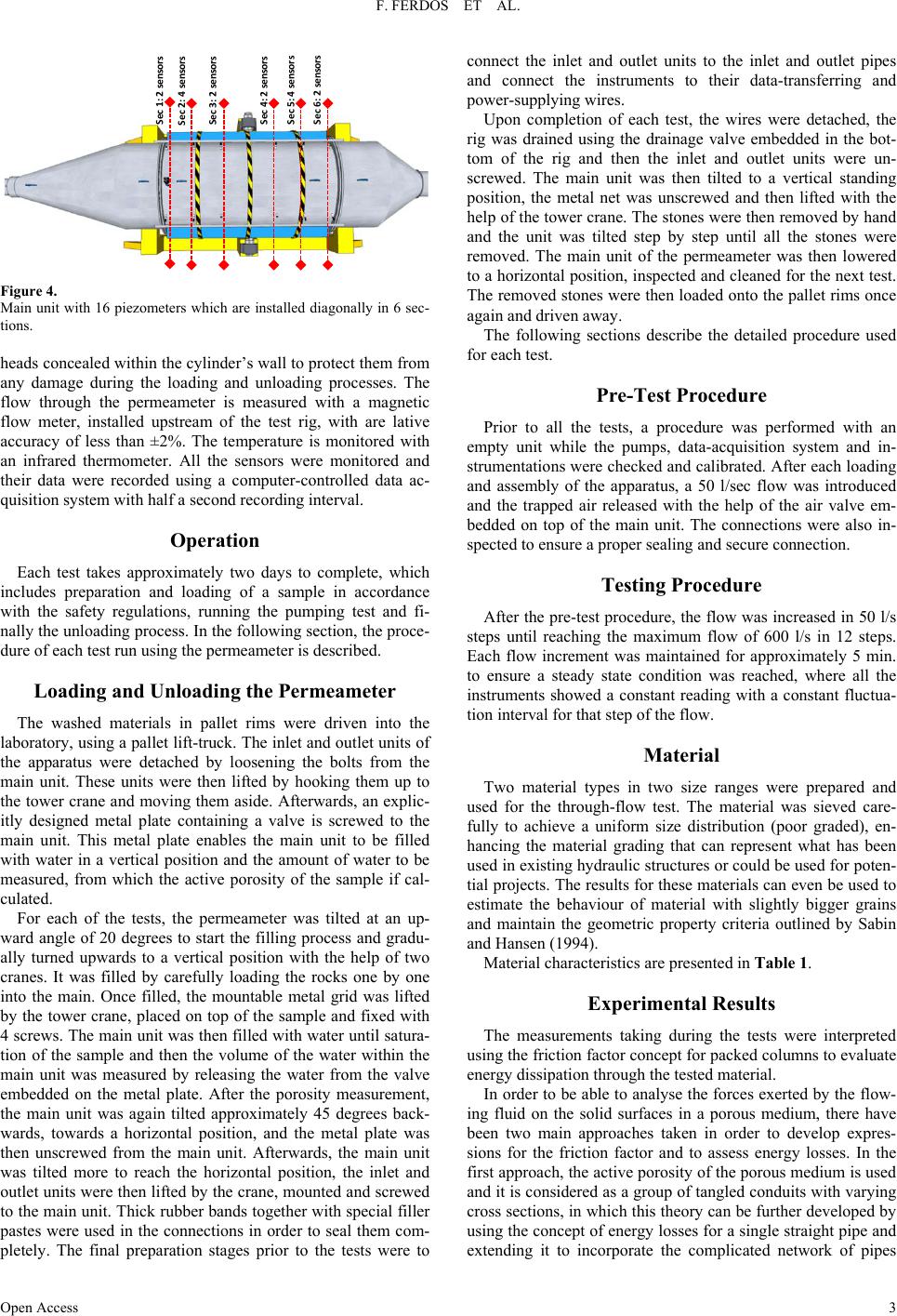 F. FERDOS ET AL. Open Access 3 Figure 4. Main unit with 16 p iezometers which are installed diagon ally in 6 sec- tions. heads concealed within the cylinder’s wall to protect them from any damage during the loading and unloading processes. The flow through the permeameter is measured with a magnetic flow meter, installed upstream of the test rig, with are lative accuracy of less than ±2%. The temperature is monitored with an infrared thermometer. All the sensors were monitored and their data were recorded using a computer-controlled data ac- quisition system with half a second recording interval. Operation Each test takes approximately two days to complete, which includes preparation and loading of a sample in accordance with the safety regulations, running the pumping test and fi- nally the unloading process. In the following section, the proce- dure of each test run using the permeameter is described. Loading and Unloading the Permeameter The washed materials in pallet rims were driven into the laboratory, using a pallet lift-truck. The inlet and outlet units of the apparatus were detached by loosening the bolts from the main unit. These units were then lifted by hooking them up to the tower crane and moving them aside. Afterwards, an explic- itly designed metal plate containing a valve is screwed to the main unit. This metal plate enables the main unit to be filled with water in a vertical position and the amount of water to be measured, from which the active porosity of the sample if cal- culated. For each of the tests, the permeameter was tilted at an up- ward angle of 20 degrees to start the filling process and gradu- ally turned upwards to a vertical position with the help of two cranes. It was filled by carefully loading the rocks one by one into the main. Once filled, the mountable metal grid was lifted by the tower crane, placed on top of the sample and fixed with 4 screws. The main unit was then filled with water until satura- tion of the sample and then the volume of the water within the main unit was measured by releasing the water from the valve embedded on the metal plate. After the porosity measurement, the main unit was again tilted approximately 45 degrees back- wards, towards a horizontal position, and the metal plate was then unscrewed from the main unit. Afterwards, the main unit was tilted more to reach the horizontal position, the inlet and outlet units were then lifted by the crane, mounted and screwed to the main unit. Thick rubber bands together with special filler pastes were used in the connections in order to seal them com- pletely. The final preparation stages prior to the tests were to connect the inlet and outlet units to the inlet and outlet pipes and connect the instruments to their data-transferring and power-supplying wires. Upon completion of each test, the wires were detached, the rig was drained using the drainage valve embedded in the bot- tom of the rig and then the inlet and outlet units were un- screwed. The main unit was then tilted to a vertical standing position, the metal net was unscrewed and then lifted with the help of the tower crane. The stones were then removed by hand and the unit was tilted step by step until all the stones were removed. The main unit of the permeameter was then lowered to a horizontal position, inspected and cleaned for the next test. The removed stones were then loaded onto the pallet rims once again and driven away. The following sections describe the detailed procedure used for each test. Pre-Test Procedure Prior to all the tests, a procedure was performed with an empty unit while the pumps, data-acquisition system and in- strumentations were checked and calibrated. After each loading and assembly of the apparatus, a 50 l/sec flow was introduced and the trapped air released with the help of the air valve em- bedded on top of the main unit. The connections were also in- spected to ensure a proper sealing and secure connection. Testing Proced ure After the pre-test procedure, the flow was increased in 50 l/s steps until reaching the maximum flow of 600 l/s in 12 steps. Each flow increment was maintained for approximately 5 min. to ensure a steady state condition was reached, where all the instruments showed a constant reading with a constant fluctua- tion interval for that step of the flow. Material Two material types in two size ranges were prepared and used for the through-flow test. The material was sieved care- fully to achieve a uniform size distribution (poor graded), en- hancing the material grading that can represent what has been used in existing hydraulic structures or could be used for poten- tial projects. The results for these materials can even be used to estimate the behaviour of material with slightly bigger grains and maintain the geometric property criteria outlined by Sabin and Hansen (1994). Material char acteristi cs are present ed in Table 1. Experimental Results The measurements taking during the tests were interpreted using the friction factor concept for packed columns to evalua te energy dissipation through the tested material. In order to be able to analyse the forces exerted by the flow- ing fluid on the solid surfaces in a porous medium, there have been two main approaches taken in order to develop expres- sions for the friction factor and to assess energy losses. In the first approach, the active porosity of the porous medium is used and it is considered as a group of tangled conduits with varying cross sections, in which this theory can be further developed by using the concept of energy losses for a single straight pipe and extending it to incorporate the complicated network of pipes Sec 1: 2 sensors Sec 2: 4 sensors Sec 3: 2 sensors Sec 4: 2 sensors Sec 5: 4 sensors Sec 6: 2 sensors 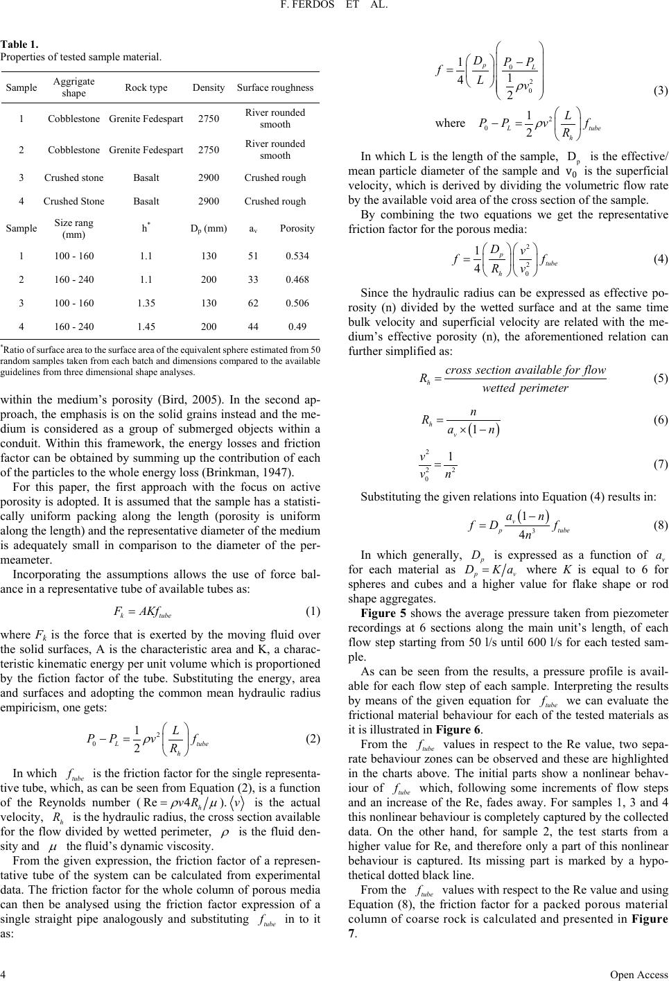 F. FERDOS ET AL. Open Access 4 Table 1. Properties of tested sample material. Sample Aggrigate shape Rock t ype Density Surface roughne s s 1 Cobblestone Grenite Fedespart 2750 River rounded smooth 2 Cobblestone Grenite Fedespart 2750 River rounded smooth 3 Crushed stone Basalt 2900 Crushed rough 4 Crushed Stone Basalt 2900 Crushed rough Sample Size rang (mm) h* Dp (mm) av Porosity 1 100 - 160 1.1 130 51 0.534 2 160 - 240 1.1 200 33 0.468 3 100 - 160 1.35 130 62 0.506 4 160 - 240 1.45 200 44 0.49 *Ratio of sur face are a to the surfa ce area of t he equivale nt sphere est imated fr om 50 random samples taken from each batch and dimensions compared to the available guidelines from three d imensional shape analyses. within the medium’s porosity (Bird, 2005). In the second ap- proach, the emphasis is on the solid grains instead and the me- dium is considered as a group of submerged objects within a conduit. Within this framework, the energy losses and friction factor can be obtained by summing up the contribution of each of the particles to the whole energy loss (Brinkman, 1947). For this paper, the first approach with the focus on active porosity is adopted. It is assumed t hat the sample has a statisti- cally uniform packing along the length (porosity is uniform along the length) and the representative diameter of the medium is adequately small in comparison to the diameter of the per- meameter. Incorporating the assumptions allows the use of force bal- ance in a representative tube of available tubes as: k tube F AKf= (1) where Fk is the force that is exerted by the moving fluid over the solid surfaces, A is the characteristic area and K, a charac- teristic kinematic energy per unit volume which is proportioned by the fiction factor of the tube. Substituting the energy, area and surfaces and adopting the common mean hydraulic radius empiricism , one gets: 2 0 1 2 L tube h L PP vf R ρ −= (2) In which tube f is the friction factor for the single representa- tive tube, which, as can be seen from Equation (2), is a function of the Reynolds number ( Re 4 h vR ρµ = ). v is the actual velocity, h R is the hydraulic radius, the cross section available for the flow divided by wetted perimeter, ρ is the fluid den- sity and µ the fluid’s dynamic vi sc osity . From the given expression, the friction factor of a represen- tative tube of the system can be calculated from experimental data. The friction factor for the whole column of porous media can then be analysed using the friction factor expression of a single straight pipe analogously and substituting tube f in to it as: 0 2 0 2 0 11 42 1 where 2 pL L tube h DPP fLv L PP vf R ρ ρ − = −= (3) In which L is the length of the sample, p D is the effective/ mean particle diameter of the sample and v0 is the superficial velocity, which is derived by dividing the volumetric flow rate by the available void area of the cross section of the sample. By combining the two equations we get the representative friction factor for the porous media: 2 2 0 1 4 p tube h Dv ff Rv = (4) Since the hydraulic radius can be expressed as effective po- rosity (n) divided by the wetted surface and at the same time bulk velocity and superficial velocity are related with the me- dium’s effective porosity (n), the aforementioned relation can further simplified as: h cross section available forflow Rwetted perimeter = (5) ( ) 1 h v n Ran =×− (6) 2 22 0 1v vn = (7) Substituting the given relations into Equation (4) results in: ( ) 3 1 4 v p tube an fD f n − = (8) In which generally, p D is expressed as a function of v a for each material as pv D Ka= where K is equal to 6 for spheres and cubes and a higher value for flake shape or rod shape aggregates. Figure 5 shows the average pressure taken from piezometer recordings at 6 sections along the main unit’s length, of each flow step starting from 50 l/s until 600 l/s for each tested sam- ple. As can be seen from the results, a pressure profile is avail- able for each flow step of each sample. Interpreting the results by means of the given equation for tube f we can evaluate the frictional material behaviour for each of the tested materials as it is illustrated in Figure 6. From the tube f values in respect to the Re value, two sepa- rate behaviour zones can be observed and these are highlighted in the charts above. The initial parts show a nonlinear behav- iour of tube f which, following some increments of flow steps and an increase of the Re, fades away. For samples 1, 3 and 4 this nonlinear behaviour is completely captured by the collected data. On the other hand, for sample 2, the test starts from a higher value for Re, and therefore only a part of this nonlinear behaviour is captured. Its missing part is marked by a hypo- thetical dotted black line. From the tube f values with respect to the Re value and using Equation (8), the friction factor for a packed porous material column of coar se rock is calculated and presented in Figure 7. 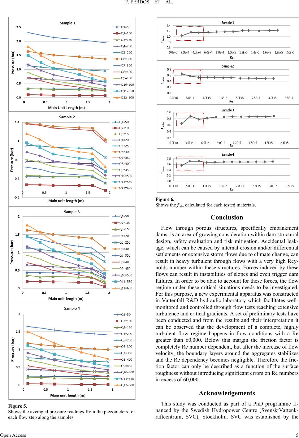 F. FERDOS ET AL. Open Access 5 Figure 5. Shows the averaged p ressure readings fro m the piezometers for each flow step along the samples. Figure 6. Shows the ftube calculated for each tested materials. Conclusion Flow through porous structures, specifically embankment dams, is an area of growing consideration within dam structural design, safety evaluation and risk mitigation. Accidental leak- age, which can be caused by internal erosion and/or differential settlements or extensive storm flows due to climate change, can result in heavy turbulent through flows with a very high Rey- nolds number within these structures. Forces induced by these flows can result in instabilities of slopes and even trigger dam failures. In order to be able to account for these forces, the flow regime under these critical situations needs to be investigated. For this purpose, a new experimental apparatus was constructed in Vattenfall R&D hydraulic laboratory which facilitates well- monitored and controlled through flow tests reaching extensive turbulence and critical gradients. A set of preliminary tests have been conducted and from the results and their interpretation it can be observed that the development of a complete, highly turbulent flow regime happens in flow conditions with a Re greater than 60,000. Below this margin the friction factor is completely Re number dependent, but after the increase of flow velocity, the boundary layers around the aggregates stabilizes and the Re dependency becomes negligible. Therefore the fric- tion factor can only be described as a function of the surface roughness without introducing significant errors on Re numbers in excess of 60,000. Acknowledgements This study was conducted as part of a PhD programme fi- nanced by the Swedish Hydropower Centre (SvensktVattenk- raftcentrum, SVC), Stockholm. SVC was established by the 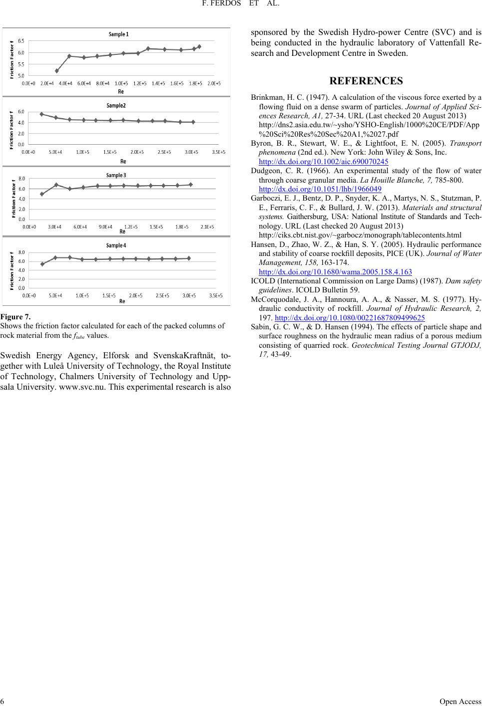 F. FERDOS ET AL. Open Access 6 Figure 7. Shows the friction factor calculated for each of the packed columns of rock material from the ftube values. Swedish Energy Agency, Elforsk and SvenskaKraftnät, to- gether with Luleå University of Technology, the Royal Institute of Technology, Chalmers University of Technology and Upp- sala University . www.svc.nu. This experimental research is also sponsored by the Swedish Hydro-power Centre (SVC) and is being conducted in the hydraulic laboratory of Vattenfall Re- search and Development Centre in Sweden. REFERENCES Brinkman, H. C. ( 194 7). A calcu latio n of the visco us force exe rted by a flowing fluid on a dense swarm of particles. Journal of Applied Sci- ences Research, A1, 27-34. URL (Last checke d 20 August 2013) http://dns2.asia.edu.tw/~ysho/YSHO-English/1000%20CE/PDF/App %20Sci%20Res%20Sec%20A1,%2027.pdf Byron, B. R., Stewart, W. E., & Lightfoot, E. N. (2005). Transport phenomena (2nd ed.). New York: John Wiley & Sons, Inc. http://dx.doi.org/10.1002/aic.690070245 Dudgeon, C. R. (1966). An experimental study of the flow of water through coarse granular media. La Houille Blanche, 7, 785-800. http://dx.doi.org/10.1051/lhb/1966049 Garboczi, E. J., Be n tz, D. P., Snyder, K. A., Martys, N. S., Stutzman, P. E., Ferraris, C. F., & Bullard, J. W. (2013). Materials and structural systems. Gaithersburg, USA: National Institute of Standards and Tech- nology. URL (L ast checked 20 August 2013) http://ciks.cbt.nist.gov/~garbocz/monograph/tablecontents.html Hansen, D., Zhao, W . Z., & Han, S. Y. (2005). Hydraulic p erformance and stability of coarse rockfill deposits, PICE (UK). Journal of Water Management, 158, 163-174. http://dx.doi.org/10.1680/wama.2005.158.4.163 ICOLD (International Commission o n Large Da ms) (1987). Dam safety guidelines. ICOLD Bulletin 59. McCorquodale, J. A., Hannoura, A. A., & Nasser, M. S. (1977). Hy- draulic conductivity of rockfill. Journal of Hydraulic Research, 2, 197. http://dx.doi.org/10.1080/00221687809499625 Sabin, G. C. W., & D. Han sen (1994). The effects of p article shape and surface roughness on the hydraulic mean radius of a porous medium consisting of quarried rock. Geotechnical Testing Journal GTJODJ, 17, 43-49. |