

Paper Menu >>
Journal Menu >>
 Journal of Power and Energy Engineering, 2013, 1, 45-50 http://dx.doi.org/10.4236/jpee.2013.17008 Published Online December 2013 (http://www.scirp.org/journal/jpee) Copyright © 2013 SciRes. JPEE 45 Cold-State Investiga ti on on a Flame Holder Yiqing Du School of Energy and Power Engineering, Huazhong University of Science and Technology, Wuhan, China. Email: [email protected] Received October 2013 ABSTRACT Slitty bluff body is w idely used as a high-perfor mance flame holder in power industry. To understand the flame stability mechanism, the evolution of the n ear wake over a slitty bluff body in cold state was numerically investigated using the renormalization group (RNG) k-ε model at Reynolds number of 470,000. The coherent structure of the near wake was identified by the vortex shedding simulation. To explain the vortex shedding, a mechanism that single vortex of large size suddenly immerses two shear layers was proposed. To quantitatively compare the near wakes at different gap ratio, a vortex shedding character dimension was first proposed. This character dimension has positive correlation with flame stability. Particle-image velocimetry (PIV) measurements in a close wind tunnel were also carried out to confirm the observation from the numerical study. The evidence shows that the numerical results are of good agreement with the cold-state experiments. Keywords: Flame Holder; Bluff Body; Flame Stability; Coherent Structure; Vortex Shedding 1. Introduction Bluff body flame holders are widely used to make flames stable in industry, especially for combustors with high velocity flows. Many research conducted during the past five decades indicates that the wake flow structure be- hind the bluff body is directly related to the flame-hold- ing performance. The wake contains the complexities of separation and recirculation, mass and momentum trans- port across the shear layers, and vortex shedding dynam- ics. However, the study of the flow structure has not been thoroughly explored. Yang and Tsai (1993) have expe- rimentally investigated the effects of the width of gap on the recirculation zone and the drag in the near wake of a slitty bluff body in a confined tunnel at Re = 120,000 [1]. According to their experimental evidence, an asymmetric wake structure is developed behind the symmetric slit (G/D = 0.2 and 0.4). Compared with traditional bluff body the slitty bluff body has better flame holding ability and less pressure loss because the gap flow induces great reverse flow and greater back pressure in the near wake. Their investigations also indicate that the gap flow pro- vokes more extensive transport across the shear layers and reduces both the turbulent intensity and the Reynolds shear stress of the wake, but no more data with different gap ratios and detailed analysis on the wake structure has been reported. The understanding of flame holding mechanism of a slitty bluff body is incomplete without an understanding of the coherent structure in its near wake. Flow characte- ristics and vortical motion within the near wake are the major interest of the present work. The simulation on flows of engineering and industr ial interest, char acterized by high Reynolds numbers and complex geometry in con- fined tunnel, generally requires proper turbulence mod- eling. The analyses on different models, e.g. the standard k-ε, the RNG k-ε and the large eddy simulation (LES), were provided. The flow structure behind the slitty bluff body was investigated nu merically by using the RNG k-ε. Experimental results using PIV measurements in a close wind tunnel were also provided to confirm the observa- tion from the related numerical cold-state study. 2. Numerical Simulation 2.1. Calculation Model and Condition Figure 1 shows the geometrical parameters and the co- ordinate system used for the 2D case considered. The slitty bluff body of triangle cross-section with side di- mension D and gap dimension G, is immersed in a uni- form velocity stream U. The resulting characteristic Rey- nolds number (Re = ULi/γ) is fixed to 470,000. The di- mensions of the computational domain are Li, Lx, Ly (250 mm, 450 mm, 200 mm). The slitty bluff body is in the middle of a confined tunnel with its axis normal to the inlet side. The flame holder problems involve very complicated flow behaviors that cannot be accurately simulated using improper computational methods. In addition, the physi- 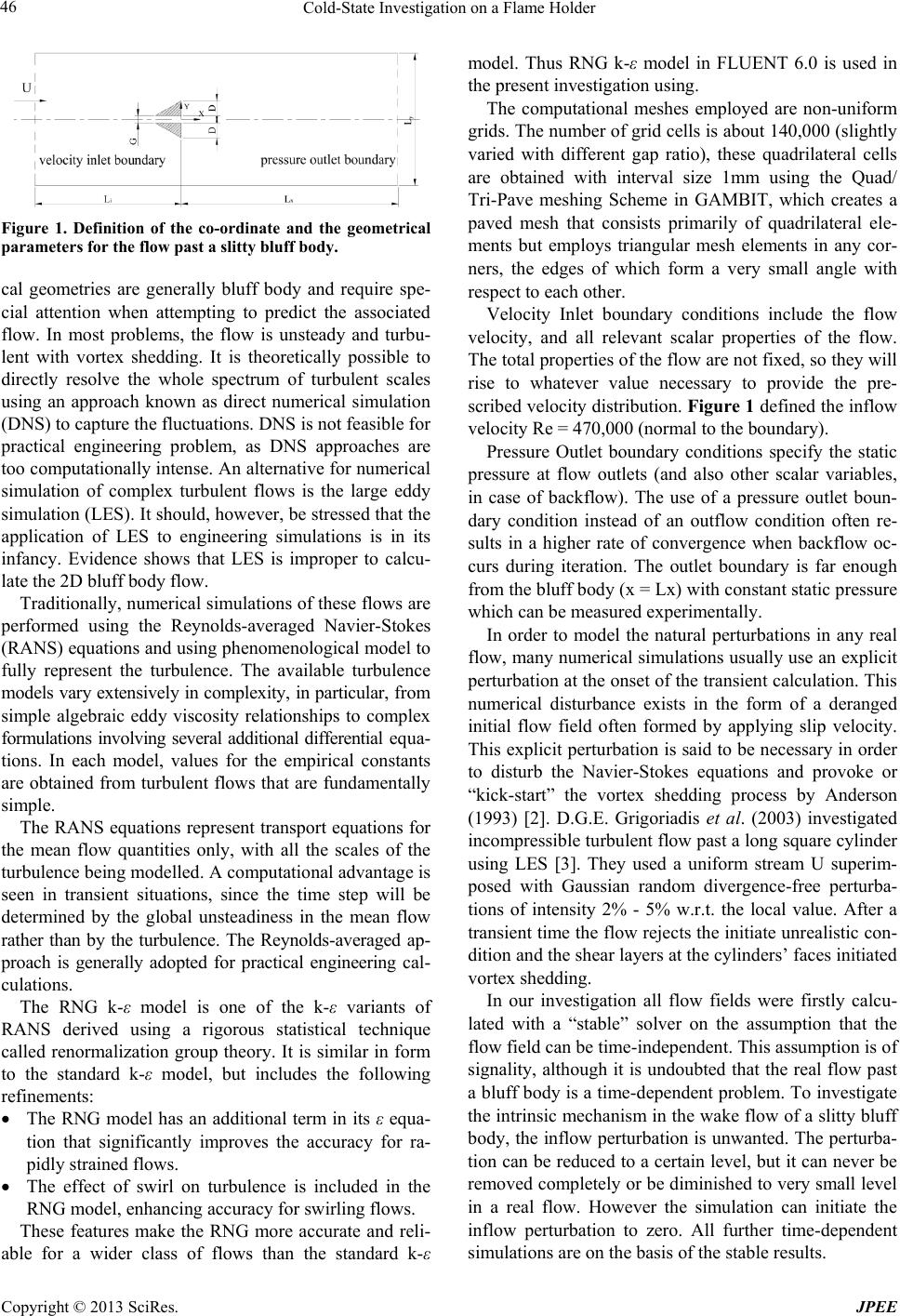 Cold-State Investigation on a Flame Holder Copyright © 2013 SciRes. JPEE 46 Figure 1. Definition of the co-ordinate and the geometrical parameters for the flow past a slitty bluff body. cal geometries are generally bluff body and require spe- cial attention when attempting to predict the associated flow. In most problems, the flow is unsteady and turbu- lent with vortex shedding. It is theoretically possible to directly resolve the whole spectrum of turbulent scales using an approach known as direct numerical simulation (DNS) to capture the fluctuations. DNS is not feasible for practical engineering problem, as DNS approaches are too computationally inten se. An alternative f or numerical simulation of complex turbulent flows is the large eddy simulation (LES). It should, however, be stressed that the application of LES to engineering simulations is in its infancy. Evidence shows that LES is improper to calcu- late the 2D bluff body flow. Traditionally, numerical si mulations of these flows are performed using the Reynolds-averaged Navier-Stokes (RANS) equations and using phenomenological model to fully represent the turbulence. The available turbulence models vary extensively in complexity, in particular, from simple algebraic eddy viscosity relationships to complex formulations involving several additional differential equa- tions. In each model, values for the empirical constants are obtained from turbulent flows that are fundamentally simple. The RANS equations represent transport equations for the mean flow quantities only, with all the scales of the turbulence being modelled. A computational advantage is seen in transient situations, since the time step will be determined by the global unsteadiness in the mean flow rather than by the turbulence. The Reynolds-averaged ap- proach is generally adopted for practical engineering cal- culations. The RNG k-ε model is one of the k-ε variants of RANS derived using a rigorous statistical technique called renormalization group theory. It is similar in form to the standard k-ε model, but includes the following refinements: • The RNG model has an additional term in its ε equa- tion that significantly improves the accuracy for ra- pidly strained flows. • The effect of swirl on turbulence is included in the RNG model, enhancing accuracy for swirling flows. These features make the RNG more accurate and reli- able for a wider class of flows than the standard k-ε model. Thus RNG k-ε model in FLUENT 6.0 is used in the present investigation using. The computational meshes employed are non-uniform grids. The number of grid cells is about 140,000 (slightly varied with different gap ratio), these quadrilateral cells are obtained with interval size 1mm using the Quad/ Tri-Pave meshing Scheme in GAMBIT, which creates a paved mesh that consists primarily of quadrilateral ele- ments but employs triangular mesh elements in any cor- ners, the edges of which form a very small angle with respect to each other. Velocity Inlet boundary conditions include the flow velocity, and all relevant scalar properties of the flow. The total properties of the f low are not fixed, so they will rise to whatever value necessary to provide the pre- scribed velocity dis tribution. Figure 1 defined the inf low velocity Re = 470,000 (nor mal to the boundary). Pressure Outlet boundary conditions specify the static pressure at flow outlets (and also other scalar variables, in case of backflow). The use of a pressure outlet boun- dary condition instead of an outflow condition often re- sults in a higher rate of convergence when backflow oc- curs during iteration. The outlet boundary is far enough from the bluff body (x = Lx) with constant static pressure which can be measured experimentally. In order to model the natural perturbations in any real flow, many numerical simulation s usually use an explicit perturbation at the onset of the trans ient calculation. This numerical disturbance exists in the form of a deranged initial flow field often formed by applying slip velocity. This explicit perturbation is said to be necessary in order to disturb the Navier-Stokes equations and provoke or “kick-start” the vortex shedding process by Anderson (1993) [2]. D.G.E. Grigoriadis et al. (2003) investigated incompressible turbulent flow past a long square cylinder using LES [3]. They used a uniform stream U superim- posed with Gaussian random divergence-free perturba- tions of intensity 2% - 5% w.r.t. the local value. After a transient time the flow rejects the initiate unrealistic co n- dition and the shear layers at the cylinders’ faces initiated vortex shedding. In our investigation all flow fields were firstly calcu- lated with a “stable” solver on the assumption that the flow field can be time-independent. This assumption is of signality, although it is undoubted that the real flow past a bluff body is a ti me-dependent problem. To investigate the intrinsic mechanism in the w ake flow of a slitty bluff body, the inflow perturbation is unwanted. The perturba- tion can be reduced to a certain level, but it can never be removed completely or be diminished to very small level in a real flow. However the simulation can initiate the inflow perturbation to zero. All further time-dependent simulations are on the basis of the stable results. 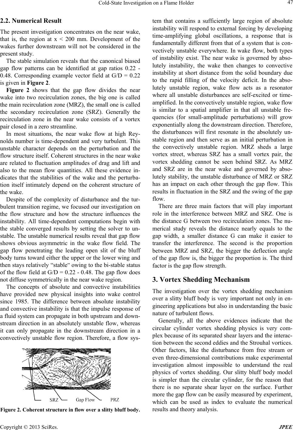 Cold-State Investigation on a Flame Holder Copyright © 2013 SciRes. JPEE 47 2.2. Numerical Result The present investigation concentrates on the near wake, that is, the region at x < 200 mm. Development of the wakes further downstream will not be considered in the present study. The stable simulation reveals tha t the canonical biased gap flow patterns can be identified at gap ratios 0.22 - 0.48. Corresponding example vector field at G/D = 0.22 is given in Figure 2. Figure 2 shows that the gap flow divides the near wake into two recirculation zones, the big one is called the main rec ircu lation zone ( MRZ), the sma ll one is called the secondary recirculation zone (SRZ). Generally the recirculation zone in the near wake consists of a vortex pair closed in a zero streamline. In most situations, the near wake flow at high Rey- nolds nu mber is time-dependent and very turbulent. This unstable character depends on the perturbation and the flow structure itself. Coherent structures in the near wake are related to fluctuation amplitudes of drag and lift and also to the mean flow quantities. All these evidence in- dicates that the stabilities of the wake and the perturba- tion itself intimately depend on the coherent structure of the wake. Despite of the complexity of disturbance and the tur- bulent transition regime, we f ocused our investigation on the flow structure and how the structure influences the instability. All time-dependent computations begin with the stable converged results by setting the solver to un- stable. The unstab le numerical resu lts reveal that gap flow shows obvious asymmetric in the wake flow field. The gap flow penetrating the leading open slit of the bluff body turns toward either the upper or the lower wing and then stays relativ ely “stable” owing to the bi-stable status of th e flow field at G/D = 0.22 - 0.48. The gap flow does not diffuse symmetrically in the near wake region. The concepts of absolute and convective instabilities have provided new physical insights into wake control since 1985. The difference between absolute instability and convective instability is that th e impulse response of a fluid system can propagate in both upstream and down- stream direction in an absolutely unstable flow, whereas it can only propagate in the downstream direction in a convectively unstable flow region. Therefore, a flow sys- Figure 2. Coherent structure in flow over a slitty bluff body. tem that contains a sufficiently large region of absolute instability will respond to externa l forcing by developing time-amplifying global oscillations, a response that is fundamentally different from that of a system that is co n- vectively unstable everywhere. In wake flow, both types of instability exist. The near wake is governed by abso- lutely instability, the wake then changes to convective instability at short distance from the solid boundary due to the rapid filling of the velocity deficit. In the abso- lutely unstable region, wake flow acts as a resonator where all unstable disturbances are self-excited or time- amplified. In the convectively unstable region, wake flow is similar to a spatial amplifier in that all unstable fre- quencies (for small-amplitude perturbations) will grow exponentially along the downstream direction. Therefore, the disturbances will first resonate in the absolutely un- stable region and then serve as an initial perturbation in the convectively unstable region. MRZ sheds a large vortex street, whereas SRZ has a small vortex pair, the vortex shedding cannot be seen behind SRZ. As MRZ and SRZ are in the near wake and governed by abso- lutely stability, the unstable disturbance of MRZ or SRZ has an impact on each other through the gap flow. This results in fluctuation in the SRZ and the swing of the gap flow. There are three main factors that will play important role in the interference between MRZ and SRZ. One is the distance G between two recirculation zones. The nu- merical study reveals the distance nearly equals to the gap width, a smaller distance G can make it easier to transfer the interference. The second is the proportion between MRZ and SRZ, the bigger the deflection angle of the gap flow is, the bigger the proportion is. The third factor is the gap flow strength. 3. Vortex Shedding Mechanism The investigation over the vortex shedding mechanism over a slitty bluff body is very important not only in en- gineering applications but also in understanding the basic nature of turbulent flows. Generally, all the above evidences indicate that the circular cylinder vortex shedding physics is very com- plex because of its separated shear layers and the interac- tion between the second eddies and the Strouhal vortices. Other factors, like the disturbance from free stream or even three-dimensional contributions make experimental investigation almost impossible to understand the real physics of vortex shedding. Our slitty bluff body model is simpler than the circular cylinder, for the reason that there is no separate shear layer on the surface. Further more the gap flow can be easily measured by experiment, which can be used as index to evaluate the numerical results and theory analysis. 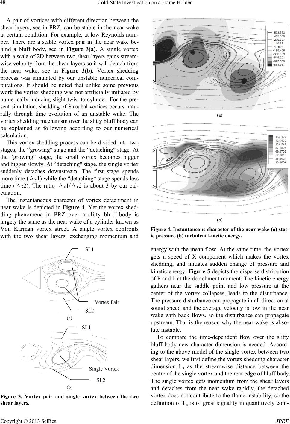 Cold-State Investigation on a Flame Holder Copyright © 2013 SciRes. JPEE 48 A pair of vortices with different direction between the shear layers, see in PRZ, can be stable in the near wake at certain condition. For example, at low Reynolds num- ber. There are a stable vortex pair in the near wake be- hind a bluff body, see in Figure 3(a). A single vortex with a scale of 2D between two shear layers gains stream- wise velocity from the shear layers so it will detach from the near wake, see in Figure 3(b). Vortex shedding process was simulated by our unstable numerical com- putations. It should be noted that unlike some previous work the vortex shedding was not artificiall y initiated by numerically inducing slight twist to cylinder. For the pre- sent simulation, shedding of Strouhal vortices occurs natu- rally through time evolution of an unstable wake. The vortex shedding mechanism over the slitty bluff body can be explained as following according to our numerical calculation. This vortex shedding process can be divided into two stages, the “growing” stage and the “detaching” stage. At the “growing” stage, the small vortex becomes bigger and bigger slowly. At “detaching” stage, the single vortex suddenly detaches downstream. The first stage spends mor e time (Δτ1) while the “detaching” stage spends less time (Δτ2). The ratio Δτ1/Δτ2 is about 3 by our cal- culation. The instantaneous character of vortex detachment in near wake is depicted in Figure 4. Yet the vortex shed- ding phenomena in PRZ over a slitty bluff body is largely the same as the near wake of a cylinder known as Von Karman vortex street. A single vortex confronts with the two shear layers, exchanging momentum and (a) (b) Figure 3. Vortex pair and single vortex between the two shear layers. (a) (b) Figure 4. Instantaneous character of the near wake (a) stat- ic pressure (b) tur bulent kineti c energy. energy with the mean flow. At the same time, the vortex gets a speed of X component which makes the vortex shedding, and initiates sudden change of pressure and kinetic energy. Figure 5 depicts the disperse distribution of P and k at the detachment moment. The kinetic energy gathers near the saddle point and low pressure at the center of the vortex collapses, leads to the disturbance. The pressure disturbance can propagate in all direction at sound speed and the average velocity is low in the near wake with back flows, so the disturbance can propagate upstream. That is the reason why the near wake is abso- lute instable. To compare the time-dependent flow over the slitty bluff body new character dimension is needed. Accord- ing to the above model of the single vortex between two shear layers, we first define the vortex shedding character dimension Ls as the streamwise distance between the centre of the single vortex and the rear edge of bluff body. The single vortex gets momentum from the shear layers and detaches from the near wake rapidly, the detached vortex does not contribute to the flame instability, so the definition of Ls is of great signality in quantitively com- 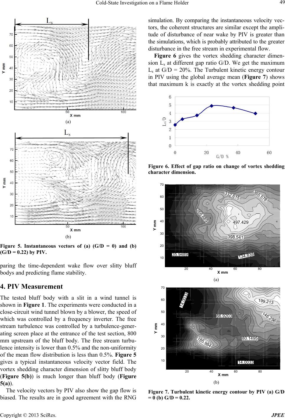 Cold-State Investigation on a Flame Holder Copyright © 2013 SciRes. JPEE 49 (a) (b) Figure 5. Instantaneous vectors of (a) (G/D = 0) and (b) (G/D = 0.22) by PIV. paring the time-dependent wake flow over slitty bluff bodys and predicting flame stability. 4. PIV Measurement The tested bluff body with a slit in a wind tunnel is shown in Figure 1. The experiments were conducted in a close-circuit wind tunnel blown by a blower, the speed of which was controlled by a frequency inverter. The free stream turbulence was controlled by a turbulence-gener- ating screen place at the entrance of the test section, 800 mm upstream of the bluff body. The free stream turbu- lence intensity is lower than 0.5% and the non-uniformity of the mean flow distribution is less than 0.5%. Figur e 5 gives a typical instantaneous velocity vector field. The vortex shedding character dimension of slitty bluff body (Figure 5(b)) is much longer than bluff body (Figure 5(a)). The velocity vectors by PIV also show the gap flow is biased. The results are in good agreement with the RNG simulation. By comparing the instantaneous velocity vec- tors, the coherent structures are similar except the ampli- tude of disturbance of near wake by PIV is greater than the simulations, which is probably attributed to the greater disturbance in the free stream in experimental flow. Figure 6 gives the vortex shedding character dimen- sion Ls at different gap ratio G/D. We get the maximum Ls at G/D = 20%. The Turbulent kinetic energy contour in PIV using the global average mean (Figure 7) shows that maximum k is exactly at the vortex shedding point Figure 6. Effect of gap ratio on change of vortex shedding character dimension. (a) (b) Figure 7. Turbulent kinetic energy contour by PIV (a) G/D = 0 (b) G/D = 0.22. 497.429 398.541 332.615 266.689 365.578 134.838 35.9489 X mm Y mm 20 40 60 80 10 20 30 40 50 60 70 199.213 146.296 66.9203 185.984 80.1495 14.0033 14.0033 X mm Y mm 20 40 60 80 10 20 30 40 50 60 70 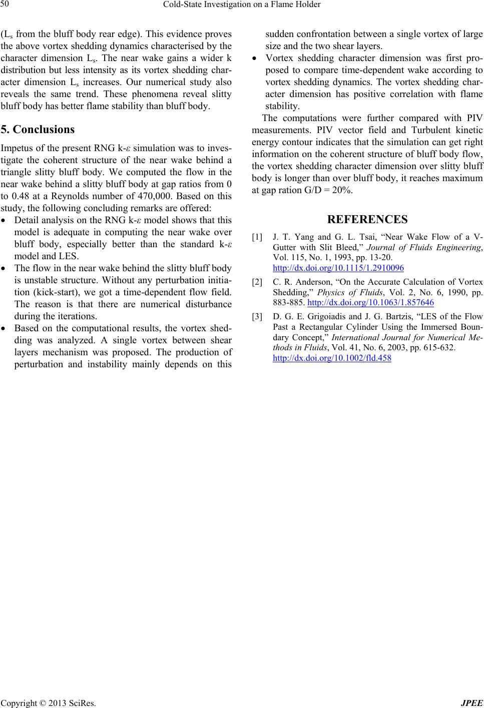 Cold-State Investigation on a Flame Holder Copyright © 2013 SciRes. JPEE 50 (Ls from the bluff body rear edge). This evidence proves the above vortex shedding dynamics characterised by the character dimension Ls. The near wake gains a wider k distribution but less intensity as its vortex shedding char- acter dimension Ls increases. Our numerical study also reveals the same trend. These phenomena reveal slitty bluff body has better flame stability than bluff body. 5. Conclusions Impetus of the present RNG k-ε simulation was to inves- tigate the coherent structure of the near wake behind a triangle slitty bluff body. We computed the flow in the near wake behind a slitty bluff body at gap ratios from 0 to 0.48 at a Reynolds number of 470,000. Based on this study, the following concluding remarks are offered: • Detail analysis on the RNG k-ε model shows that this model is adequate in computing the near wake over bluff body, especially better than the standard k-ε model and LES. • The flow in the near wake behind the slitty bluff body is unstable structure. Without any perturbation initia- tion (kick-start), we got a time-dependent flow field. The reason is that there are numerical disturbance during the iterations. • Based on the computational results, the vortex shed- ding was analyzed. A single vortex between shear layers mechanism was proposed. The production of perturbation and instability mainly depends on this sudden confrontation between a single vortex of large size and the two shear layers. • Vortex shedding character dimension was first pro- posed to compare time-dependent wake according to vortex shedding dynamics. The vortex shedding char- acter dimension has positive correlation with flame stability. The computations were further compared with PIV measurements. PIV vector field and Turbulent kinetic energy contour indicates that the simulation can get right information on th e coherent structure of bluff body flow, the vortex shedding character dimension over slitty bluff body is longer than over bluff body, it reaches maximum at gap ration G/D = 20%. REFERENCES [1] J. T. Yang and G. L. Tsai, “Near Wake Flow of a V- Gutter with Slit Bleed,” Journal of Fluids Engineering, Vol. 115, No. 1, 1993, pp. 13-20. http://dx.doi.org/10.1115/1.2910096 [2] C. R. Anderson, “On the Accurate Calculation of Vortex Shedding,” Physics of Fluids, Vol. 2, No. 6, 1990, pp. 883-885. http://dx.doi.org/10.1063/1.857646 [3] D. G. E. Grigoiadis and J. G. Bartzis, “LES of the Flow Past a Rectangular Cylinder Using the Immersed Boun- dary Concept,” International Journal for Numerical Me- thods in Fluids, Vol. 41, No. 6, 2003, pp. 615-632. http://dx.doi.org/10.1002/fld.458 |