

Paper Menu >>
Journal Menu >>
 Journal of Power and Energy Engineering, 2013, 1, 40-44 http://dx.doi.org/10.4236/jpee.2013.17007 Published Online December 2013 (http://www.scirp.org/journal/jpee) Copyright © 2013 SciRes. JPEE Study of Seals on Long Stroke and Reciprocating Motion Condition Zhaoxia Wang, Yujie Zhi, Chengyong Hu, Jinlu Xi, Jing Hu, Jie An China Petroleum Engineering Co., Ltd., Beijing, China. Email: [email protected] Received October 2013 ABSTRACT The equipment has a high and strict requirement of dynamic seals, especially working with Long stroke reciprocating motion under a sandy condition and with a great deal of gas. The seal form of power cylinder on the underground part of hydrau lic pow er rod less type oil extraction equipment is studied. We design three seal structures, do the performance testing and the life testing w ith related equipment. It turn ed out that the seal fo rm that combines gap seal with sa nd pr e- vention te chniques has hig h pe rform ance, longer life. The power cylinder works stably and reliably. Keywords: Dynamic Seals; Long Stroke; Reciprocating Motion; Gap Seal; Composite Seal 1. Introduction Dynamic seal is an important part of the machinery, it plays an important role on security, reliability and equip- ment life and operation reliability [1]. Dynamic seal also directly affect the economy of ener- gy and material. According to the survey, friction bring a very big damage on the surface of sealing, for example, in centrifugal impeller seal consumed power take up more than 20% of the total shaft power, for example [2]. Dynamic seal has a high and strict requirement for the power cylinder of oil extraction equipment which works with long stroke reciprocating motion under a sandy condition and with a great deal of gas. The cylinder of hydraulic power rodless type oil extraction equipment works in the liquid, which may contain oil, water, gas and sand, the axial movement of the dynamic seal is very difficult, the aggravation of abrasion will cause serious loss. The working stroke of hydraulic power rodless type oil extraction equipment is 3 m - 5 m, much longer than conventional hydraulic equipment, so the life of dynamic seal have a great influence on the life of the whole sys- tem. The dynamic seal problem is a bottleneck problem. We designed three combined seal forms, such as soft seal, piston seal ring and gap seal, aiming at a better seal- ing of power cylinder underground, and studied the life test technology. 2. Dynamic Sealing Structure Design In many important machines, usually we combined many sealing forms for a reliable sealing effect. [3] We do many researches and analysis of soft seal, piston seal ring and gap seal on the basis of conventional sealing forms, we also design many seal forms to find a combined dy- namic sealing form suits for hydraulic power rodless type oil extraction equipment. 2.1. Soft Seal When soft seal work is under low pre ssure condition, it is sealed by elastic of the seal ring; when under high pres- sure condition, it is sealed by the elastic and the pressure of the fluid. The higher the pressure, the more reliable of the seal, the less of the leakage, even no leakage. The section of the seal ring has 3 forms: Y-shape, V-shape, and O-shape. But it needs fluid to be very clean, because solid impurities can lead to a quicker damage to the seal, and result in the failure of the seal for excessive wear. We take the conventional soft seal form and better combined sealing material in our system. We design sand control structure with a soft seal, the structure of com- bined seal shown in Figure 1. 2.2. Unnotched Piston Seal Ring Designed an unnotched piston seal ring specific for the request and feature of combined seal structure, as shown in Figure 2. Piston ring is made by Tungsten copper chromium, CrMoCu, vanadium and titanium alloy, etc. and its surface is hardened (higher than HRC60). Piston ring has wear-resisting, high temperature resistance, good bending strength , strong sealing, etc. The piston seal r ing structure combined with sand control is shown in Figure 2. 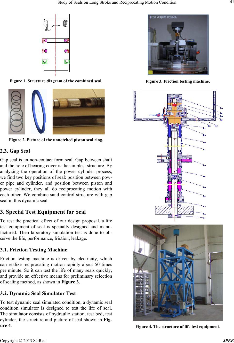 Study of Seals on Long Stroke and Reciprocating Motion Condition Copyright © 2013 SciRes. JPEE 41 Figure 1. Structure diagram of the combined seal. Figure 2. Picture of the unnotched piston seal ri ng. 2.3. Gap Seal Gap seal is an non-contact form seal. Gap between shaft and the hole of bearing cover is the simplest stru ctur e . By analyzing the operation of the power cylinder process, we find two key positions of seal: position between pow- er pipe and cylinder, and position between piston and power cylinder, they all do reciprocating motion with each other. We combine sand control structure with gap seal in this dynamic seal. 3. Special Test Equipment for Seal To test the practical effect of our design proposal, a life test equipment of seal is specially designed and manu- factured. Then laboratory simulation test is done to ob- serve the life, performance, friction, leakage. 3.1. Friction Testing Machine Friction testing machine is driven by electricity, which can realize reciprocating motion rapidly about 50 times per minute. So it can test the life of many seals quickly, and provide an effective means for preliminary selection of sealing method, as shown in Figure 3. 3.2. Dynamic Seal Simulator Test To test dynamic seal simulated condition, a dynamic seal condition simulator is designed to test the life of seal. The simulator consists of hydraulic station, test bed, test cylinder, the structure and picture of seal shown in Fig- ure 4. Figure 3. Friction testing machine. Figure 4. The structure of life test equipment. 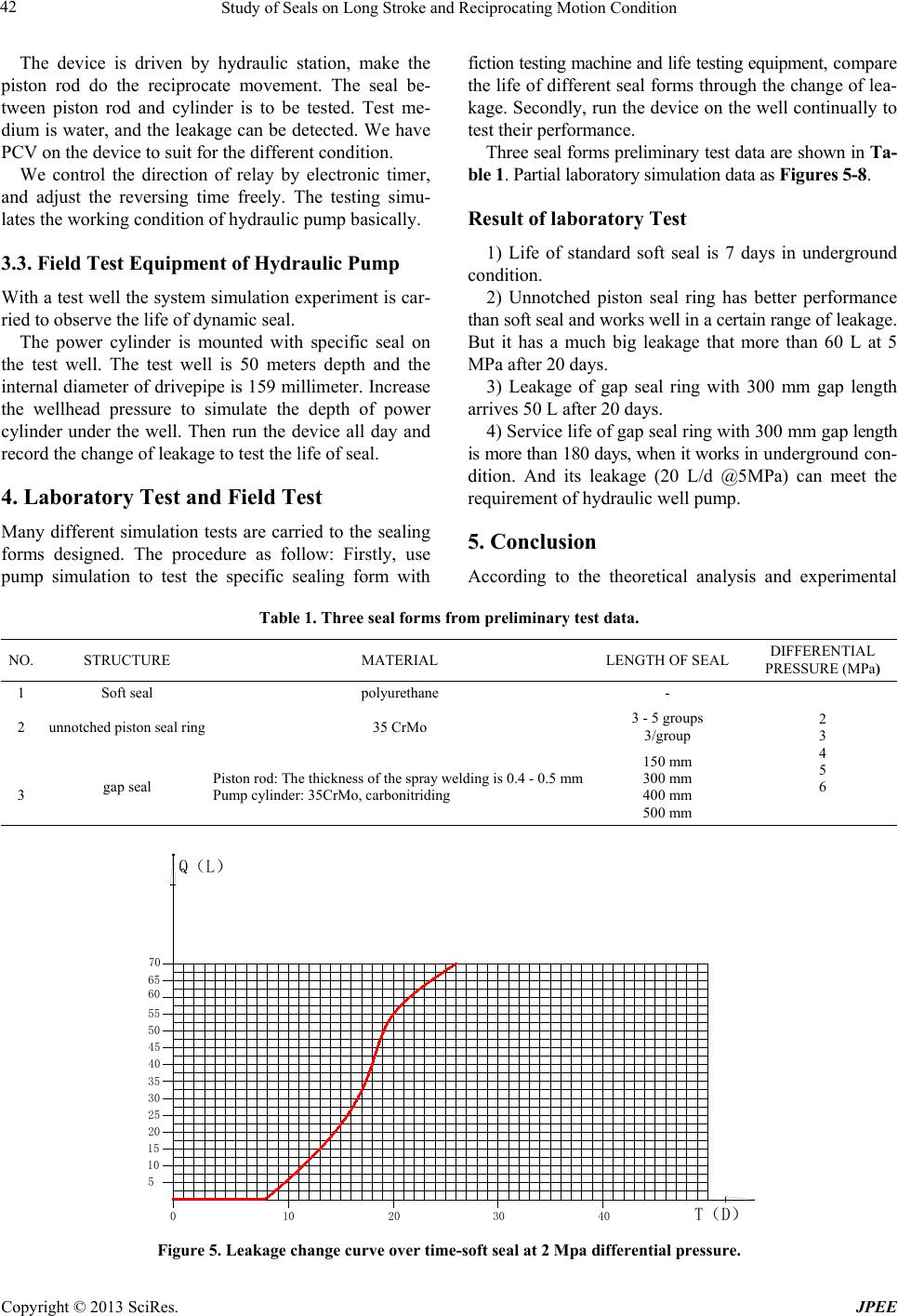 Study of Seals on Long Stroke and Reciprocating Motion Condition Copyright © 2013 SciRes. JPEE 42 The device is driven by hydraulic station, make the piston rod do the reciprocate movement. The seal be- tween piston rod and cylinder is to be tested. Test me- dium is water, and the leakage can be detected. We h ave PCV on the device to suit for the different condition. We control the direction of relay by electronic timer, and adjust the reversing time freely. The testing simu- lates the working condition of hydraulic pump basically. 3.3. Field Test Equipment of Hydraulic Pump With a test well the system simula tion experiment is car- ried to observe the life of dynamic seal. The power cylinder is mounted with specific seal on the test well. The test well is 50 meters depth and the internal diameter of dr ivepipe is 159 millimeter. Increase the wellhead pressure to simulate the depth of power cylinder under the well. Then run the device all day and record the change of leakage to test the life of seal. 4. Laboratory Test and Field Test Many different simulation tests are carried to the sealing forms designed. The procedure as follow: Firstly, use pump simulation to test the specific sealing form with fiction testing machine and life testing equipment, compare the life of different sea l forms through the change of lea- kage. Secondly, run the device on the well continually to test their performance. Three seal forms pr eliminary tes t data are shown in Ta- ble 1. Partial laboratory sim ula tion da ta as Figures 5-8. Result of laboratory Test 1) Life of standard soft seal is 7 days in underground condition. 2) Unnotched piston seal ring has better performance than soft seal and works well in a certain range of leakage. But it has a much big leakage that more than 60 L at 5 MPa after 20 days. 3) Leakage of gap seal ring with 300 mm gap length arrives 50 L after 20 days. 4) Service life of gap seal ring with 300 mm g a p length is more than 180 days, when it works in underground con- dition. And its leakage (20 L/d @5MPa) can meet the requirement of hydraulic well pump. 5. Conclusion According to the theoretical analysis and experimental Table 1. Three seal forms from preliminary test data. NO. STRUCTURE MATERIAL LENGTH OF SEAL DIFFERENTIAL PRESSURE (MPa) 1 Soft seal polyurethane - 2 3 4 5 6 2 unnotched pis ton seal ring 35 CrMo 3 - 5 groups 3/group 3 gap seal Piston rod: The thickness of the spray welding is 0.4 - 0.5 mm Pump cylinder: 35CrMo, carbonitriding 150 mm 300 mm 400 mm 500 mm 5 10 15 20 25 30 35 40 45 50 55 60 65 70 010203040 T(D) Q(L) Figure 5. Leakage change curve over time-soft seal at 2 Mpa differential pressure.  Study of Seals on Long Stroke and Reciprocating Motion Condition Copyright © 2013 SciRes. JPEE 43 5 10 15 20 25 30 35 40 45 50 55 60 65 70 010203040T(D) Q(L) Figure 6. Leakage change curve over time-combined piston seal ring at 5Mpa differential pressure. 5 10 15 20 25 30 35 40 45 50 55 60 65 70 01020 30 40 T(D) Q(L) Figure 7. Leakage change curve over time-gap gap seal ring at 5 Mpa differential pressure (length of gap is 150 mm). 5 10 15 20 25 30 35 40 45 50 55 60 65 70 01020 30 40 T(D) Q(L) Figure 8. Leakage change curve over time-gap gap seal ring at 5 Mpa differential pressure (length of gap is 300 mm).  Study of Seals on Long Stroke and Reciprocating Motion Condition Copyright © 2013 SciRes. JPEE 44 study of these sealing forms above, piston seal ring has a better performance than soft seal, but neither of them suits our condition, because they all have big leakage and short life. Gap seal ring has a well sealing effect, longer life, less leakage (in t he allowed range) a nd running steadily. Combination seal form with gap seal ring and sand control struc ture is suitable for the operating condition of hydraulic pump, and it also meets the requirement of sand control and the re quirement of power cylinder meanwhile. 6. Acknowledgements First I appreciate my company who provide a comforta- ble rearching atmosphere, second I want to thank Wan zhong engineer, Sun xiaohui engineer, Ma zhaoyan en- gineer for their help and Luo wensheng engineer during the experimentation. To my colleague, I want to let them know that: being with them is the happiest time I ever had. Also I have a word to my Family: thanks for your support and share with me all the happy time. REFERENCES [1] Y. Q. Gu, “Fluid Dy namic Seal ,” China University of Pe- troleum Press, 1990. [2] Symposium of Liquid Dynamic Seal. http://bbs.chinalubricant.com/dispbbs.asp?boardid=12&Id =843 [3] T. J. Lei, “Hydraulic Engineering Manual,” Beijing Insti- tute of Technology Press, 1998. |