

Paper Menu >>
Journal Menu >>
 Journal of Power and Energy Engineering, 2013, 1, 6-13 http://dx.doi.org/10.4236/jpee.2013.17002 Published Online December 2013 (http://www.scirp.org/journal/jpee) Copyright © 2013 SciRes. JPEE An Experiment on Power Properties in a Small-Scaled Wind Turbine Generator Jee-Ho Kim, Hyun-Dai Yang , Kyu-Ji n Lee, Sung-Do Song, Sung-Hoon Park, Joong-Ho Shin Department of Mechanical Design & Manufacturing, Changwon National University, Changwon 641-773, Korea. Email: [email protected], [email protected] Received September 2013 ABSTRACT This study configures a simple wind tunnel using a blower for generating wind energy, which is equivalent to natural wind, and a test system that measures properties of power. Also, the mechanical and electrical power in a small-scaled wind turbine are empirically measured to analyze the relationship between the mechanical and electrical power. Keywords: Small-Scal e d Wind Turbine; Vertical Axis Windmill; Gearbox; Mechanical Power; Electrical Power 1. Introduction Environmental issues including ozone depletion have be- come to the front because of exhausting natural resources and carbon dioxide emissions according to sustainable use of fossil fuels during industrialization processes. Al- though there are some efforts that are starting to control such carbon dioxide emissions based on UNFCCC, it is not possible to fundamentally solve the energy depen- dency of fos s i l fuels. Thus , s tudies on ne w a nd r enewable energy have been largely conducted throughout t he world. Wind power that is one of the new and renewable energy has been considered as a subject in many re- searches because it repr esents cle an energ y and low power generation costs. Although the wind power has been de- veloped based on large-scaled power generation systems around the world, researches on small-scaled wind power generation systems have been largely performed in recent years. However, such small-scaled power generation sys- tems show difficulties in starting a system and generatin g power under the conditions of varying wind directions and velocities at a low altitude because it applies a mi- niature version of the large-scaled system. In this study a simple wind tunnel is installed to de- velop a small-scaled wind turbine generator as a vertical axis drag type that shows efficient power generation un- der the conditions of varying wind directions and veloci- ties through introducing a simple wind tunnel. Then, the mechanical and electrical power generated by a windmill in a given wind speed are empirically measured to ana- lyze the relationship between the mechanical and elec- trical power. 2. Definition of Power First, Wind flow can generate mechanical energy by ro- tating a windmill with blades and the mechanical energy can produce electrical energy through a generator. The wind power generated by wind is presented as Equation (1) where Pw is power (W), p is air density (kg/m3), A is a projected area (m3), and V is wind speed (m/s). Pw = pAV3/2 (1) The mechanical power is defined by a mechanical pa- rameter, Torque (T), and angular speed (w) as Equation (2). Figure 1(a) shows an experimental configuration for measuring its mechanical property. Pm = T∙w (2) The electrical power is defined by electrical parame- ters, Voltage (V) and Current (I), as Equation (3). Figure 1(b) shows an experimental configuration for measuring its electrical property [5 ]. Pe = V∙I (3) 3. Wind Tunnel Conditions The output of the blower in the configured wind tunnel presented in Figures 2 and 3 can be controlled with six different steps and the wind speed can also be varied by changing the steps. Table 1 shows th e averag e wind speed in which the measurement is performed with a distance of 3.5 m from the blower to the wind turbine generator. 4. Small-Scaled Wind Generator The small-scaled wind turbine generator as a vertical axis 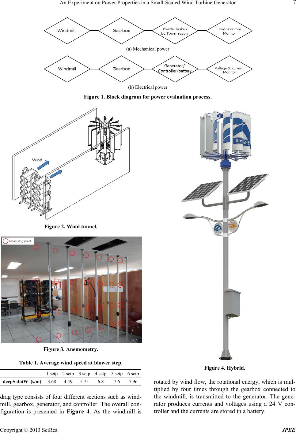 An Experiment on Power Properties in a Small-Scaled Wind Turbine Generator Copyright © 2013 SciRes. JPEE 7 (a) Mechanical power (b) Electrical power Figure 1. Block diagram for power evaluation process. Figure 2. Wind tunnel. Figure 3. Anemometry. Table 1. Average wind speed at blower step. 1 setp 2 setp 3 setp 4 setp 5 setp 6 setp dniWdeepS (s/m) 3.68 4.49 5.75 6.8 7.6 7.96 drag type consists of four different sections such as wind- mill, gearbox, generator, and controller. The overall con- figuration is presented in Figure 4. As the windmill is Figure 4. Hybrid. rotated by wind flow, the rotational energy, which is mul- tiplied by four times through the gearbox connected to the windmill, is transmitted to the generator. The gene- rator produces currents and voltages using a 24 V con- troller and the currents are stored in a battery. 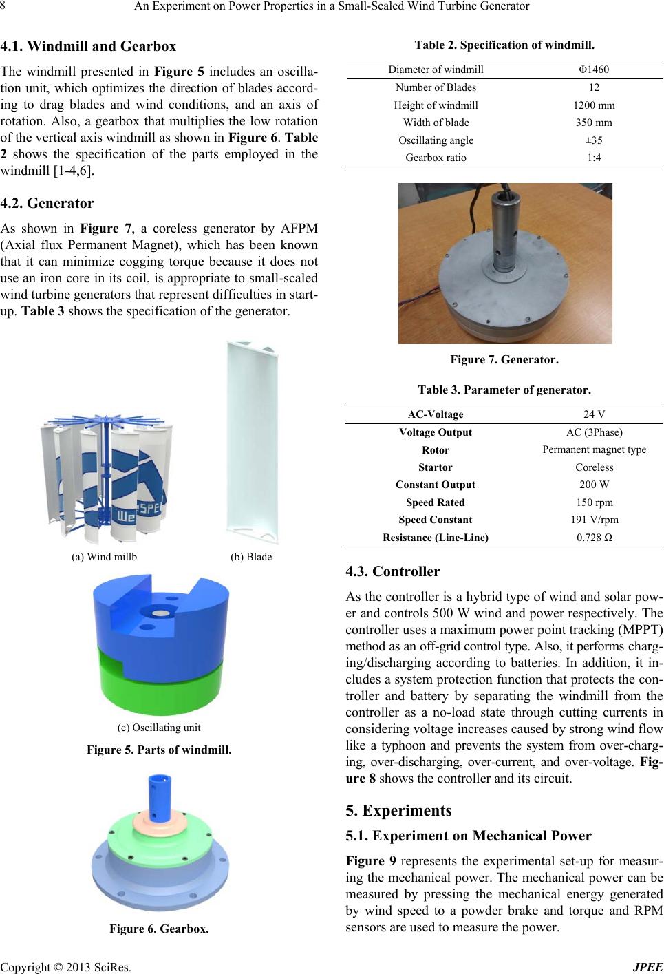 An Experiment on Power Properties in a Small-Scaled Wind Turbine Generator Copyright © 2013 SciRes. JPEE 8 4.1. Windmill and Gearbox The windmill presented in Figure 5 includes an oscilla- tion unit, which optimizes the direction of blades accord- ing to drag blades and wind conditions, and an axis of rotation. Also, a gearbox that multiplies the low rotation of the vertical axis windmill as shown in Figu re 6. Table 2 shows the specification of the parts employed in the windmill [1-4,6]. 4.2. Generator As shown in Figure 7, a coreless generator by AFPM (Axial flux Permanent Magnet), which has been known that it can minimize cogging torque because it does not use an iron core in its coil, is appropriate to small-scaled wind turbine generators that represent difficulties in start- up. Table 3 shows the specification of the generator. (a) Wind millb (b) Blade (c) Oscillating unit Figure 5. Parts of windmill. Figure 6. Gearbox. Table 2. Specification of windmill. Diameter of windmill Φ1460 Number of Blades 12 Height of windmill 1200 mm Width of blade 350 mm Oscillating angle ±35 Gearbox ratio 1:4 Figure 7. Generator. Table 3. Parameter of generator. AC-Voltage 24 V Voltage Output AC (3Phase) Rotor Permanent magnet type Startor Coreless Constant Output 200 W Speed Rated 150 rpm Speed Constant 191 V/rpm Resistance (Line-Line) 0.728 Ω 4.3. Controller As the controller is a hybrid type of wind and solar pow- er and controls 50 0 W wind and power respectively. The controller uses a maximum power point tracking (MPPT) method as an off-grid contro l typ e. Also , i t perfor ms charg- ing/discharging according to batteries. In addition, it in- cludes a system protection function that protects the con- troller and battery by separating the windmill from the controller as a no-load state through cutting currents in considering voltage increases caused by strong wind flow like a typhoon and prevents the system from over-charg- ing, over-discharging, over-current, and over-voltage. Fig- ure 8 shows the controller and its circuit. 5. Experiments 5.1. Experiment on Mechanical Power Figure 9 represents the experimental set-up for measur- ing the mechanical power. The mechanical power can be measured by pressing the mechanical energy generated by wind speed to a powder brake and torque and RPM sensors are used to measure the power. 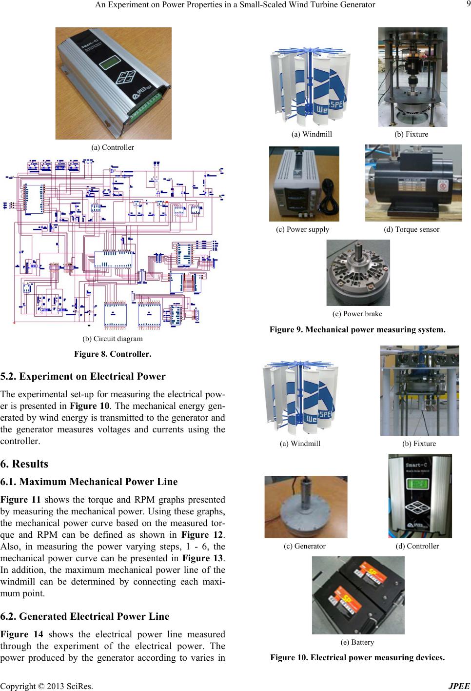 An Experiment on Power Properties in a Small-Scaled Wind Turbine Generator Copyright © 2013 SciRes. JPEE 9 (a) Controller (b) Circuit diagram Figure 8. Controller. 5.2. Experiment on Electrical Power The ex perimental set-up for measuring the electrical pow- er is presented in Figure 10. The mechanical energy gen- erated by wind energy is transmitted to the generator and the generator measures voltages and currents using the controller. 6. Results 6.1. Maximum Mechanical Power Line Figure 11 shows the torque and RPM graphs presented by measuring the mechanical power. Using these graphs, the mechanical power curve based on the measured tor- que and RPM can be defined as shown in Figure 12. Also, in measuring the power varying steps, 1 - 6, the mechanical power curve can be presented in Figure 13. In addition, the maximum mechanical power line of the windmill can be determined by connecting each maxi- mum point. 6.2. Generated Electrical P ower Line Figure 14 shows the electrical power line measured through the experiment of the electrical power. The power produced by the generator according to varies in (a) Windmill (b) Fixture (c) Power supply (d) Torque sensor (e) Power brake Figure 9. Mechanical power measuring system. (a) Windmill (b) Fixture (c) Generator (d) Controller (e) Battery Figure 10. Electrical power measuring devices. 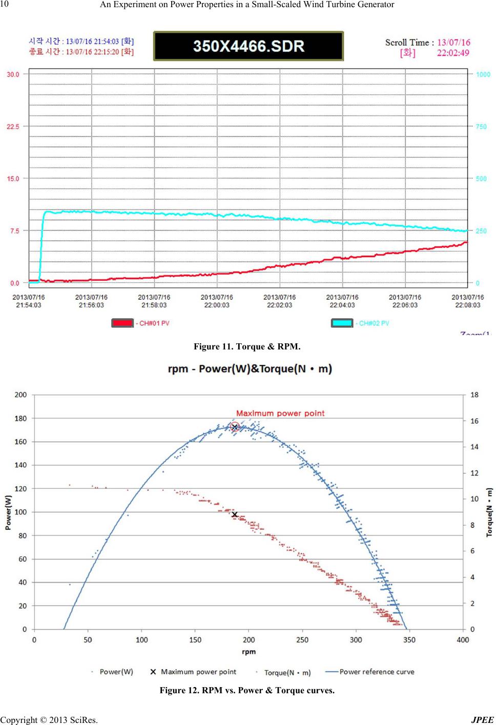 An Experiment on Power Properties in a Small-Scaled Wind Turbine Generator Copyright © 2013 SciRes. JPEE 10 Figure 11. Torque & RPM. Figure 12. RPM vs. Power & Torque curves. 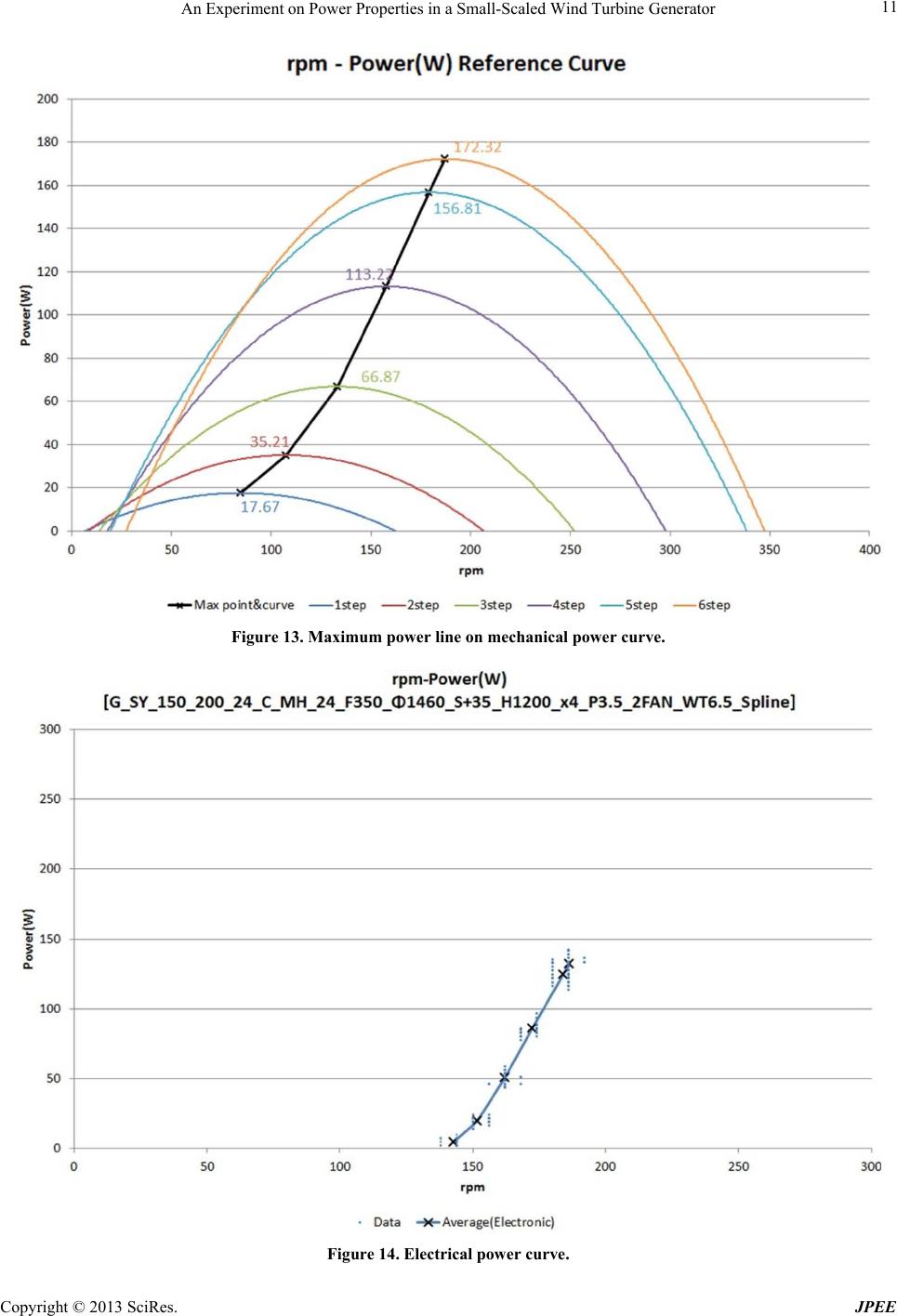 An Experiment on Power Properties in a Small-Scaled Wind Turbine Generator Copyright © 2013 SciRes. JPEE 11 Figure 13. Maximum power line on mechanical power curve. Figure 14. Electrical power curve. 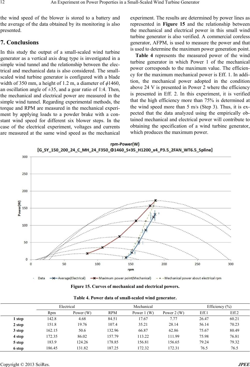 An Experiment on Power Properties in a Small-Scaled Wind Turbine Generator Copyright © 2013 SciRes. JPEE 12 the wind speed of the blower is stored to a battery and the average of the data obtained by its monitoring is also presented. 7. Conclusions In this study the output of a small-scaled wind turbine generator as a vertical axis drag type is investigated in a simple wind tunnel and the relationship between the elec- trical and mechanical data is also considered. The small- scaled wind turbine generator is configured with a blade width of 350 mm, a height of 1.2 m, a diameter of ϕ1460, an oscillation angle of ±35, and a gear ratio of 1:4. Then, the mechanical and electrical power are measured in the simple wind tunnel. Regarding experimental methods, the torque and RPM are measured in the mechanical experi- ment by applying loads to a powder brake with a con- stant wind speed for different six blower steps. In the case of the electrical experiment, voltages and currents are measured at the same wind speed as the mechanical experiment. The results are determined by power lines as represented in Figure 15 and the relationship between the mechanical and electrical power in this small wind turbine generator is also verified. A commercial coreless generator, AFPM, is used to measure the power and that is used to det erm ine t he m aximum power ge nerat i on point. Table 4 represents the measured power of the wind turbine generator in which Power 1 of the mechanical power corresponds to the maximum value. The efficien- cy for the maximum mechanical power is Eff. 1. In addi- tion, the mechanical power adopted in the condition above 24 V is presented in Power 2 where the efficiency is presented in Eff. 2. In this experiment, it is verified that the high efficiency more than 75% is determined at the wind speed more than 5 m/s (Step 3). Thus, it is ex- pected that the data analyzed using the empirically ob- tained mechanical and electrical power will contribute to obtaining the specification of a wind turbine generator, which produces the maximum power. Figure 15. Curves of mechanical and electrical powers. Table 4. Power data of small-scaled wind generator. Electrical Mechanical Efficiency (%) Rpm Power (W) RPM Power 1 (W) Power 2 (W) Eff.1 Eff.2 1 step 142.8 4.68 84.51 17.67 7.77 26.47 60.21 2 step 151.8 19.76 107.4 35.21 28.14 56.14 70.23 3 step 162.15 50.6 132.96 66.87 62.86 75.67 80.49 4 step 172.35 86.02 157.79 113.22 111.99 75.98 76.81 5 step 183.9 124.26 178.85 156.81 156.65 79.24 79.32 6 step 186.45 131.82 187.25 172.32 172.31 76.5 76.5 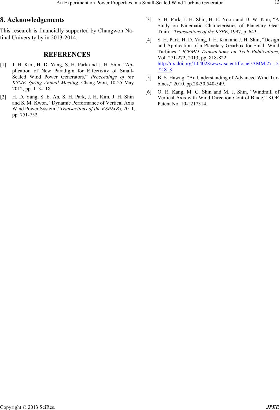 An Experiment on Power Properties in a Small-Scaled Wind Turbine Generator Copyright © 2013 SciRes. JPEE 13 8. Acknowledgements This research is financially supported by Changwon Na- tinal University by in 2013-2014. REFERENCES [1] J. H. Kim, H. D. Yang, S. H. Park and J. H. Shin, “Ap- plication of New Paradigm for Effectivity of Small- Scaled Wind Power Generators,” Proceedings of the KSME Spring Annual Meeting, Chang-Won, 10-25 May 2012, pp. 113-118. [2] H. D. Yang, S. E. An, S. H. Park, J. H. Kim, J. H. Shin and S. M. Kwon, “Dynamic Performance of Vertical Axis Wind Power System,” Transactions of the KSPE(B), 2011, pp. 751-752. [3] S. H. Park, J. H. Shin, H. E. Yoon and D. W. Kim, “A Study on Kinematic Characteristics of Planetary Gear Train,” Transactions of the KSPE, 1997, p. 643. [4] S. H. Park, H. D. Yang, J. H. Kim and J. H. Shin, “Design and Application of a Planetary Gearbox for Small Wind Turbines,” ICFMD Transactions on Tech Publications, Vol. 271-272, 2013, pp. 818-822. http://dx.doi.org/10.4028/www.scientific.net/AMM.271-2 72.818 [5] B. S. Hawng, “An Understanding of Advanced Wind Tur- bines,” 2010, pp.28-30,540-549. [6] O. R. Kang, M. C. Shin and M. J. Shin, “Windmill of Vertical Axis with Wind Direction Control Blade,” KOR Patent No. 10-1217314. |