

Paper Menu >>
Journal Menu >>
 Journal of Applied Mathematics and Physics, 2013, 1, 37-42 Published Online November 2013 (http://www.scirp.org/journal/jamp) http://dx.doi.org/10.4236/jamp.2013.16008 Open Access JAMP Effects of Noncircular Inlet on the Flow Struc tures in Turbulent Jets Won Hyun Kim, Tae Seon Park School of Mechanical Engineering, Kyungpook National University, Daegu, South Korea Email: [email protected] Received October 2013 ABSTRACT Turbulent jet flows with noncircular no zzle inlet are investigated by using a Reynolds Stress Model. In order to analyze the effects of noncircular inlet, the cross section of inlet are selected as circular, square, and equilateral trian gular shape. The jet half-width, vorticity thickness, and developments of the secondary flow are presented. From the result, it is con- firmed that the secondary flows of square and equilateral triangular nozzle are more vigorous than that of the circular jet. This development of secondary flows is closely related to the variations of vortical motions in axial and azimuthal di- rections. Keywords: Noncircular Turbulent Jet; Jet Half-Width; Vorticity Thickness; Secondary Flows 1. Introduction Turbulent jets are primary flow structures in many ap- plications such as jet pumps, ejectors, jet propuls ions and combustors etc. In such systems, the higher mixing rate is very critical for the system performance. So, various studies have been conducted to get the well-mixed states for turbulent jets. Among them, non-circular jets have been widely drawing attention as an efficient method for mixing flows. From a literature survey, previous studies were con- ducted on the turbulent flow of a jet issuing from differ- rently shaped nozzles [1-5]. From their results, it was found that the near-field flow of the jet is strongly influ- enced by the three-dimensional structure dependent on the loss of axisymmetric nature. From this structure, the mixing characteristics are improved. However, the de- tailed flowfields were weakly studied for the change of inlet nozzle. Although the flow structures of non-circular jets are basically similar to the circular jet flow, their mixing characteristics are quite dif ferent. First of all , at the plane perpendicular to the main streamwise flow, secondary flows are generated by the anisotropy of the turbulent stresses [6,7]. It can serve that the inlet flow has vortical motions. As the jet flow develops downstream, the inlet vortical motions are decayed and the vortical flows due to the circumferential variation of momentum difference grow. So, the above two factors are strongly related to non-circular jet flows near the inj ection plane. Such flow structure can affect the mixing characteristics and turbu- lent structures. However, unfortunately, the studies for examining the interrelation b etween the flow mixing and various vortices are very rare. In the present study, although various turbulence mod- els are available for turbulent flows of noncircular jet, a Reynolds stress model (RSM) is applied. To investigate the variation of the flow structure depending on the inlet nozzle, the nozzle cross-section is selected as circular, square, and triangular. The results are discussed with the flow mixing and peculiar characteristics of three jet flows. 2. Numerical Methods The governing equations for continuity and momentum are as follows ( ) 0 i i U x ρ ∂= ∂ (1) ( ) ij iij i ii UU U Puu xxx x ρµρ ∂∂ ∂∂ =−+ − ∂∂∂ ∂ (2) where Ui, P, μ, ρ , and ij uu represent the average ve- locity, pressure, viscosity, density, and the Reynolds stress, respectively. The flow of noncir cular nozzle is v ery anisotropic and the turbulence-driven flows are primary aspects. In the present study, a Reynolds stress model is adopted to re- produce the anisotropic quantities of noncircular jet 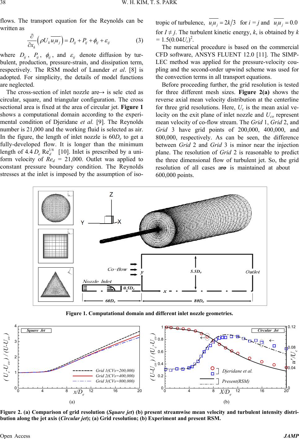 W. H. KIM, T. S. PARK Open Access JAMP 38 flows. The transport equation for the Reynolds can be written as ( ) k iji kjij ijij UD xuu P ερ φ ∂=+ ++ ∂ (3) where ij D , ij P , ij φ , and ij ε denote diffusion by tur- bulent, production, pressure-strain, and dissipation term, respectively. The RSM model of Launder et al. [8] is adopted. For simplicity, the details of model functions are neglected. The cross-section of inlet nozzle are → is selected as circular, squ are, and triangular configuration. The cross sectional area is fixed at the area of circular jet. Figure 1 shows a computational domain according to the experi- mental condition of Djeridane et al. [9]. The Reynolds number is 21,000 and the working fluid is selected as air. In the figure, the length of inlet nozzle is 60De to get a fully-developed flow. It is longer than the minimum length of 4.4 1/6 Re ed D [10]. Inlet is prescribed by a uni- form velocity of Red = 21,00 0. Outlet was applied to constant pressure boundary condition. The Reynolds stresses at the inlet is imposed by the assumption of iso- tropic of turbulence, 23 ij uu k= for i = j and 0.0 ij uu = for I ≠ j. The turbulent kinetic energy, k, is obtained by k = 1.5(0.04Uc)2. The numerical procedure is based on the commercial CFD software, ANSYS FLUENT 12.0 [11]. The SIMP- LEC method was applied for the pressure-velocity cou- pling and the second-order upwind scheme was used for the convection terms in all transport equations. Before proceeding further, the grid resolution is tested for three different mesh sizes. Figure 2(a) shows the reverse axial mean velocity distribution at the centerline for three grid resolutions. Here, Uc is the mean axial ve- locity on the exit plane of inlet nozzle and Uco represent mean velocity of co-flow stream. The Grid 1, Grid 2, and Grid 3 have grid points of 200,000, 400 ,00 0, and 800,000, respectively. As can be seen, the difference between Grid 2 and Grid 3 is minor near the injection plane. The resolution of Grid 2 is reasonable to predict the three dimensional flow of turbulent jet. So, the grid resolution of all cases are → is maintained at about 600,000 points. Figure 1. Computational domain and different inlet nozzle geometries. (a) (b) Figure 2. (a) Comparison of grid resolution (Square jet) (b) present streamwise mean velocity and turbulent intensity distri- bution along the jet axis (Circular jet); (a) Grid resolution; (b) Experiment and pr esent RSM. x/D e ( U c -U co ) / (U-U co ) 0 4 8121620 0 1 2 3 4 Grid 1(CVs=200,000) Grid 2(CVs=400,000) Grid 3(CVs=800,000) Square Jet Djeridane et al. Present(RSM) X/D e ( U-U co ) / (U c -U co ) u'/U c 04812 16 20 0 0.2 0.4 0.6 0.8 1 0 0.04 0.08 0.12 Circular Jet ← ← 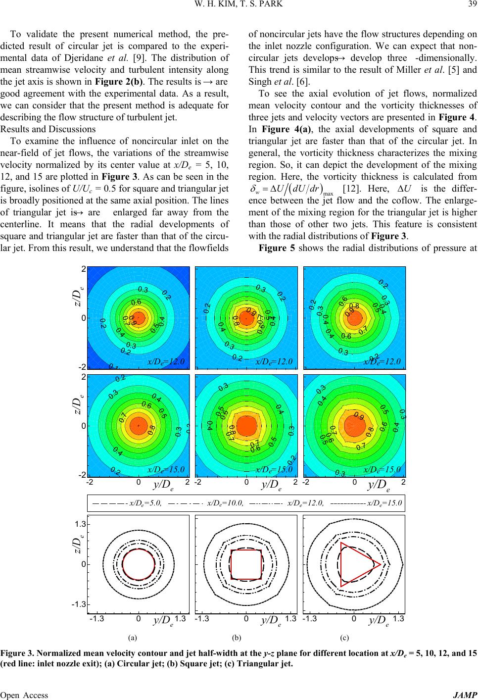 W. H. KIM, T. S. PARK Open Access JAMP 39 To validate the present numerical method, the pre- dicted result of circular jet is compared to the experi- mental data of Djeridane et al. [9]. The distribution of mean streamwise velocity and turbulent intensity along the jet axis is shown in Figure 2(b). The results is → are good agreement with the experimental data. As a result, we can consider that the present method is adequate for describing the flow structure of turbulent jet. Results and Discussions To examine the influence of noncircular inlet on the near-field of jet flows, the variations of the streamwise velocity normalized by its center value at x/De = 5, 10, 12, and 15 are plotted in Figure 3. As can be seen in the figure, isolines of U/Uc = 0.5 for square and triangular jet is broadly positioned at the same axial position. The lines of triangular jet is → are enlarged far away from the centerline. It means that the radial developments of square and triangular jet are faster than that of the circu- lar jet. From this result , we understand that the flowfields of noncircular jets have the flow structures depending on the inlet nozzle configuration. We can expect that non- circular jets develops → develop three-dimensionally. This trend is similar to the result of Miller et al. [5] and Singh et al. [6]. To see the axial evolution of jet flows, normalized mean velocity contour and the vorticity thicknesses of three jets and velocity vectors are presented in Figure 4. In Figure 4(a), the axial developments of square and triangular jet are faster than that of the circular jet. In general, the vorticity thickness characterizes the mixing region. So, it can depict the development of the mixing region. Here, the vorticity thickness is calculated from ( ) max w UdU dr δ = ∆ [12]. Here, U∆ is the differ- ence between the jet flow and the coflow. The enlarge- ment of the mixing region for the triangular jet is higher than those of other two jets. This feature is consistent with the radial distributions of Figure 3. Figure 5 shows the radial distributions of pressure at (a) (b) (c) Figure 3. Normalized mean velocity contour and jet half-width at the y-z plane for different location at x/De = 5, 10, 12, and 15 (red line: inlet nozzle exit); (a) Circular jet; (b) Square j et; (c) Triangular jet. 0.1 0.2 0.2 0.2 0.3 0.3 0.4 0.4 0.5 0.6 0.7 0.9 z/D e -2 0 2 x/D=12.0 e 0.2 0.2 0.2 0.3 0.3 0.3 0.4 0.4 0.4 0.5 0.6 0.6 0.7 0.8 0.9 x/D=12.0 e 0.2 0.2 0.2 0.3 0.3 0.4 0.4 0.5 0.6 0.7 0.8 0.9 x/D=12.0 e 0.3 0.3 0.3 0.4 0.4 0.5 0.5 0.6 0.6 0.7 0.7 0.8 0.9 y/D e -2 02 x/D=15.0 e 0.2 0.3 0.3 0.4 0.4 0.5 0.5 0.6 0.6 0.7 0.7 0.8 y/D e -2 02 x/D=15.0 e 0.2 0 2 0.2 0.3 0.3 0.4 0.4 0.5 0.6 0.7 0.8 y/D e z/D e -2 02 -2 0 2 x/D=15.0 e y/D e -1.3 01.3 y/D e -1.3 01.3 y/D e z/D e -1.3 01.3 -1.3 0 1.3 x/D=15.0x/D=5.0,x/D=10.0,x/D=12.0, ee ee 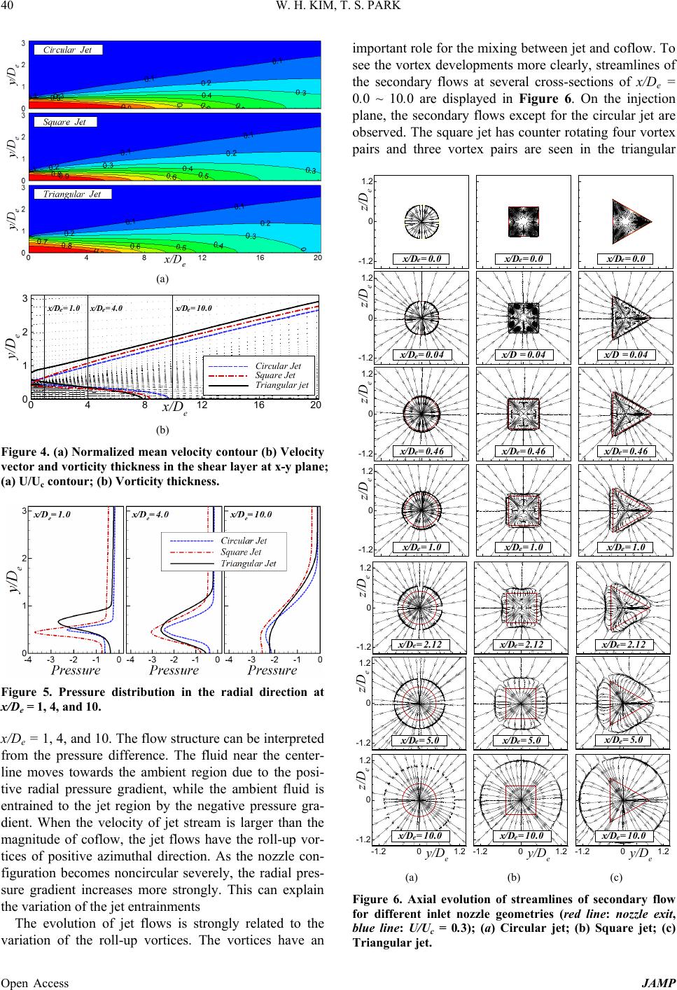 W. H. KIM, T. S. PARK Open Access JAMP 40 (a) (b) Figure 4. (a) Normalized mean velocity contour (b) Velocity vector and vorticity thickness in the shear layer at x-y plane; (a) U/Uc contour; (b) Vorticity t hickness . Figure 5. Pressure distribution in the radial direction at x/De = 1, 4, and 10. x/De = 1, 4, and 10. The flow structure can be interpreted from the pressure difference. The fluid near the center- line moves towards the ambient region due to the posi- tive radial pressure gradient, while the ambient fluid is entrained to the jet region by the negative pressure gra- dient. When the velocity of jet stream is larger than the magnitude of coflow, the jet flows have the roll-up vor- tices of positive azimuthal direction. As the nozzle con- figuration becomes noncircular severely, the radial pres- sure gradient increases more strongly. This can explain the variation of the jet entrainments The evolution of jet flows is strongly related to the variation of the roll-up vortices. The vortices have an important role for the mixing between jet and coflow. To see the vortex developments more clearly, streamlines of the secondary flows at several cross-sections of x/De = 0.0 ~ 10 .0 are displayed in Figure 6. On the injection plane, the secondary flows except for the circular jet are observed. The square jet has counter rotating four vortex pairs and three vortex pairs are seen in the triangular (a) (b) (c) Figure 6. Axial evolution of streamlines of secondary flow for different inlet nozzle geometries (red line: nozzle exit, blue line: U/Uc = 0.3); (a) Circular jet; (b) Square jet; (c) Triangular jet. x/De y/De 04812 16 20 0 1 2 3 Circular Jet Square Jet Triangular jet x/D =1.0x/D =10.0x/D =4.0 e ee x/D =1.0 e x/D =0.46 e x/D =0.04 x/D =0.0 e x/D =0.0 e z/D e -1.2 0 1.2 x/D =0.04 e x/D =0.04 x/D =0.46 e x/D =1.0 e z/D e -1.2 0 1.2 x/D =1.0 e z/D e -1.2 0 1.2 x/D =0.46 e z/D e -1.2 0 1.2 x/D =0.0 e y/D e -1.2 01.2 x/D =10.0 e y/D e -1.2 01.2 x/D =10.0 e x/D =5.0 e x/D =2.12 e x/D =2.12 e x/D =5.0 e z/D e -1.2 0 1.2 x/D =2.12 e z/D e -1.2 0 1.2 x/D =5.0 e y/D e z/D e -1.2 01.2 -1.2 0 1.2 x/D =10.0 e 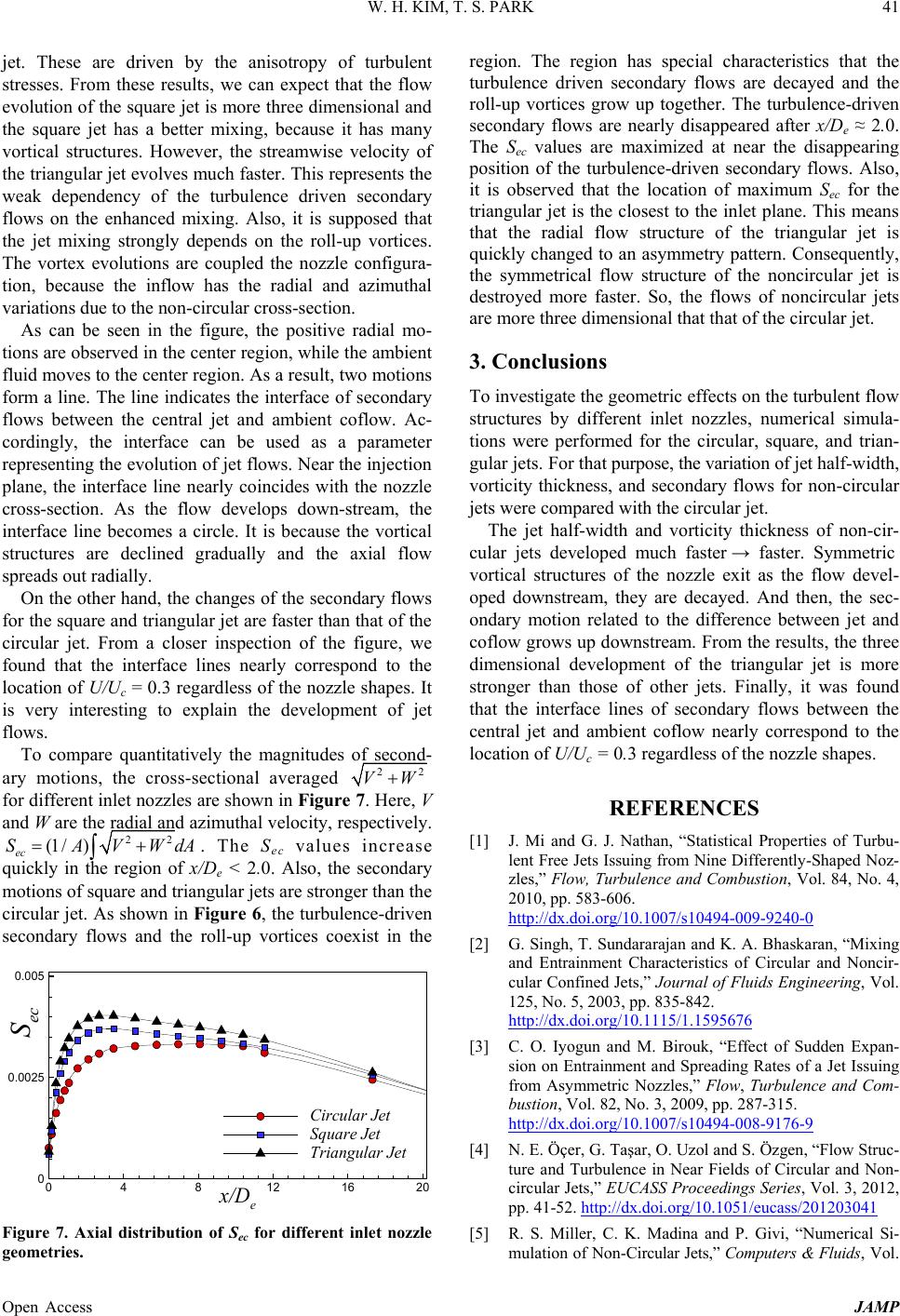 W. H. KIM, T. S. PARK Open Access JAMP 41 jet. These are driven by the anisotropy of turbulent stresses. From these results, we can expect that the flow evolution of the square jet is more three dimensional and the square jet has a better mixing, because it has many vortical structures. However, the streamwise velocity of the triangular jet evo lves much faster. This represents the weak dependency of the turbulence driven secondary flows on the enhanced mixing. Also, it is supposed that the jet mixing strongly depends on the roll-up vortices. The vortex evolutions are coupled the nozzle configura- tion, because the inflow has the radial and azimuthal variati ons due to t he n on -circular cross-section. As can be seen in the figure, the positive radial mo- tions are observed in the center region, while the ambient fluid moves to the center region. As a result, two motions form a line. The line indicates the interface of secondary flows between the central jet and ambient coflow. Ac- cordingly, the interface can be used as a parameter representing the evolution of jet flows. Near the injection plane, the interface line nearly coincides with the nozzle cross-section. As the flow develops down-stream, the interface line becomes a circle. It is because the vortical structures are declined gradually and the axial flow spreads out radially. On the other hand, the changes of the second ary flows for the square and triangular jet are faster than that of the circular jet. From a closer inspection of the figure, we found that the interface lines nearly correspond to the location of U/Uc = 0.3 regardless of the nozzle shapes. It is very interesting to explain the development of jet flows. To compare quantitatively the magnitudes of second- ary motions, the cross-sectional averaged 22 VW+ for different inlet no zzles are shown in Figure 7. Here, V and W are the radial and azimuthal velocity, respectively. 22 (1 /) ec SAVW dA= + ∫ . The Sec values increase quickly in the region of x/De < 2.0. Also, the secondary motions of square and triangular jets are stronger than the circular jet. As show n in Figure 6, the turbulenc e-driven secondary flows and the roll-up vortices coexist in the Figure 7. Axial distribution of Sec for different inlet nozzle geometries. region. The region has special characteristics that the turbulence driven secondary flows are decayed and the roll-up vortices grow up together. The turbulence-driven secondary flows are nearly disappeared after x/De ≈ 2.0. The Sec values are maximized at near the disappearing position of the turbulence-driven secondary flows. Also, it is observed that the location of maximum Sec for the triangular jet is the closest to the inlet plane. This means that the radial flow structure of the triangular jet is quickly changed to an asymmetry pattern. Consequently, the symmetrical flow structure of the noncircular jet is destroyed more faster. So, the flows of noncircular jets are more three dimensional that that of the circular jet. 3. Conclusions To investigate the geometric eff ects on the turbulent flow structures by different inlet nozzles, numerical simula- tions were performed for the circular, square, and trian- gular jets. For th at purpose, the variation of jet half-width, vorticity thickness, and secondary flows for non-circular jets were compared with the circular jet. The jet half-width and vorticity thickness of non-cir- cular jets developed much faster → faster. Symmetric vortical structures of the nozzle exit as the flow devel- oped downstream, they are decayed. And then, the sec- ondary motion related to the difference between jet and coflow grows up downstream. From the results, the thr ee dimensional development of the triangular jet is more stronger than those of other jets. Finally, it was found that the interface lines of secondary flows between the central jet and ambient coflow nearly correspond to the location of U/Uc = 0.3 regardless of the nozzle shapes. REFERENCES [1] J. Mi and G. J. Nathan, “Statistical Properties of Turbu- lent Free Jets Issuing from Nine Differently-Shaped Noz- zles,” Flow, Turbulence and Combustion, Vol. 84, No. 4, 2010, pp. 583-606. http://dx.doi.org/10.1007/s10494-009-9240-0 [2] G. Singh, T. Sundararajan and K. A. Bhaskaran, “Mixing and Entrainment Characteristics of Circular and Noncir- cular Confined Jets,” Journal of Fluids Engineering, Vol. 125, No. 5, 2003, pp. 835-842. http://dx.doi.org/10.1115/1.1595676 [3] C. O. Iyogun and M. Birouk, “Effect of Sudden Expan- sion on Entrainment and Spreading Rates of a Jet Issui ng from Asymmetric Nozzles,” Flow, Turbulence and Com- bustion, Vol. 82, No. 3, 2009, pp. 287-315. [4] N. E. Öçer, G. Taşar, O. Uzol and S . Özgen, “Flow Struc- ture and Turbulence in Near Fields of Circular and Non- circular Jets,” EUCASS Proceedings Series, Vol. 3, 2012, pp. 41-52. http://dx.doi.org/10.1007/s10494-008-9176-9 http://dx.doi.org/10.1051/eucass/201203041 [5] R. S. Miller, C. K. Madina and P. Givi, “Numerical Si- mulation of Non-Circular Jets,” Com puters & Fluids, Vol. x/D e S ec 04812 16 20 0 0.0025 0.005 CircularJet Square Jet Triangular Jet 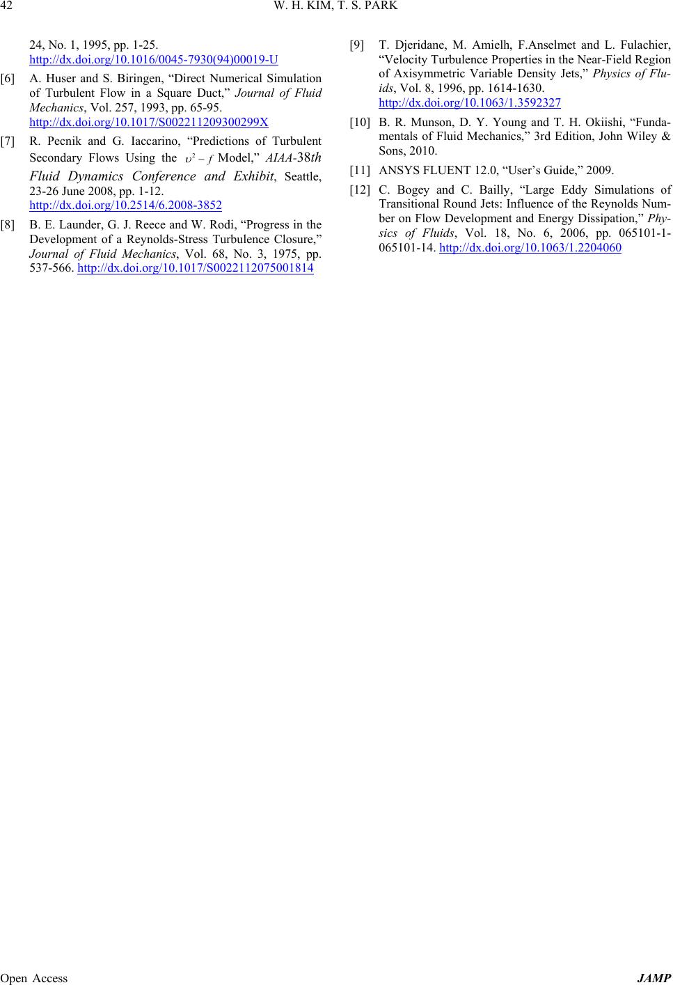 W. H. KIM, T. S. PARK Open Access JAMP 42 24, No. 1, 1995, pp. 1-25. [6] A. Huser and S. Biringen, “Direct Numerical Simulation of Turbulent Flow in a Square Duct,” Journal of Fluid Mechanics, Vol. 257, 1993, pp. 65-95. http://dx.doi.org/10.1016/0045-7930(94)00019-U [7] R. Pecnik and G. Iaccarino, “Predictions of Turbulent Secondary Flows Using the http://dx.doi.org/10.1017/S002211209300299X 2 f υ − Model,” AIAA-38th Fluid Dynamics Conference and Exhibit, Seattle, 23-26 June 2008, pp. 1-12. [8] B. E. Launder, G. J. Reece and W. Rodi, “Progress in the Development of a Reynolds-Stress Turbulence Closure,” Journal of Fluid Mechanics, Vol. 68, No. 3, 1975, pp. 537-566. http://dx.doi.org/10.2514/6.2008-3852 [9] T. Djer idane, M. Amielh, F.Anselmet and L. Fulachier, “Velocity Turbulence Properties in the Near-Field Region of Axisymmetric Variable Density Jets,” Physics of Flu- ids, Vol. 8, 1996, pp. 1614-1630. http://dx.doi.org/10.1017/S0022112075001814 http://dx.doi.org/10.1063/1.3592327 [10] B. R. Munson, D. Y. Young and T. H. Okiishi, “Funda- mentals of Fluid Mechanics,” 3rd Edition, John Wiley & Sons, 2010. [11] ANSYS FLUENT 12.0, “User’s Guide,” 2009. [12] C. Bogey and C. Bailly, “Large Eddy Simulations of Transitional Round Jets: Influence of the Reynolds Num- ber on Flow Development and Energy Dissipation,” Phy- sics of Fluids, Vol. 18, No. 6, 2006, pp. 065101-1- 065101-14. http://dx.doi.org/10.1063/1.2204060 |