

Paper Menu >>
Journal Menu >>
 Journal of Power and Energy Engineering, 2013, 1, 53-57 http://dx.doi.org/10.4236/jpee.2013.15008 Published Online October 2013 (http://www.scirp.org/journal/jpee) Copyright © 2013 SciRes. JPEE 53 Optimum Inclination Angles of Booster Mirrors and Solar Radiation Availability on the Horizontal and Inclined Box Type Solar Cookers V. P. Sethi1, K. Sumathy2, D. S. Pal3 1Department of Mechanical Engineering, Punjab Agricultural University, Ludhiana, Punjab India; 2Department of Mechanical Engi- neering, North Dakota State University, Fargo, USA; 3Department of Mathematics, Statistics and Physics, Punjab Agricultural Uni- versity, Ludhiana, Punjab India. Email: [email protected] Received October 2013 ABSTRACT Mathematical relations are developed to compute optimum inclination angle of booster mirror for horizontally placed cooker (λ) and for optimally inclined cooker (ψ) during all months (selected day) of the year at 30˚N latitude for max- imizing the reflected component of solar intensity onto the absorber plate of the cooker. A solar radiation model is also developed and used to compute the ratio of various solar intensities on horizontal, inclined and normal surface of the absorber plate for all months at 30˚N latitude. These ratios give a clear indication of greater solar rad iation availability on the optimally inclined cooker as compared to the horizontally placed cooker for faster cooking especially during winter months when solar radiation capture is small. Experimental validations have also been performed to access the accuracy of the developed relations and model. Keywords: Solar Radiation; Solar Cooker; Optimum Inclination; Booster Mirror 1. Introduction Many important modular studies have been performed on box type solar cookers till date to optimize their perfor- mance. Transient analysis was performed to get the over- all thermal performance of the box type solar cooker by [1]. A box type solar cooker which could perform well in clear sunny d ays was developed [2]. An obliqu e pan was also designed for putting the food material in tilted posi- tion. Parametric study of box type solar cooker was also performed with and without booster mirrors called ref- lectors [3]. Thermal performance of box type solar cook- er was tested and a test procedure was developed to test its performance using two figures of merit F1 and F2 [4]. An improved box type solar cooker with tilted absorb- ing surface was developed but the problem of placing the food material could not be solved [5]. Methods of testing and evaluating the advanced version of the box-type so- lar cooker were also developed [6]. A model for predic- tion of the cooking power of a solar cooker based on three controlled parameters (solar intercept area, overall heat loss coefficient, and absorber plate thermal conduc- tivity) and three uncontrolled variables (insolation, tem- perature difference, and load distribution) was developed [7]. The performance of solar cookers by analyzing the previously collected data was also evaluated [8]. The role of cooking vessel inside the cooker was established tak- ing into consideration its lid and the bottom surface [9, 10]. Cooking vessel design in cylindrical shape of box type was also improved and its heat transfer from the lid was also made faster to the food material placed inside the vessel [11,12]. A comparative experimental study of a box type solar cooker with two different cooking ves- sels was made [13]. Fins are shown to improve the heat transfer from the internal hot air of the cooker towards the interior of the vessel where the food to be cooked is placed. An optimally inclined box type solar cooker with modified cooking vessel design was presented [14]. The performance of optimally inclined cooker was consis- tently better as compared to conventional horizontally placed cooker in terms of higher solar radiation availabil- ity, absorber plate temperature, higher chamber tempera- ture and lesser cooking time. The review reveals that various researchers around the world have developed many improved solar cooker de- signs either by increasing the aperture (solar interception area), by using multiple reflectors, by changing the incli- nation of the solar cookers, by reducing the overall heat transfer coefficient, by increasing the conductive heat transfer of absorber plate and by modifying the cooking  Optimum Inclination Angles of Booster Mirrors and Solar Radiation Availability on the Horizontal and Inclined Box Type Solar Cookers Copyright © 2013 SciRes. JPEE 54 vessel design. In this study, a mathematical model is de- veloped to compute the optimum inclination angle of the booster mirror for horizontally placed and inclined cook- er for maximizing the reflected component of the solar radiation for better performance during all months and selected latitudes. 2. Description of Horizontal and Inclined Box Type Solar Cookers Two identical box type solar cookers of length 580 mm, width 300 mm and height 155 mm each were fabricated using galvanized iron sheet of 0.8mm thickness. One cooker was kept in horizontal position on ground (Figure 1) while the other cooker was kept on an optimally in- clined frame (Figure 2) in inclined pos ition. Each cooker has two top glass covers of 4 mm thickness and a booster mirror with a provision of altering the angle of inclina- tion. A round shape cylindrical cooking vessel of 175 mm diameter and 52 mm depth was placed inside the hori- zontally placed cooker. The designed parallelepiped cook- ing vessel was placed horizontally inside the inclined cooker for greater heat transfer to the food material. 3. Mathematical Model for Optimum Tilt Angle of the Booster Mirrors 3.1. Horizontally Placed Cooker Optimum tilt angle of the booster mirror is computed for all months and given latitude for maximizing the reflect- ed radiation component onto the absorber plate. In Figure 1, at the top edge A of the booster mirror Figure 1. Horizontal cooker with booster mirror at opti- mum inclined angle λ. Figure 2. Inclined cooker with booster mirror at optimum inclined an gle ψ. λ + θz + i = 90˚ (1) also 90CAB r∠ += (2) from Equations (1) and (2) z CAB λθ ∠=+ (3) If ray Ir1 strikes the top of the inclined reflector mirror at an angle λ + θz, then the line AC formed by reflected ray Rr1 reac hi ng t h e ed ge of t he uppe r gl ass c ove r al so ha s the same internal angle λ + θz, then in triangle ABC; , 90 90 2 z z CAB ABC and ACB θλ λ λθ ° ° ∠=+∠= ± ∠= −− Also mathematically we know that sin() sin(902)sin(90) zz BC ABAC θλ λθ λ °° = = +−− ± (4) Since AB= BC = W (width of the absorber plate) sin() sin(90 2) zz WW θλ λθ ° = +−− (5 ) Equation (5) gi ves the value of optimum tilt angle of the booster mirror λ for horizontally placed cooker ; 90 2 3 z θ λ ° − = (6) 3.2. Optimum Tilt Angle of the Booster Mirror for Inclined Cooker Optimum tilt of the booster mirror (ψ) in case of north facing reflector (Figure 2) of inclined solar water heater was give n by [ 15] and is used for inclined cooker as ψ = (π – β - 2ϕ + 2δ)/3 (7) The declination angle “δ” is computed using the given Equation (8) 360(284 ) 23.45sin 365 n δ + = (8) Booster mirror angle λ 15.5 cm 8cm 43 cm W=58cm 90±λ λ θz θ z +λ i r N o rmalto t hep l aneof reflection Incident ray,I ri R ef lecte dray, R ri C A B W Glass wool insulation -λ+λ North facing booste r mirror Ab so rbe r plate Parallelepiped cooking v esse l Double glass co ve r ψ +ψ -ψ Inc ident radiation Ii β, Inclined stand Double ste p frame  Optimum Inclination Angles of Booster Mirrors and Solar Radiation Availability on the Horizontal and Inclined Box Type Solar Cookers Copyright © 2013 SciRes. JPEE 55 where “n” is the number of days starting from January 1. 4. Solar Radiation Model Variation of effective width of the sun rays intercepted by the absorber plate in horizontal and inclined position of the cooker is shown in Figures 3(a) and (b). In ΔABC 90 s A α ∠= − cos(90 ) hs WW α =×− (9) Where αs can be computed using Equation (15). Hourly solar radiation incident on the inclined surface of the absorber plate depends upon the time of the day i.e. the hour angle ω (zero at noon, negative in the morning and positive in afternoon, varies by 15˚ after each hour), nth day of the year (starts from Januar y 1) i.e. declination angle δ, altitude angle αs with horizontal or zenith angle θz with vertical and surface azimuth angle γ (in northern hemisphere, it is zero for south facing surfaces, 180˚ for north facing surfaces, −90˚ for east facing and +90 for west facing surfaces), latitude angle φ of a place and tilt angle β of the s urface with horiz ont a l. Zenith angle of sun on the inclined absorber plate θi is given by [ 1 6] 1 cos[sin (sin coscos cos cossin ) cos (coscoscossin cos sin ) cos sinsinsin] ifg fg g θδ βδωβ δωβ δβ δ ωβ − = + +− + (10) Zenith angle of the sun with vertical (θz) and solar al- titude angle (αs) with horizontal at any time of the day and for any day of the year can be determined at any specific latitude location is given b y [16]. (a) (b) Figure 3. Variation of effective width of the sun rays inter- cepted by the absorber plate in (a) horizontal and (b) in- clined position. 1 cos(cos .cos .cossin.sin) z θφδ ωδφ − = + (11) ω = 15˚ (tsolar – 12) (12) The hour angle is 15˚ times the number of hours from solar noon. It is negative before noon, zero at noon and positive after 12. Intensity of extra terr es trial radiatio n Iext measure d on a plane normal to the radiation on the nth day of the year, 360 10034cos365 ext sc n II . = + (13) Value of direct normal solar radiation in terrestrial re- gion depe nds upon t urbidity fa c tor Tr of atmosphere [17]. exp 0.9 9.4sin r n exts T II α − = × + (14) Tr is known for different months and for different re- gions [18]. αs = 90 − θz (15) 'cos bn i II θ = (16a) cos hb nz II θ = (16b) The amount of diffuse radiation available on the in- clined surface can be known as (Tiwari, 2006) '' '2 cos 1cos/ 2 sin bi b dd ext sext II II II θβ α = +− (17) 1( )cos 3 dext nz I II θ = − The reflected component of total radiation is then com- puted as '2 sin/2 R gh I rI β = (1 8) Where “r” is the ground reflectivity (0.3) gh I bd II= + (1 9) On the horizontal surface of the absorber plate at solar noon. Total solar radiation falling on the inclined surface of the absorber plate at solar noon is given by Ii = Ib' + Id' + IR' (20) A computer program in C++ is developed and used for comput i ng the solar r adiati on flux on various surfa c e s. 5. Results and Discussion 5.1. Optimum Tilt Angles Optimum tilt angles computed for winter and summer months at 30˚N latitude are shown in Table 1. It shows W W Absorber plate in inclined position β Wh h W i Beam radiation on inclined surface (Iib) Beam radiation on normal surface (In) α s A B C 9 0 ° Beam radiation on horizontal surface (Ih)  Optimum Inclination Angles of Booster Mirrors and Solar Radiation Availability on the Horizontal and Inclined Box Type Solar Cookers Copyright © 2013 SciRes. JPEE 56 that for horizontal cook er, optimum inclination angle λ is 3.3˚, 1.2˚ and 8.2˚ outwards (+) from the vertical position (λ = 0˚) in October, February and March. It becomes 2.08˚, 5.6˚ and 4.2˚ inwards (−) from the vertical position during November, December and January due to greater solar zenith angle (θz). During summer, optimum inclina- tion angle λ is 20.8 ˚, 11.2˚, 6.8˚, 8.9 ˚, 16.7˚ and 27.6˚. In the case of inclined cooker, the optimum inclination an- gle ψ in winter months is 18.5˚, 12.1˚, 9.4˚, 11.0˚ 16.3˚ and 23.3˚. This variation is much higher in summer months as 41.5˚, 47.6˚, 50.6˚, 49.2˚, 44˚ and 36.2˚ for maximization of reflected component. 5.2. Solar Radiation Capture Ratios The ratio Wh/Wi is 0.62, 0.73, 0.84, 0.76, 0.65 and 0.60 during January, February, March, October, November and December which shows that inter- cepted width for solar radiation capture is much smaller for horizontal cooker as compared to in- clined cooker. The ratio of solar radiation intensity available on inclined to horizontal cooker (Ii/Igh) is 1.51, 1.33, 1.15, 1.26, 1.45 and 1.66 during January, February, March, October, November and Decem- ber which sho ws that in clined cook er receives much higher solar radiation intensity as compared to ho- rizontal cooker in winter months. The variation of horizontal versus normal surface and inclined ver- sus normal surface also shows that inclined cooker receives almost maximum possible radiation during all months of t he year as the ratio is al ways close to one. Whereas for horizontal cooker this variation is 0.59 to 1.00 during winter and summer months. 5.3. Experimental Validation The Figure 4 shows that the measured and predicted values of solar radiation intensities match well for hori- zontal as well as for inclined surface of absorber plate within 5% of the standard deviation. It shows that the developed model is accurate enough for making correct predictions for solar radiation availabilities at optimized inclination angles. Finally it can be concluded that inclined cooker has much better solar radiation capture during winter months for efficient cooking as compared to horizontally placed cooker at 30˚N latitude. Table 1. Optimum tilt angles computed for horizontal (λ) and inclined cooker (ψ) at 30˚N latitude during all months of the year. Winter Month and date, (n) Latitude (˚ N) 30 Summer Month and date, (n) Latitude (˚N) 30 θz λ ψ θz λ ψ Oct. 15, (288) 40.1 03.3 18.5 Apl, 15, (105) 20.8 16.1 41.5 Nov. 15, (319) 49.3 −2.08 12.1 May 15, (135) 11.2 22.5 47.6 Dec. 15, (349) 53.5 −5.6 9.4 June 15, (166) 6.8 25.5 50.6 Jan. 15, (15) 51.3 −4.2 11.0 July 15, (196) 8.9 24.0 49.2 Feb. 15, (46) 43.2 1.2 16.3 Aug. 15, (227) 16.7 18.8 44.0 Mar. 15, (74) 32.7 8.2 23.3 Sept. 15, (258) 27.6 11.4 36.2 Table 2. Shows the ratios of intercepted widths for horizontal (Wh) and inclined cooker (Wi) and solar radiation intensities on Horizontal (Igh), Inclined (Ii) and normal (In) surfac es for horizontal and incli ned cookers at 30˚N latitude during all months of year. Month and date, (Tr) Latitude 30˚N Month and date,(Tr) Latitude 30˚N Wh/Wi Ii/Igh Ihb/In Ib׳/In Wh/Wi Ii/Igh Ihb/In Ib׳/In Jan. 15, (3.1) 0.62 1.51 0.62 0.99 July 15, (4.3) 1.00 1.00 0.99 0.99 Feb. 15, (3.2) 0.73 1.33 0.73 1.00 Aug. 15, (4.2) 0.95 1.04 0.96 0.99 Mar. 15, (3.5) 0.84 1.15 0.84 1.00 Spt. 15, (3.9) 0.88 1.08 0.88 0.97 Apl, 15, (3.9) 0.93 1.05 0.93 1.00 Oct. 15, (3.6) 0.76 1.26 0.76 0.98 May 15, (4.1) 0.98 1.02 0.98 1.00 N ov. 15, (3.3) 0.65 1.45 0.65 0.99 June 15, (4.2) 1.00 1.00 0.99 0.99 Dec. 15, (3.1) 0.60 1.66 0.59 0.99 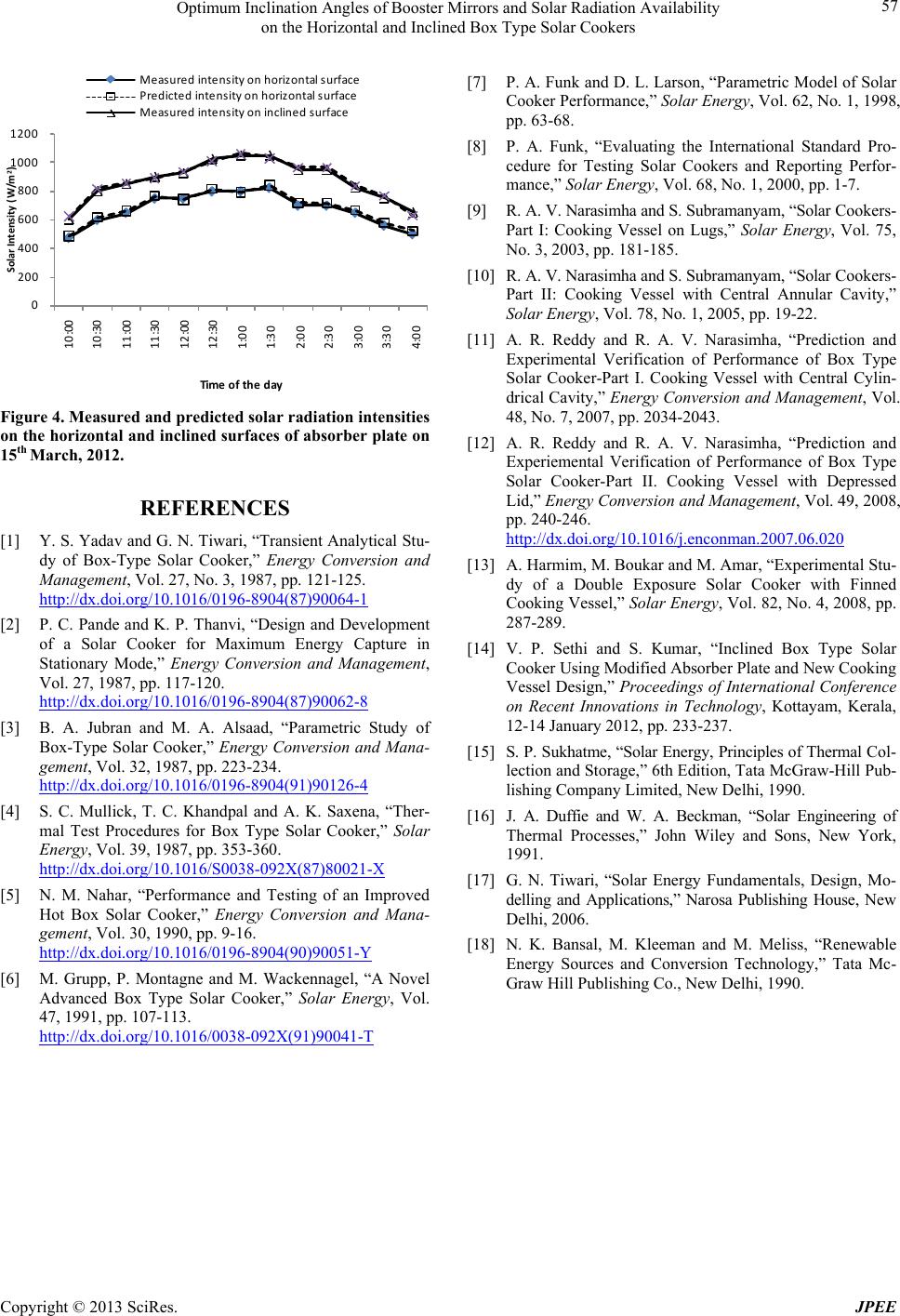 Optimum Inclination Angles of Booster Mirrors and Solar Radiation Availability on the Horizontal and Inclined Box Type Solar Cookers Copyright © 2013 SciRes. JPEE 57 Figure 4. Measured and predict ed sol ar r adi ation i nte nsit ie s on the horizontal and inclined surfaces of absorber plate on 15th March, 2012. REFERENCES [1] Y. S. Yada v and G. N. Tiwari, “Transient Analytical St u- dy of Box-Type Solar Cooker,” Energy Conversion and Management, Vol. 27, No. 3, 1987, pp. 121-125. http://dx.doi.org/10.1016/0196-8904(87)90064-1 [2] P. C. Pande and K. P. Thanvi, “Design and Development of a Solar Cooker for Maximum Energy Capture in Stationary Mode,” Energy Conversion and Management, Vol. 27, 1987, pp. 117-120. http://dx.doi.org/10.1016/0196-8904(87)90062-8 [3] B. A. Jubran and M. A. Alsaad, “Parametric Study of Box-Type Solar Cooker,” Energy Conversion and Mana- gement, Vol. 32, 1987, pp. 223-234. http://dx.doi.org/10.1016/0196-8904(91)90126-4 [4] S. C. Mullick, T. C. Khandpal and A. K. Saxena, “Ther- mal Test Procedures for Box Type Solar Cooker,” Solar Energy, Vol. 39, 1987, pp. 353-360. http://dx.doi.org/10.1016/S0038-092X(87)80021-X [5] N. M. Nahar, “Performance and Testing of an Improved Hot Box Solar Cooker,” Energy Conversion and Mana- gement, Vol. 30, 1990, pp. 9-16. http://dx.doi.org/10.1016/0196-8904(90)90051-Y [6] M. Grupp, P. Montagne and M. Wackennagel, “A Novel Advanced Box Type Solar Cooker,” Solar Energy, Vol. 47, 1991, pp. 107-113. http://dx.doi.org/10.1016/0038-092X(91)90041-T [7] P. A. Funk and D. L. Larson, “Parametric Model of Solar Cooker Performance,” Solar Energy, Vol. 62, No. 1, 1998, pp. 63-68. [8] P. A. Funk, “Evaluating the International Standard Pro- cedure for Testing Solar Cookers and Reporting Perfor- mance,” Solar Energy, Vol. 68, No. 1, 2000, pp. 1-7. [9] R. A. V. Narasimha and S. Subramanyam, “Solar Cookers- Part I: Cooking Vessel on Lugs,” Solar Energy, Vol. 75, No. 3, 2003, pp. 181-185. [10] R. A. V. Narasimha and S. Subramanyam, “Solar Cookers- Part II: Cooking Vessel with Central Annular Cavity,” Solar Energy, Vol. 78, No. 1, 2005, pp. 19-22. [11] A. R. Reddy and R. A. V. Narasimha, “Prediction and Experimental Verification of Performance of Box Type Solar Cooker-Part I. Cooking Vessel with Central Cylin- drical Ca vity,” Energy Conversion and Management, Vol. 48, No. 7, 2007, pp. 2034-2043. [12] A. R. Reddy and R. A. V. Narasimha, “Prediction and Experiemental Verification of Performance of Box Type Solar Cooker-Part II. Cooking Vessel with Depressed Lid,” Energy Conversion and Management, Vol. 49, 2008, pp. 240-246. http://dx.doi.org/10.1016/j.enconman.2007.06.020 [13] A. Harmim, M. Boukar and M. Amar, “Experimental Stu- dy of a Double Exposure Solar Cooker with Finned Cooking Vessel,” Solar Energy, Vol. 82, No. 4, 2008, pp. 287-289. [14] V. P. Sethi and S. Kumar, “Inclined Box Type Solar Cooker Using Modified Absorber Plate and Ne w Cooking Vessel Design,” Proceedings of International Conference on Recent Innovations in Technology, Kottayam, Kerala, 12-14 January 2012, pp. 233-237. [15] S. P. Sukhatme, “Solar Energy, Principles o f Thermal Col- lection and Storage,” 6th Edition, Tata McGraw-Hill Pub- lishing Company Limited, New Delhi, 1990. [16] J. A. Duffie and W. A. Beckman, “Solar Engineering of Thermal Processes,” John Wiley and Sons, New York, 1991. [17] G. N. Tiwari, “Solar Energy Fundamentals, Design, Mo- delling and Applications,” Narosa Publishing House, New Delhi, 2006. [18] N. K. Bansal, M. Kleeman and M. Meliss, “Renewable Energy Sources and Conversion Technology,” Tata Mc- Graw Hill Publishing Co., New Delhi, 1990. 0 200 400 600 800 1000 1200 Solar Intensity (W/m 2 ) Time of the day Measured intensity on horizontal surface Predicted intensity on horizontal surface Measured intensity on inclined surface 10:00 10:30 11:00 11:30 12:00 12:30 1 :00 1 :30 2 :00 2 :30 3 :00 3 :30 4 :00 |