

Paper Menu >>
Journal Menu >>
 Journal of Computer and Communications, 2013, 1, 46-50 Published Online November 2013 (http://www.scirp.org/journal/jcc) http://dx.doi.org/10.4236/jcc.2013.16009 Open Access JCC Implementation of RANSAC Algorithm for Feature-Based Image Registr ati on Lan-Rong Dung1, Chang-Min Huang1, Yin-Yi Wu2 1Departmentof Electrical and Computer Engineering, National Chiao Tung University, Hsinchu; 2Chung-Shan Institute of Science Technology, Tao-Yuan. Email: [email protected] Received October 2013 ABSTRACT This paper describes the hardware implementation of the RANdom Sample Consensus (RANSAC) algorithm for fea- tured-based image registration applications. The Multiple-Input Signature Register (MISR) and the index register are used to achieve the random sampling effect. The systolic array architecture is adopted to implement the forward elimi- nation step in the Gaussian elimination. The computational complexity in the forward elimination is reduced by sharing the coefficient matrix. As a result, the area of the hardware cost is reduced by more than 50%. The proposed architec- ture is realized using Verilog and achieves real-time calculation on 30 fps 1024 * 1024 video strea m on 100 MHz clock. Keywords: RANSAC; Image Registration; VLSI; Image Processing 1. Introduction Image registration is the process of precisely overlaying two (or more) images of the same area through geometr- ically aligning common features (or control points) iden- tified in the images [1,2]. Image registration can be more generalized as a mapping between two images both spa- tially and with respect to intensity [3]. Th e images can be taken at different times, from different viewpoints or by different sensors. Therefore, image registration tech- niques normally can be grouped into four categories: multi-modal registration, template registration, multi- viewpoints registration and multi-temporal registration [3,4]. The registered images can be used for different pur- poses, such as (1) integrating or fusing information taken from different sensors, (2) finding changes in the images taken at different times or under different conditions, (3) inferring three-dimensional (3-D) information from im- ages in which either the camera or the objects in the scene have moved and (4) for model-based object recog- nition [ 3]. Normally, image registr ation consists of fo ur steps: (1) feature detection and extraction, (2) feature matching, (3) transformation function fitting and (4) image transforma- tion and image resampling [2,4]. For the robust estima- tion of transformation function, RANdomSAmple Con- sensus (RANSAC) algorithm [5] has been used to handle mapping features in presence of outliers successfully. It also has been showed that it works for robust estimation of mapping functions in the automated image registration [6-8]. This paper proposes a hardware architecture for the RANSAC algorithm. The design adopts the Multiple- input signature register (MISR) and the index register to achieve the effect of random sampling. The matrix tri- angularization of the forward elimination is realized by systolic array. Sharing the coefficient matrix not only reduces the computational complexity but also saves the area of hardware cost. 2. Main Stages of RANSAC Algorithm This section briefly introduces the RANSAC algorithm and previous work for hardware implementation. Figure 1 shows the computational flow of the RANSAC algo- rithm. The source images need to be registered together after feature detection and matching. The RANSAC al- gorithm can be applied to get the homography of each image pair. Four initial putative feature matches are se- lected in the random selection step of each iteration in RANSAC [5], and a correct homography can be got after the final iteration if they are the real inliers. Each RAN- SAC iteration works in the following three steps: • Select a random sample of four feature matches. • Select a random sample of four feature matches. • Compute the number of inliers consistent with Hby a distance threshold. 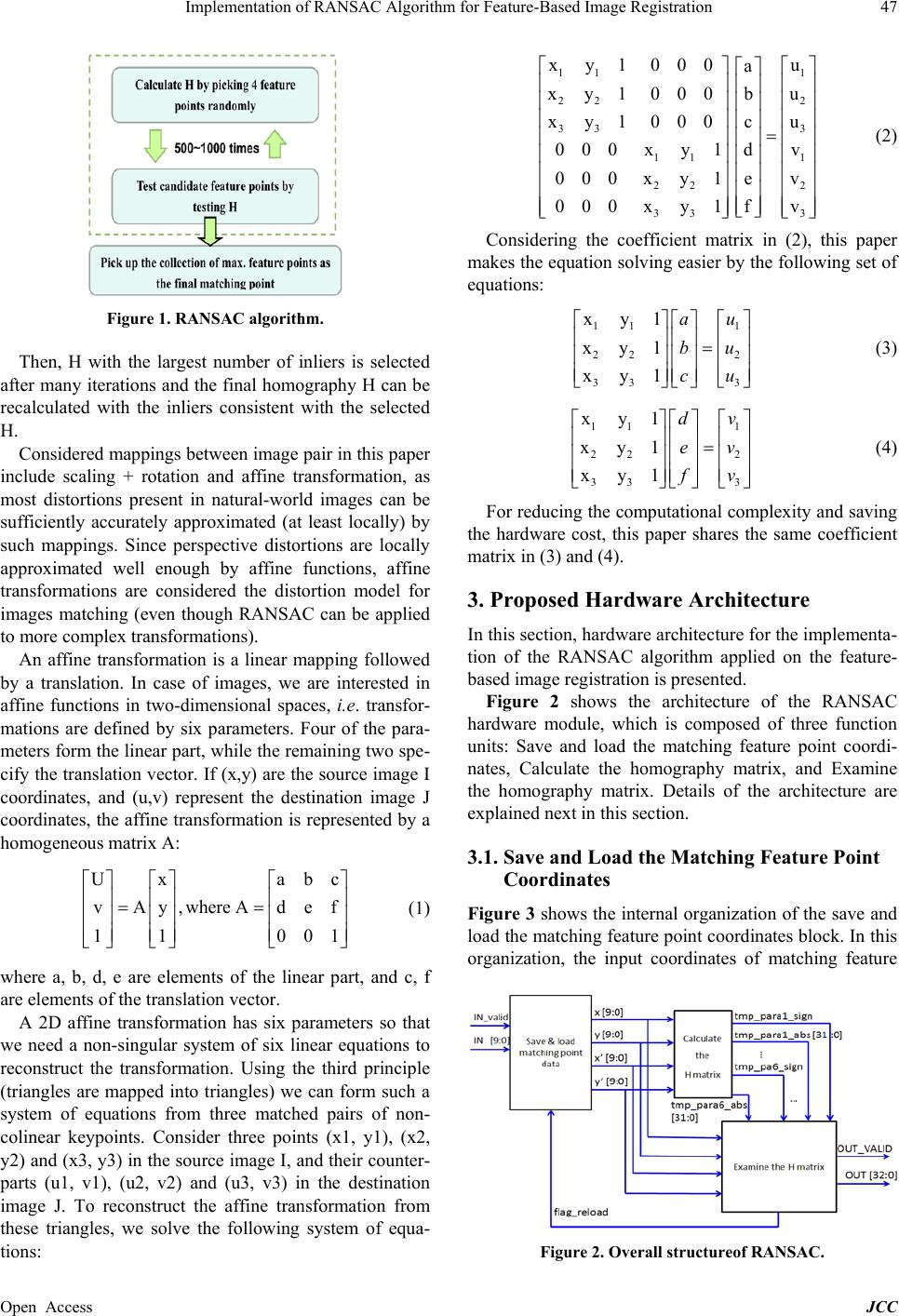 Implementation of RANSAC Algorithm for Feature-Based Image Registration Open Access JCC 47 Figure 1. RANSAC algorithm. Then, H with the largest number of inliers is selected after many iterations and the final homography H can be recalculated with the inliers consistent with the selected H. Considered mappings between image pair in this paper include scaling + rotation and affine transformation, as most distortions present in natural-world images can be sufficiently accurately approximated (at least locally) by such mappings. Since perspective distortions are locally approximated well enough by affine functions, affine transformations are considered the distortion model for images matching (even though RANSAC can be applied to more complex transformations). An affine transformation is a linear mapping followed by a translation. In case of images, we are interested in affine functions in two-dimensional spaces, i.e. transfor- mations are defined by six parameters. Four of the para- meters form the linear part, while the remaining two spe - cify the translation vector. If (x,y) are the source image I coordinates, and (u,v) represent the destination image J coordinates, the affine transformation is represented by a homoge ne o us matri x A: U xabc vAy,where Adef 1 1001 = = (1) where a, b, d, e are elements of the linear part, and c, f are elements of the translation vector. A 2D affine transformation has six parameters so that we need a non-singular system of six linear equations to reconstruct the transformation. Using the third principle (triangles are mapped into triangles) we can form such a system of equations from three matched pairs of non- colinear keypoints. Consider three points (x1, y1), (x2, y2) and (x3, y3) in the source image I, and their counter- parts (u1, v1), (u2, v2) and (u3, v3) in the destination image J. To reconstruct the affine transformation from these triangles, we solve the following system of equa- tions: 11 1 22 2 33 3 11 1 22 2 33 3 xy1000u a xy1000u b xy1000u c 000xy1 dv 000xy1 ev 000xy1fv = (2) Considering the coefficient matrix in (2), this paper makes the equation solving easier by the following set of equations: 11 1 22 2 33 3 x y1 x y1 x y1 au bu cu = (3) 11 1 22 2 33 3 x y1 x y1 x y1 dv ev fv = (4) For reducing the computational complexity and saving the hardware cost, this paper shares the same coefficient matrix in (3) and (4). 3. Proposed Hardware Architecture In this section, hardw are architecture for the implementa - tion of the RANSAC algorithm applied on the feature- based image registration is presented. Figure 2 shows the architecture of the RANSAC hardware module, which is composed of three function units: Save and load the matching feature point coordi- nates, Calculate the homography matrix, and Examine the homography matrix. Details of the architecture are explained next in this secti on. 3.1. Save and Load the Matching Feature Point Coordinates Figure 3 shows the internal organization of the save and load the matching feature point coordinates block. In this organization, the input coordinates of matching feature Figure 2. Overall structureof RANSAC. 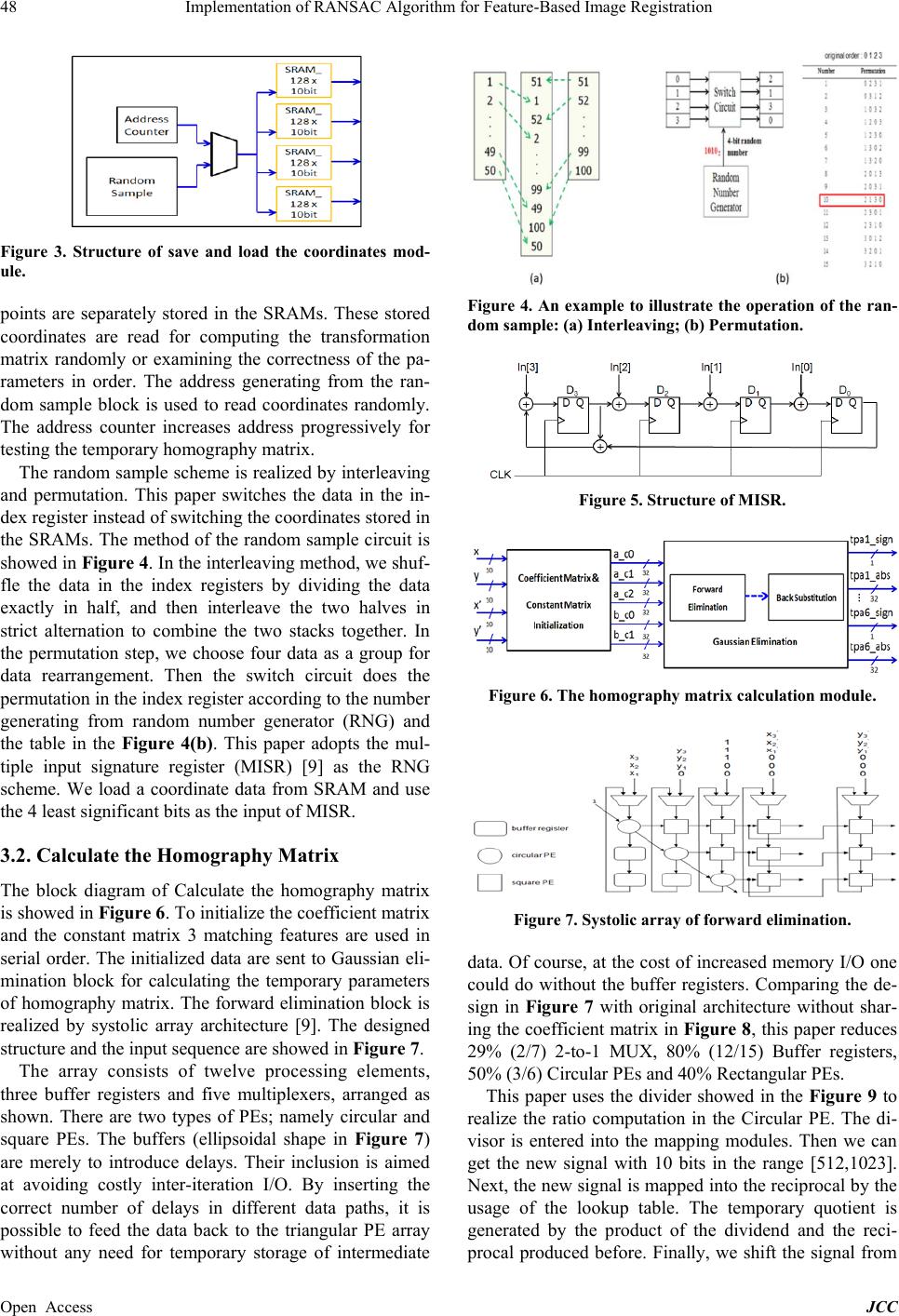 Implementation of RANSAC Algorithm for Feature-Based Image Registration Open Access JCC 48 Figure 3. Structure of save and load the coordinates mod- ule. points are separately stored in the SRAMs. These stored coordinates are read for computing the transformation matrix randomly or examining the correctness of the pa- rameters in order. The address generating from the ran- dom sample block is used to read coordinates randomly. The address counter increases address progressively for testing the temporary homography matrix. The random sample scheme is realized by interleaving and permutation. This paper switches the data in the in- dex register instead of switching the coordinates stored in the SRAMs. The method of the random sample circuit is showed in Figure 4. In the interleaving method, we shuf- fle the data in the index registers by dividing the data exactly in half, and then interleave the two halves in strict alternation to combine the two stacks together. In the permutation step, we choose four data as a group for data rearrangement. Then the switch circuit does the permutation in the index register according to the number generating from random number generator (RNG) and the table in the Figure 4(b). This paper adopts the mul- tiple input signature register (MISR) [9] as the RNG scheme. We load a coordinate data from SRAM and use the 4 least significant bits as the input of MISR. 3.2. Calculate the Homography Matrix The block diagram of Calculate the homography matrix is showed in Figure 6. To initialize the coefficient matrix and the constant matrix 3 matching features are used in serial order. The initialized data are sent to Gaussian eli- mination block for calculating the temporary parameters of homography matrix. The forward elimination block is realized by systolic array architecture [9]. The designed structure and the input sequence are showed in Figure 7. The array consists of twelve processing elements, three buffer registers and five multiplexers, arranged as shown. There are two types of PEs; namely circular and square PEs. The buffers (ellipsoidal shape in Figure 7) are merely to introduce delays. Their inclusion is aimed at avoiding costly inter-iteration I/O. By inserting the correct number of delays in different data paths, it is possible to feed the data back to the triangular PE array without any need for temporary storage of intermediate Figure 4. An example to illustrate the operation of the ran- dom sample: (a) Interleaving; (b) Permutation. Figure 5. Structure of MISR. Figure 6. The homography matrix calculation module. Figure 7. Systolic array of forward elimination. data. Of course, at the cost of increased memory I/O one could do without the buffer registers. Comparing the de- sign in Figure 7 with original architecture without shar- ing the coefficient matrix in Figure 8, this paper reduces 29% (2/7) 2-to-1 MUX, 80% (12/15) Buffer registers, 50% (3/6) Circular PEs and 40% Rectangular PEs. This paper uses the divider showed in the Figure 9 to realize the ratio computation in the Circular PE. The di- visor is entered into the mapping modules. Then we can get the new signal with 10 bits in the range [512,1023]. Next, the new signal is mapped into the reciprocal by the usage of the lookup table. The temporary quotient is generated by the product of the dividend and the reci- procal produced before. Finally, we shift the signal from 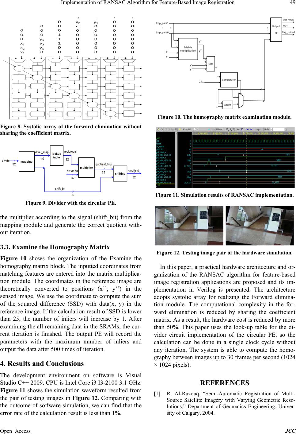 Implementation of RANSAC Algorithm for Feature-Based Image Registration Open Access JCC 49 Figure 8. Systolic array of the forward elimination without sharing the coefficient matrix. Figure 9. Divider with the circular PE. the multiplier according to the signal (shift_bit) from the mapping module and generate the correct quotient with- out iteration. 3.3. Examine the Homography Matrix Figure 10 shows the organization of the Examine the homography matrix block. The inputted coordinates from matching features are entered into the matrix multiplica- tion module. The coordinates in the reference image are theoretically converted to positions (x’’, y’’) in the sensed image. We use the coordinate to compute the sum of the squared difference (SSD) with data(x, y) in the reference image. If the calculation result of SSD is lower than 25, the number of inliers will increase by 1. After examining the all remaining data in the SRAMs, the cur - rent iteration is finished. The output PE will record the parameters with the maximum number of inliers and output t he da t a after 500 times of iteration. 4. Results and Conclusions The development environment on software is Visual Studio C++ 2009. CPU is Intel Core i3 I3-2100 3.1 GHz. Figure 11 shows the simulation waveform resulted from the pair of testing images in Figure 12. Comparing with the outcome of software simulation, we can find that the error rate of the calculation result is less than 1%. Figure 10. The homography matrix examination module. Figure 11. Simulation results of RANSAC implementation. Figure 12. Testing image pair of the hardware simulation. In this paper, a practical hardware architecture and or- ganization of the RANSAC algorithm for feature-based image registration applications ar e proposed and its im- plementation in Verilog is presented. The architecture adopts systolic array for realizing the Forward elimina- tion module. The computational complexity in the for- ward elimination is reduced by sharing the coefficient matrix. As a result, the hardware cost is reduced by more than 50%. This paper uses the look-up table for the di- vider circuit implementation of the circular PE, so the calculation can be done in a single clock cycle without any iteration. The system is able to compute the homo- graphy between images up to 30 frames per second (1024 × 1024 pixel s). REFERENCES [1] R. Al-Ruzouq, “Semi-Automatic Registration of Multi- Source Satellite Imagery with Varying Geometric Reso- lutions,” Department of Geomatics Engineering, Univer- sity of Calgary, 2004.  Implementation of RANSAC Algorithm for Feature-Based Image Registration Open Access JCC 50 [2] Z. Xiong and Y. Zhang, “A Critical Review of Image Registration Methods,” International Journal of Image and Data Fusion, Vol. 1, N o. 2, 2010, pp. 137-158. http://dx.doi.org/10.1080/19479831003802790 [3] L. G. Brown, “A Survey of Image Registration Tech- niques,” ACM Computing Surveys (CSUR), Vol. 24, No. 4, 1992, pp. 325-376. [4] B. Zitova and J. Flusser, “Image Re gistration Methods: A Survey,” Image and Vision Computing, Vol. 21, No. 11, 2003, pp. 977-1000. http://dx.doi.org/10.1016/S0262-8856(03)00137-9 [5] M. A. Fischler and R. C. Bolles, “Random Sample Con- sensus: A Paradigm for Model Fitting with Applications to Image Analysis and Automated Cartography,” Com- munications of the ACM, Vol. 24, No. 6, 1981, pp. 381- 395. http://dx.doi.org/10.1145/358669.358692 [6] T. Kim and Y.-J. Im, “Automatic Satellite Image Regis- tration by Combination of Matching and Random Sample Consensus,” IEEE Transactions on Geoscience and Re- mote Sensing, Vol. 41, No. 5, 2003, pp. 1111-1117. http://dx.doi.org/10.1109/TGRS.2003.811994 [7] M. Brown and D. G. Lowe, “Automatic Panoramic Image Stitching Using Invariant Features,” International Jour- nal of Computer Vision, Vol. 74, No. 1, 2007, pp. 59-73. http://dx.doi.org/10.1007/s11263-006-0002-3 [8] M. Brown and D. G. Lowe, “Recognising Panoramas,” In ICCV, Vol. 2, October 2003, pp. 1218-1225. [9] F. Elguibaly and M. W. El-Kharashi, “Multiple-Input Signature Registers: An Improved Design,” Communica- tions, Computers and Signal Processing, Vol. 2, Aug. 1997, pp. 519-522. |