

Paper Menu >>
Journal Menu >>
 Energy and Power Engineering, 2013, 5, 1456-1462 doi:10.4236/epe.2013.54B276 Published Online July 2013 (http://www.scirp.org/journal/epe) Energization of a Half-Wavelength Transmission Line - Pr e-Operational Transients Studies Camilo Machado Jr1, Marcelo Maia2, Eden Carvalho Jr3, Maria C. Tavares4, João B. Gertrudes5, Elson C. Gomes4, Walmir Freitas4, Marcos A. Paz5, Fernando A. Moreira6, Carlos A. Floriano1, Vanderlei G. Machado1, Aniela M. Mendes1 1ELETRONORTE -Brasília, Brazil 2CHESF, Recife, Brazil 3ENTE, São Paulo, Brazil 4University of Campinas, Campinas, Brazil 5State University of Feira de Santana, Feira de Santana, Brazil 6Federal University of Bahia, Salvador, Brazil Email: [email protected], mj[email protected], ej[email protected], Received April, 2013 ABSTRACT In the present paper the main results of the pre-operational studies related to the energization maneuver of a Half-Wavelength Transmission Line (AC-Link), are presented. The simulations were performed in PSCAD with actual Brazilian system data. Specifically the following studies were performed: electromagnetic transient studies of energiza- tion maneuver considering no fault and the occurrence of fault along the trunk; dynamic analysis of generator units that will energize the AC-Link; TRV on the circuit-breaker that will energize the trunk. The main conclusion is that the AC-Link energization experiment can be implemented without jeopardizing or causing time-life reduction of the equipment involved in the experiment, which comprises the generator unit that will energize the trunk, the step-up transformer, the arresters that will be kept during the experiments, as well as the circuit-breaker that will energize and then trip the AC-Link. Keywords: Electromagnetic Transients; Half-wavelength Transmission; AC-Link; Energization Test; Dynamic Analysis; TRV; Faults 1. Introduction According to Brazilian Institute of Geography and Statis- tics (IBGE) on the last 10 years Brazilian population has grown 1.17 % per year, totalizing 12.48 % for the last decade. This growth aligned to the Brazilian industrial advance has generated an increasing demand for electri- cal energy, and hence a higher need for new energy re- sources. Nowadays, it is important to find renewable resources to avoid the environment degradation. A huge hydroelec- tric potential exists on the North of Brazil, on the Ama- zon Region, with amounts of 100 GW not yet used, as presented in [1]. However, this potential is located very far from the big Brazilian load centers with distances higher than 2500 km. These long distances bring some extra difficul- ties to transmit such huge blocks of energy. In 2008 the Brazilian Electrical Energy Regulatory Agency (ANEEL) proposed a so called Strategic R&D Project to be supported by utilities and coordinated by universities named: “Half-Wavelength transmission line experiment". According to the call: "it is considered of great relevance to the Brazilian Electrical System the execution of field tests to confront with theoretical and computational results, especially the ones related to overvoltages derived from line energization and the vol- tage profile along the line without reactive compensation, for the half-wavelength transmission system." [2-5]. And even more: "This effort has the main objective of evalu- ating the possibility of including the line with a little more than half-wavelength in the studies of future inte- gration of the forthcoming hydro plants to the Brazilian Integrated Electrical System" [6]. In 2011 the research project began, technically and fi- nancially supported by the Brazilian Utilities: ELE- TROBRAS/ELETRONORTE, ELETROBRAS/ CHESF and ENTE, being executed by the following universities: UNICAMP, UFBA and UEFS. Copyright © 2013 SciRes. EPE 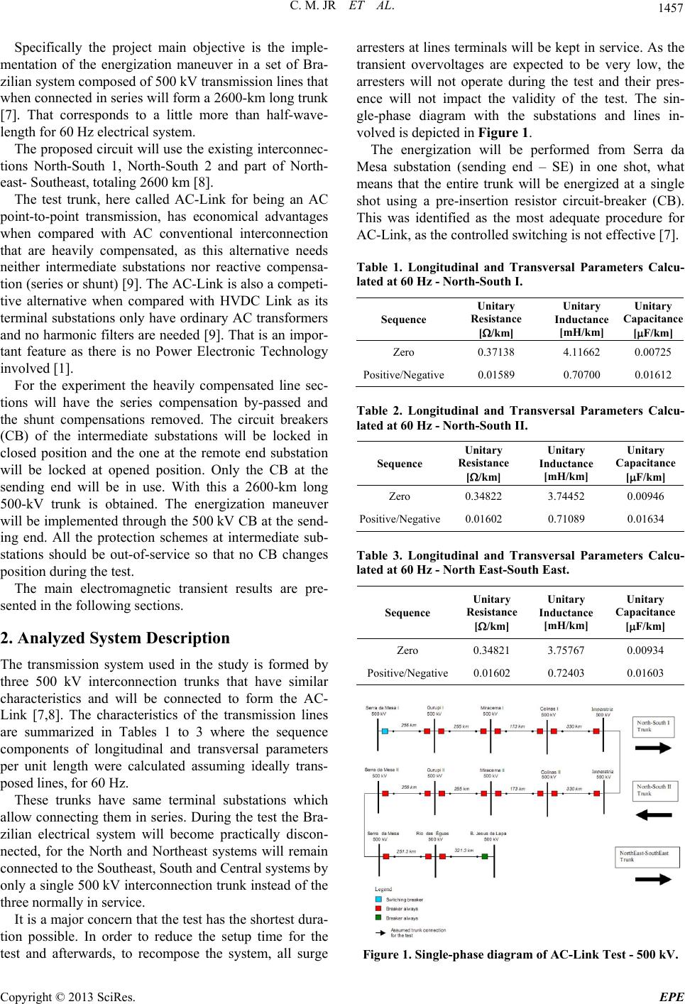 C. M. JR ET AL. 1457 Specifically the project main objective is the imple- mentation of the energization maneuver in a set of Bra- zilian system composed of 500 kV transmission lines that when connected in series will form a 2600-km long trunk [7]. That corresponds to a little more than half-wave- length for 60 Hz electrical system. The proposed circuit will use the existing interconnec- tions North-South 1, North-South 2 and part of North- east- Southeast, totaling 2600 km [8]. The test trunk, here called AC-Link for being an AC point-to-point transmission, has economical advantages when compared with AC conventional interconnection that are heavily compensated, as this alternative needs neither intermediate substations nor reactive compensa- tion (series or shunt) [9]. The AC-Link is also a competi- tive alternative when compared with HVDC Link as its terminal substations only have ordinary AC transformers and no harmonic filters are needed [9]. That is an impor- tant feature as there is no Power Electronic Technology involved [1]. For the experiment the heavily compensated line sec- tions will have the series compensation by-passed and the shunt compensations removed. The circuit breakers (CB) of the intermediate substations will be locked in closed position and the one at the remote end substation will be locked at opened position. Only the CB at the sending end will be in use. With this a 2600-km long 500-kV trunk is obtained. The energization maneuver will be implemented through the 500 kV CB at the send- ing end. All the protection schemes at intermediate sub- stations should be out-of-service so that no CB changes position during the test. The main electromagnetic transient results are pre- sented in the following sections. 2. Analyzed System Description The transmission system used in the study is formed by three 500 kV interconnection trunks that have similar characteristics and will be connected to form the AC- Link [7,8]. The characteristics of the transmission lines are summarized in Tables 1 to 3 where the sequence components of longitudinal and transversal parameters per unit length were calculated assuming ideally trans- posed lines, for 60 Hz. These trunks have same terminal substations which allow connecting them in series. During the test the Bra- zilian electrical system will become practically discon- nected, for the North and Northeast systems will remain connected to the Southeast, South and Central systems by only a single 500 kV interconnection trunk instead of the three normally in service. It is a major concern that the test has the shortest dura- tion possible. In order to reduce the setup time for the test and afterwards, to recompose the system, all surge arresters at lines terminals will be kept in service. As the transient overvoltages are expected to be very low, the arresters will not operate during the test and their pres- ence will not impact the validity of the test. The sin- gle-phase diagram with the substations and lines in- volved is depicted in Figure 1. The energization will be performed from Serra da Mesa substation (sending end – SE) in one shot, what means that the entire trunk will be energized at a single shot using a pre-insertion resistor circuit-breaker (CB). This was identified as the most adequate procedure for AC-Link, as the controlled switching is not effective [7]. Table 1. Longitudinal and Transversal Parameters Calcu- lated at 60 Hz - North-South I. Sequence Unitary Resistance [/km] Unitary Inductance [mH/km] Unitary Capacitance [F/km] Zero 0.37138 4.11662 0.00725 Positive/Negative0.01589 0.70700 0.01612 Table 2. Longitudinal and Transversal Parameters Calcu- lated at 60 Hz - North-South II. Sequence Unitary Resistance [/km] Unitary Inductance [mH/km] Unitary Capacitance [F/km] Zero 0.34822 3.74452 0.00946 Positive/Negative0.01602 0.71089 0.01634 Table 3. Longitudinal and Transversal Parameters Calcu- lated at 60 Hz - North East-South East. Sequence Unitary Resistance [/km] Unitary Inductance [mH/km] Unitary Capacitance [F/km] Zero 0.34821 3.75767 0.00934 Positive/Negative0.01602 0.72403 0.01603 Figure 1. Single-phase diagram of AC-Link Test - 500 kV. Copyright © 2013 SciRes. EPE 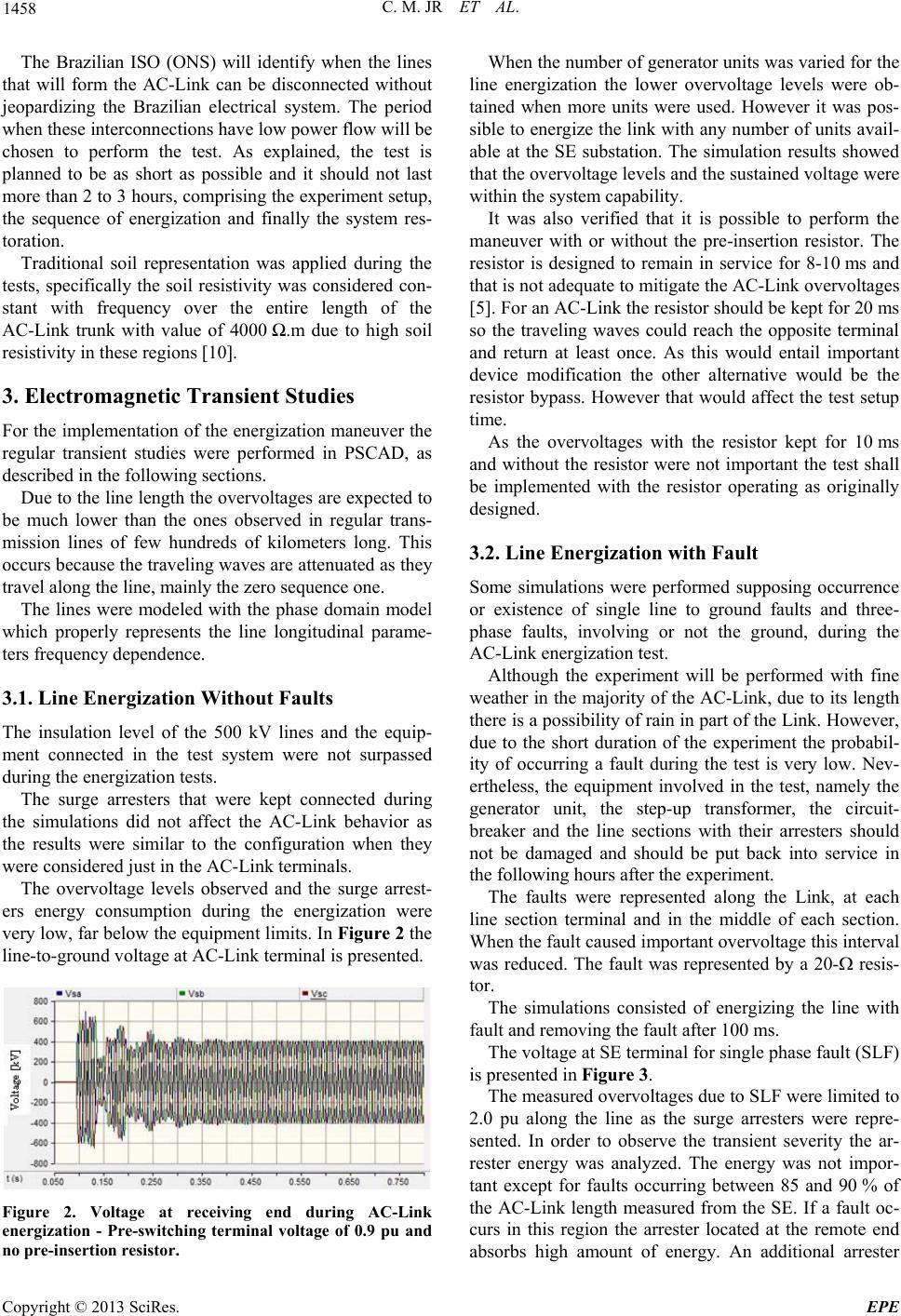 C. M. JR ET AL. 1458 The Brazilian ISO (ONS) will identify when the lines that will form the AC-Link can be disconnected without jeopardizing the Brazilian electrical system. The period when these interconnections have low power flow will be chosen to perform the test. As explained, the test is planned to be as short as possible and it should not last more than 2 to 3 hours, comprising the experiment setup, the sequence of energization and finally the system res- toration. Traditional soil representation was applied during the tests, specifically the soil resistivity was considered con- stant with frequency over the entire length of the AC-Link trunk with value of 4000 Ω.m due to high soil resistivity in these regions [10]. 3. Electromagnetic Transient Studies For the implementation of the energization maneuver the regular transient studies were performed in PSCAD, as described in the following sections. Due to the line length the overvoltages are expected to be much lower than the ones observed in regular trans- mission lines of few hundreds of kilometers long. This occurs because the traveling waves are attenuated as they travel along the line, mainly the zero sequence one. The lines were modeled with the phase domain model which properly represents the line longitudinal parame- ters frequency dependence. 3.1. Line Energization Without Faults The insulation level of the 500 kV lines and the equip- ment connected in the test system were not surpassed during the energization tests. The surge arresters that were kept connected during the simulations did not affect the AC-Link behavior as the results were similar to the configuration when they were considered just in the AC-Link terminals. The overvoltage levels observed and the surge arrest- ers energy consumption during the energization were very low, far below the equipment limits. In Figure 2 the line-to-ground voltage at AC-Link terminal is presented. Figure 2. Voltage at receiving end during AC-Link energization - Pre-switching terminal voltage of 0.9 pu and no pre-insertion resistor. When the number of generator units was varied for the line energization the lower overvoltage levels were ob- tained when more units were used. However it was pos- sible to energize the link with any number of units avail- able at the SE substation. The simulation results showed that the overvoltage levels and the sustained voltage were within the system capability. It was also verified that it is possible to perform the maneuver with or without the pre-insertion resistor. The resistor is designed to remain in service for 8-10 ms and that is not adequate to mitigate the AC-Link overvoltages [5]. For an AC-Link the resistor should be kept for 20 ms so the traveling waves could reach the opposite terminal and return at least once. As this would entail important device modification the other alternative would be the resistor bypass. However that would affect the test setup time. As the overvoltages with the resistor kept for 10 ms and without the resistor were not important the test shall be implemented with the resistor operating as originally designed. 3.2. Line Energization with Fault Some simulations were performed supposing occurrence or existence of single line to ground faults and three- phase faults, involving or not the ground, during the AC-Link energization test. Although the experiment will be performed with fine weather in the majority of the AC-Link, due to its length there is a possibility of rain in part of the Link. However, due to the short duration of the experiment the probabil- ity of occurring a fault during the test is very low. Nev- ertheless, the equipment involved in the test, namely the generator unit, the step-up transformer, the circuit- breaker and the line sections with their arresters should not be damaged and should be put back into service in the following hours after the experiment. The faults were represented along the Link, at each line section terminal and in the middle of each section. When the fault caused important overvoltage this interval was reduced. The fault was represented by a 20- resis- tor. The simulations consisted of energizing the line with fault and removing the fault after 100 ms. The voltage at SE terminal for single phase fault (SLF) is presented in Figure 3. The measured overvoltages due to SLF were limited to 2.0 pu along the line as the surge arresters were repre- sented. In order to observe the transient severity the ar- rester energy was analyzed. The energy was not impor- tant except for faults occurring between 85 and 90 % of the AC-Link length measured from the SE. If a fault oc- curs in this region the arrester located at the remote end absorbs high amount of energy. An additional arrester Copyright © 2013 SciRes. EPE 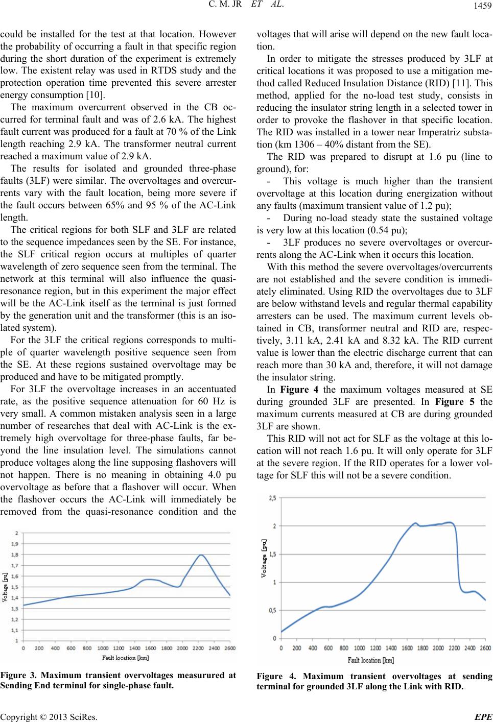 C. M. JR ET AL. 1459 could be installed for the test at that location. However the probability of occurring a fault in that specific region during the short duration of the experiment is extremely low. The existent relay was used in RTDS study and the protection operation time prevented this severe arrester energy consumption [10]. The maximum overcurrent observed in the CB oc- curred for terminal fault and was of 2.6 kA. The highest fault current was produced for a fault at 70 % of the Link length reaching 2.9 kA. The transformer neutral current reached a maximum value of 2.9 kA. The results for isolated and grounded three-phase faults (3LF) were similar. The overvoltages and overcur- rents vary with the fault location, being more severe if the fault occurs between 65% and 95 % of the AC-Link length. The critical regions for both SLF and 3LF are related to the sequence impedances seen by the SE. For instance, the SLF critical region occurs at multiples of quarter wavelength of zero sequence seen from the terminal. The network at this terminal will also influence the quasi- resonance region, but in this experiment the major effect will be the AC-Link itself as the terminal is just formed by the generation unit and the transformer (this is an iso- lated system). For the 3LF the critical regions corresponds to multi- ple of quarter wavelength positive sequence seen from the SE. At these regions sustained overvoltage may be produced and have to be mitigated promptly. For 3LF the overvoltage increases in an accentuated rate, as the positive sequence attenuation for 60 Hz is very small. A common mistaken analysis seen in a large number of researches that deal with AC-Link is the ex- tremely high overvoltage for three-phase faults, far be- yond the line insulation level. The simulations cannot produce voltages along the line supposing flashovers will not happen. There is no meaning in obtaining 4.0 pu overvoltage as before that a flashover will occur. When the flashover occurs the AC-Link will immediately be removed from the quasi-resonance condition and the Figure 3. Maximum transient overvoltages measurured at Sending End terminal for single-phase fault. voltages that will arise will depend on the new fault loca- tion. In order to mitigate the stresses produced by 3LF at critical locations it was proposed to use a mitigation me- thod called Reduced Insulation Distance (RID) [11]. This method, applied for the no-load test study, consists in reducing the insulator string length in a selected tower in order to provoke the flashover in that specific location. The RID was installed in a tower near Imperatriz substa- tion (km 1306 – 40% distant from the SE). The RID was prepared to disrupt at 1.6 pu (line to ground), for: - This voltage is much higher than the transient overvoltage at this location during energization without any faults (maximum transient value of 1.2 pu); - During no-load steady state the sustained voltage is very low at this location (0.54 pu); - 3LF produces no severe overvoltages or overcur- rents along the AC-Link when it occurs this location. With this method the severe overvoltages/overcurrents are not established and the severe condition is immedi- ately eliminated. Using RID the overvoltages due to 3LF are below withstand levels and regular thermal capability arresters can be used. The maximum current levels ob- tained in CB, transformer neutral and RID are, respec- tively, 3.11 kA, 2.41 kA and 8.32 kA. The RID current value is lower than the electric discharge current that can reach more than 30 kA and, therefore, it will not damage the insulator string. In Figure 4 the maximum voltages measured at SE during grounded 3LF are presented. In Figure 5 the maximum currents measured at CB are during grounded 3LF are shown. This RID will not act for SLF as the voltage at this lo- cation will not reach 1.6 pu. It will only operate for 3LF at the severe region. If the RID operates for a lower vol- tage for SLF this will not be a severe condition. Figure 4. Maximum transient overvoltages at sending terminal for grounded 3LF along the Link with RID. Copyright © 2013 SciRes. EPE  C. M. JR ET AL. 1460 3.3. Generator unit Performance During Energization without Fault The AC-Link can be energized from 1, 2 or 3 power units. The requirements of the generators are greater if only one machine is used. However the measured values do not compromise the equipment integrity or reduces its life-time. In Figure 6 the active power is presented for energiza- tion without pre-insertion resistor. 3.4. Generator unit Performance during Energization with Faults Simulations were performed considering the occurrence of faults along the AC-Link during the energization Test. If a single-phase fault occurs the stress will not dam- age the generator unit. Specifically, if a fault occurs in the critical region for SLF the generator will send 1.5 pu of active power and 0.5 pu of reactive power. These val- ues do not affect its unit due to the short duration of this event. In case of three-phase fault, grounded or isolated, the stress again will not damage the generator. Specifically, if a fault occurs in the critical region RID will operate immediately, protecting the generator. During the tran- sient the current in the generator will reach 3.0 pu, re- ducing promptly to 0.7 pu. After the transient the ma- chine injects 0.1 pu active power and 0.60 pu reactive power. 3.5. Line Tripping without Faults The opening of no-load AC-Link results in very low ca- pacitive current and the voltage between the breaker poles is not severe and attenuates very fast, as presented in Figure 7. The results showed that it is possible to open the AC-Link using the existing CB at Serra da Mesa sub- station (SE). The capacitive current through CB poles and the voltage across its terminals are much lower than its capability. Figure 5. Maximum transient current at circuit-breaker for grounded 3LF along the Link with RID. Potência ativa t ( s ) 0.0 1.0 2.0 3.0 4.0 5.0 -0.50 -0.25 0.00 0.25 0.50 0.75 1.00 1.25 1.50 1.75 2.00 PG (pu) PG 1 Figure 6. Active power injected by 1 generator unit during energization without fault – Pre switching voltage: 0.9 pu – Without pre-insertion resistor. Figure 7. TRV of pole A during AC-Link no-load tripping after energization without fault. 3.6. Line Tripping with Faults The simulations consisted of energization and subsequent tripping considering terminal fault, short-line fault and remote fault. The faults analyzed were SLF and 3LF. For remote faults the fault location was varied in order to verify the behavior in critical regions. As there is no standard for such a long trunk tripping, simulations were performed comparing the AC-Link with the line for which the CB was designed for terminal and short-line faults. The actual line is 256 km long with shunt com- pensation in both terminals. It was observed that: - The terminal fault current is similar to the one ob- served for shorter lines even when shunt compensated, as presented in Figure 8; - The short-line-fault for AC-Link is less severe than for similar lines of hundreds of kilometers, as in the latter the inductance of the shunt compensation will produce higher TRV; - The highest current to be interrupted is not defined by terminal fault, but rather by three-phase fault in spe- Copyright © 2013 SciRes. EPE  C. M. JR ET AL. 1461 cific location which varies with the short circuit power (Ssc) of the terminal network. These locations can be from 60 to 85 % of the line length for low and high Ssc, respectively, measured from the circuit breaker; - The voltages at the circuit breaker contacts for re- mote 3LF faults are not severe when RID mitigation procedure is applied; The TRV produced by remote SLF are not severe. 4. Conclusions In the present paper electromagnetic results concerning an energization of an AC-Link trunk formed by existing 500 kV lines are presented. The use of Reduced Insulation Distance (RID) at a tower near Imperatriz substation (1306 km) will mitigate the overvoltages that are produced when a three-phase fault occurs in a specific region (65 to 95 % of Link length measured from SE). This method is adequate for the energization maneuver but is not a straightforward solution to be used during normal operation. With RID the 3LF is not a sever condition for the AC-Link energization. The SLF does not produce high overvoltages, but the energy absorbed by the arresters at the remote end can become excessive if protection does not operate as designed [10]. In that case an additional arrester or a higher thermal capacity arrester may be needed. Regarding the generator units, the requirements for normal operation and operation under faults did not re- sult in special requirements, and the actual machine can cope with the experiment without damaging or reducing its life-time. The actual circuit-breaker designed for a highly shunt compensated 256-km long line was capable of opening Figure 8. TRV across pole A during AC-Link tripping after energization under SLF terminal fault. the no-load AC-Link and also tripping the AC-Link un- der SLF and 3LF (terminal, short-line and remote). Even for the critical region for SLF and 3LF the CB suffered no special stress. It can be stated that the AC-Link energization test can be implemented in the analyzed system without impact- ing the equipment involved (specifically generator unit, transformer, circuit-breaker, line surge arresters and line structure). There will be no damage to the devices in- volved and their life-time will not be reduced due to the stresses imposed by the experiment. The HVAC-Link is a reliable and technically robust solution for very long transmission trunks and due to its constant terminal voltage for all load profile, it should also be carefully analyzed for intermittent power transfer as the ones produced by alternative energy sources, as large solar and wind power plants. In [11, 13] some results regarding line protection are presented. Ongoing research on Single-Phase Auto Re- closing will be presented in a near future. As the AC Link cost is attractive for very long transmission, proper technical solution can be developed if necessary to solve specific needs. 5. Acknowledgements This work was supported CNPq, CAPES and FAPESP in Brazil. The results presented in this paper are partial re- sults from the project supported by ELETROBRAS/ ELETRONORTE, ELETROBRAS/ CHESF and ENTE as part of ANEEL (Brazilian Electrical Energy Regula- tory Agency) strategic project 2008 (proc. 4500072477). The project was coordinated by UNICAMP with the par- ticipation of UFBA and UEFS. REFERENCES [1] C. Portela, J. Silva and M. Alvim, “Non-Conventional AC Solutions Adequate for Very Long Distance Trans- mission-An Alternative for the Amazon Transmission System,” Proceedings of 2007 IEC/CIGRE UHV Sympo- sium Beijing, article 2-2-5, Beijing, China, 2007, p. 29. [2] F. J. Hubert and M. R. Gent, "Half-Wavelength Power Transmission Lines," Power Apparatus and Systems, IEEE Transactions on, Vol. 84, No. 10, 1965, pp. 965-974. doi:10.1109/TPAS.1965.4766125 [3] F. S. PrabhakAra, K. Parthasarathy and H. N. R. Rao, “Analysis of Natural Half-Wave-Length Power Trans- mission Lines,” Power Apparatus and Systems, IEEE Transactions on, Vol. PAS-88, No. 12, 1969, pp. 1787-1794. [4] F. M. Gatta and F. Iliceto, "Analysis of Some Operation Problems of Half-wave Length Power Transmission Lines," AFRICON '92 Proceeding of 3rd AFRICON Con- ference, 22-24 Sep 1992, pp. 59-64. [5] C. Portela, “Some Aspects of Very Long Lines Switching Copyright © 2013 SciRes. EPE  C. M. JR ET AL. Copyright © 2013 SciRes. EPE 1462 - CIGRE SC 13 Colloquium 1995,” Florianópolis, Brazil, 1995, p. 12. [6] J. L. Alqueres and J. C. Praca, "The Brazilian Power Sys- tem and the Challenge of the Amazon Transmission," in Proceedings of 1991 IEEE PES T&D Conference, pp. 315-320. [7] M. C. Tavares and C. M. Portela, “Proposition of a Half-Wave Length Energization Case Test,” International Conference on Power Systems Transients (IPST’09) Kyoto, Japan, IPST 2009. [8] E. C. Gomes and M. C. Tavares, "Analysis of the Energi- zation Test of a Half-Wavelength AC-Link Composed of Similar Transmission Lines," Power and Energy Engi- neering Conference (APPEEC), 2011 Asia-Pacific, 2011, pp. 1-5. [9] Y. Song, B. Fan, Y. Bai, X. Qin and Z. Zhang, "Reliabil- ity and Economic Analysis of UHV Half-Wave-length AC Transmission," Transmission. In Power System Technology (POWERCON), 2012 IEEE International Conference on, New Zealand, Oct. 2012. [10] C. M. Portela, M. C. Tavares, J. P. Filho and J. B.Ger- trudes, “Earth Conductivity and Permittivity Data Meas- urements - Influence in Transmission Line Transient Per- formance,” Electric Power Systems Research, Vol. 76, No. 11, 2006, pp. 907-915. doi:10.1016/j.epsr.2005.11.006 [11] E. C. Gomes, M. C. Tavares and C. Floriano, "Using Conventional Protection for Line-to-ground Fault at AC-Link,” IPST, Vancouver, Canada, 2013. [12] J. B. Gertrudes, E. C. Gomes and M. C. Tavares, “Circuit Breaker TRV on AC-Link Trunk with a Little More than Half-wavelength,” IPST 2013. [13] R. Fabián and M. C. Tavares, “Using of Conventional Relays for Protecting AC-Link from Three-Phase Faults,” IPST 2013. |