

Paper Menu >>
Journal Menu >>
 Energy and Power Engineering, 2013, 5, 1330-1336 doi:10.4236/epe.2013.54B252 Published Online July 2013 (http://www.scirp.org/journal/epe) A Multi-Agent Framework for Operation of a Smart Grid Ruchi Gupta1, Deependra Kumar Jha1, Vinod Kumar Yadav1, Sanjeev Kumar2 1School of Electrical, Communication and Electronics Engineering, Galgotias University, Uttar Pradesh, India 2School of Basic and Applied Sciences, Department of Mathematics, Galgotias University, Uttar Pradesh, India Email: [email protected] Received March, 2013 ABSTRACT This paper presents the operation of a Multi-agent system (MAS) for the control of a smart grid. The proposed Mul- ti-agent system consists of seven types of agents: Single Smart Grid Controller (SGC), Load Agents (LAGs), a Wind Turbine Agent (WTAG), Photo-Voltaic Agents (PVAGs), a Micro-Hydro Turbine Agent (MHTAG), Diesel Agents (DGAGs) and a Battery Agent (BAG). In a smart grid LAGs act as consumers or buyers, WTAG, PVAGs, MHTAG & DGAGs acts as producers or sellers and BAG act as producer/consumer or seller/buyer. The paper demonstrates the use of a Multi-agent system to control the smart grid in a simulated environment. In order to validate the performance of the proposed system, it has been applied to a simple model system with different time zone i.e. day time and night time and when power is available from the grid and when there is power shedding. Simulation results show that the proposed Multi-agent system can perform the operation of the smart grid efficiently. Keywords: Multi-agent System; Smart Grid; Micro-grid; Distributed Generation; Renewable Energy 1. Introduction The security and resiliency of electric power supply to serve critical facilities are of high importance in today’s world. In India, with the increasing complexity of power grids, growing demand and growing concerns for envi- ronment accentuate the leap towards something ‘smarter’. Instead of building large electric power grids and high capacity transmission lines an intelligent approach is essential for transforming the existing power grid to a ‘smarter grid’ widely referred as ‘smart grid’. Smart grid technologies have the potential to transform the existing grids to more efficient, self healing, reliable, safer and less constrained grids [1]. A smart micro-grid can be defined as a low voltage distribution network with distributed energy resource (DER) units, such as the distributed generation (DG) units and distributed storage (DS) units and loads. The DG units utilize Diesel Engines, Micro turbines, Fuel Cells, Photovoltaic (PV) panels, small wind turbines, and com- bined heat and power (CHP) systems. The capacity of the DG sources varies from few kW to 1-2 MW. The DS units could be flywheels, energy capacitors and batteries. The micro-grid can be made smarter by integrating advanced sensing technologies, control methods and communication techniques [1-3]. Smart grids can benefit customers through providing uninterruptible power, en- hancing local reliability, reducing transmission loss, and supporting local voltage and frequency. As the DER units typically operate at a distribution voltage level and geographically close to loads, smart micro-grids are developed to interconnect the energy sources and loads in a relatively small area, such as a suburban community, a university or school, a commer- cial area, and an industrial site. Besides the environ- mental benefit of using more renewable energy sources, a smart grid can either be interconnected to the main grid as a single aggregated load (or generator) or in case of external faults or periods of emergency, it has the capa- bility to separate, or island, from the main grid and oper- ate independently, within limits. Significant research works have been carried out on operation and control of smart grid. Current trends to control and monitor the operation of electrical power systems are however moving towards the use of an automated agent technology, known as multi-agent sys- tem. In recent years, multi-agent based approach is pro- posed/adopted to provide intelligent energy control and management systems in smart grids. Multi-agent systems have become the focus of intense research in European countries [4, 5]. In India, a lot is yet to be done towards making power grids smarter and reliable, capable of taking self correct- ing decisions for optimal scheduling of generation re- sources. In this paper the operation of a multi-agent sys- tem for the control of a smart grid is described in an In- dian scenario. Present power scenario of India is described in Section II. The rest of the paper is organized as follows: Section Copyright © 2013 SciRes. EPE 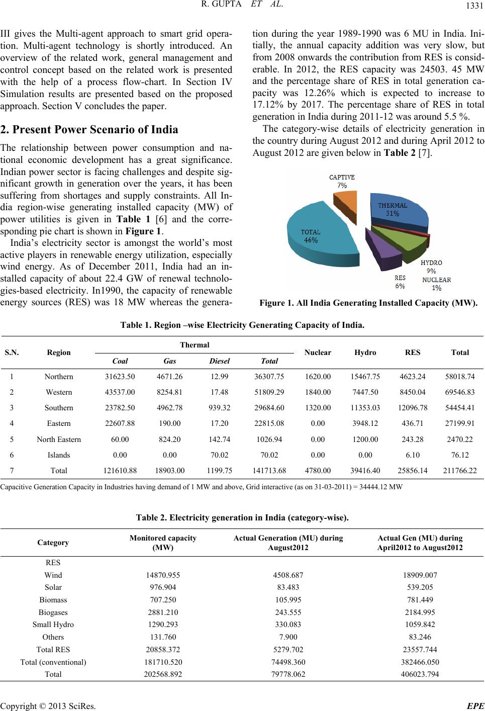 R. GUPTA ET AL. 1331 III gives the Multi-agent approach to smart grid opera- tion. Multi-agent technology is shortly introduced. An overview of the related work, general management and control concept based on the related work is presented with the help of a process flow-chart. In Section IV Simulation results are presented based on the proposed approach. Section V concludes the paper. 2. Present Power Scenario of India The relationship between power consumption and na- tional economic development has a great significance. Indian power sector is facing challenges and despite sig- nificant growth in generation over the years, it has been suffering from shortages and supply constraints. All In- dia region-wise generating installed capacity (MW) of power utilities is given in Table 1 [6] and the corre- sponding pie chart is shown in Figure 1. India’s electricity sector is amongst the world’s most active players in renewable energy utilization, especially wind energy. As of December 2011, India had an in- stalled capacity of about 22.4 GW of renewal technolo- gies-based electricity. In1990, the capacity of renewable energy sources (RES) was 18 MW whereas the genera- tion during the year 1989-1990 was 6 MU in India. Ini- tially, the annual capacity addition was very slow, but from 2008 onwards the contribution from RES is consid- erable. In 2012, the RES capacity was 24503. 45 MW and the percentage share of RES in total generation ca- pacity was 12.26% which is expected to increase to 17.12% by 2017. The percentage share of RES in total generation in India during 2011-12 was around 5.5 %. The category-wise details of electricity generation in the country during August 2012 and during April 2012 to August 2012 are given below in Table 2 [7]. Figure 1. All India Generating Installed Capacity (MW). Table 1. Region –wise Electricity Generating Capacity of India. Thermal S.N. Region Coal Gas Diesel Total Nuclear Hydro RES Total 1 Northern 31623.50 4671.26 12.99 36307.75 1620.00 15467.75 4623.24 58018.74 2 Western 43537.00 8254.81 17.48 51809.29 1840.00 7447.50 8450.04 69546.83 3 Southern 23782.50 4962.78 939.32 29684.60 1320.00 11353.03 12096.78 54454.41 4 Eastern 22607.88 190.00 17.20 22815.08 0.00 3948.12 436.71 27199.91 5 North Eastern 60.00 824.20 142.74 1026.94 0.00 1200.00 243.28 2470.22 6 Islands 0.00 0.00 70.02 70.02 0.00 0.00 6.10 76.12 7 Total 121610.88 18903.00 1199.75 141713.68 4780.00 39416.40 25856.14 211766.22 Capacitive Generation Capacity in Industries having demand of 1 MW and above, Grid interactive (as on 31-03-2011) = 34444.12 MW Table 2. Electricity generation in India (category-wise). Category Monitored capacity (MW) Actual Generation (MU) during August2012 Actual Gen (MU) during April2012 to August201 2 RES Wind 14870.955 4508.687 18909.007 Solar 976.904 83.483 539.205 Biomass 707.250 105.995 781.449 Biogases 2881.210 243.555 2184.995 Small Hydro 1290.293 330.083 1059.842 Others 131.760 7.900 83.246 Total RES 20858.372 5279.702 23557.744 Total (conventional) 181710.520 74498.360 382466.050 Total 202568.892 79778.062 406023.794 Copyright © 2013 SciRes. EPE  R. GUPTA ET AL. 1332 3. Multi-Agent Based Operation of Smart Grid 3.1. Multi-Agent System A multi-agent system is a combination of several agents working in collaboration pursuing assigned tasks to achieve the overall goal of the system. The multi-agent system has become an increasingly powerful tool in de- veloping complex systems that take advantages of agent properties: autonomy, sociality, reactivity and pro-activ- ity. The multi-agent system is social-able in that they interact with other agents via some kind of agent com- munication language. The agents also perceive and react to their environment. Lastly, the multi-agent system is proactive in that they are able to exhibit goal-oriented behavior by taking initiatives [1-4, 8-12]. In the context of power systems, multi-agent technolo- gies can be applied in a variety of applications, such as to perform power system disturbance diagnosis, power sys- tem restoration, power system secondary voltage control and power system visualization. Some of the recent re- searchers have implemented multi-agent system to con- trol the operation of a smart grid. 3.2. Agent Model of the Proposed Smart Grid The proposed model of the smart grid consists of several agents that communicate and coordinate with each other. The smart grid model that is used in the proposed appli- cation is simple, since we focus mainly on the coopera- tion of agents. Figure 2 shows the architecture of the smart grid. Smart grid is connected to the main grid. The Smart Grid Controller announces the time zone (day/ night) and availability of grid. The production units that belong to the smart grid adjust their set points based on their availability, the time zone, availability of the grid, grid price, their operational cost and the load demand [1]. a) Load Agent (LAG) LAG is installed at each load centre. Main functions of LAG are: i. Load Forecasting: LAG makes a prediction about the demand of next day. The forecast demand for electricity is determined from the historical data and the weather forecast for tomorrow. ii. Sending Message: LAG sends a request message to SGC for the power purchase. The message includes the amount of power and its price. iii. Receiving Message: LAG receives from SGC a message that tells from where to purchase the elec- tric power. b) Battery Agent (BAG) BAG, installed at each battery centre, has attributes such as the amount of charge, the capacity and the status (charge/discharge). The following describes the main functions of BAG. i. Measurement of the state of charge: BAG conducts to measure the amount of battery charge. Battery is charged when Grid is available and discharged when Grid is not available. ii. Sending Message: BAG sends a request message to SGC for the power purchase or sale. The message includes the amount of power and its price. iii. Receiving Message: BAG receives from SGC a message that tells when to purchase or sale the elec- tric power. c) Smart-Grid-Controller (SGC) SGC, a special purpose agent facilitates the negotia- tion process of the multi-agent system. The following describes the main functions of the SGC. i. Controlling the timing of the negotiation: SGC sug- gests the timing of the negotiation by sending a message to open the market to all agents in the smart grid. ii. Decision making of the operation: SGC makes a decision of the operation of producer or pro- ducer/consumer agents. d) Wind Turbine Agent (WTAG) WTAG, installed at each wind turbine generator, has attributes such as the generator available power. The fol- lowing describes the main functions of WTAG. i. Sending Message: WTAG sends a request message to SGC for the power sale. The message includes the amount of power and its price. ii. Receiving Message: WTAG receives from SGC a message that tells where to sale the electric power. e) Photo-Voltaic Agent (PVAG) PVAG, installed at each photo-voltaic generator, has attributes such as the generator available power. The fol- lowing describes the main functions of PVAG. i. Sending Message: PVAG sends a request message to SGC for the power sale. The message includes availability, the amount of power and its price. ii. Receiving Message: PVAG receives from SGC a message that tells where to sale the electric power. f) Micro-Hydro Turbine Agent (MHTAG) Figure 2. Agent model of the proposed smart grid Copyright © 2013 SciRes. EPE  R. GUPTA ET AL. 1333 MHTAG, installed at each micro-hydro turbine gen- erator, has attributes such as the generator available power. The following describes the main functions of MHTAG. i. Sending Message: MHTAG sends to SGC a mes- sage to request for the power sale. The message in- cludes the amount of power and its price. ii. Receiving Message: MHTAG receives from SGC a message that tells where to sale the electric power. g) Diesel Generator Agent (DGAG) DGAG, installed at each diesel generator, has attrib- utes such as the generator minimum/maximum output value. The following describes the main functions of DGAG. i. Sending Message: DGAG sends to SGC a message to request for the power sale. The message includes the amount of power and its price. ii. Receiving Message: DGAG receives from SGC a message that tells where and when to sale the elec- tric power. h) Steps for Sorting Process The sorting algorithm (flow chart as shown in Figure 3) for available generating resources (producers) is explained as below: Step 1: Collect the following data of the available sources/ producers: (i) Power cost per unit (ii) Availability of the producer (iii) Power availability with the producer Assign ID in numeric to the producer(s). Step 2: (i) Sort the array of producers in the order of price (ii) The producers which are available and can give power at that time slot are sorted in ascending order of cost/price. Step3: Read the Demand (Load). Step 4: Identify the producers which can fulfill the demand using the array sorted in Step 2, individually or in combination. Step 5: Send the producer ID and capacity to SGC. i) Negotiation Process Negotiation is one of the key processes for the multi- agent system to successfully attain its goal. Flow-chart in Figure 4 shows the negotiation process. There are seven types of agents in the proposed system viz. SGC, LAG, BAG, PVAG, WTAG, MHTAG and DGAG. The main objective is to fulfill the demand (load) at a particular time by minimizing the use of diesel genera- tors as their per unit price outreach other available sources. To accomplish this, the agents are required to cooperate and coordinate so that they make efficient use of the power supplied by other sources at the time of power shedding. Figure 3. Flow-chart for sorting of producers (Generating units) for SGC SGC is informed about the demand, producer avail- ability and the operating cost per unit of different pro- ducers in one negotiation cycle. At the time of power shedding, if the electrical power in the smart grid is in- sufficient, demand is fulfilled by the diesel generators. SGC sends a message of announcement of tender to all agents in the smart grid every 10 minutes. SGC is sug- gested to control the timing of the negotiation process. All buyer agents in the smart grid reply a message of purchase of electrical power. The message includes the amount of electrical power i.e. Demand ‘D’. All producer agents in the smart grid reply a message of sale of elec- trical power. The message includes the generator avail- able power, their availability at a particular time and their operating cost per unit. In the next step, sorting of producers and the grid is done depending upon their availability and operating costs in ascending order of price per unit. This sorted list is then sent to the SGC that makes a decision on opera- tion of different producers based on this generated list. The demand is checked with the power available with the producer. If the demand is not fulfilled by first pro- ducer, SGC sends operation command to next producer and so on until the demand is fulfilled. Finally, genera- tion load pattern is displayed for a given time period and next negotiation cycle begins. Copyright © 2013 SciRes. EPE 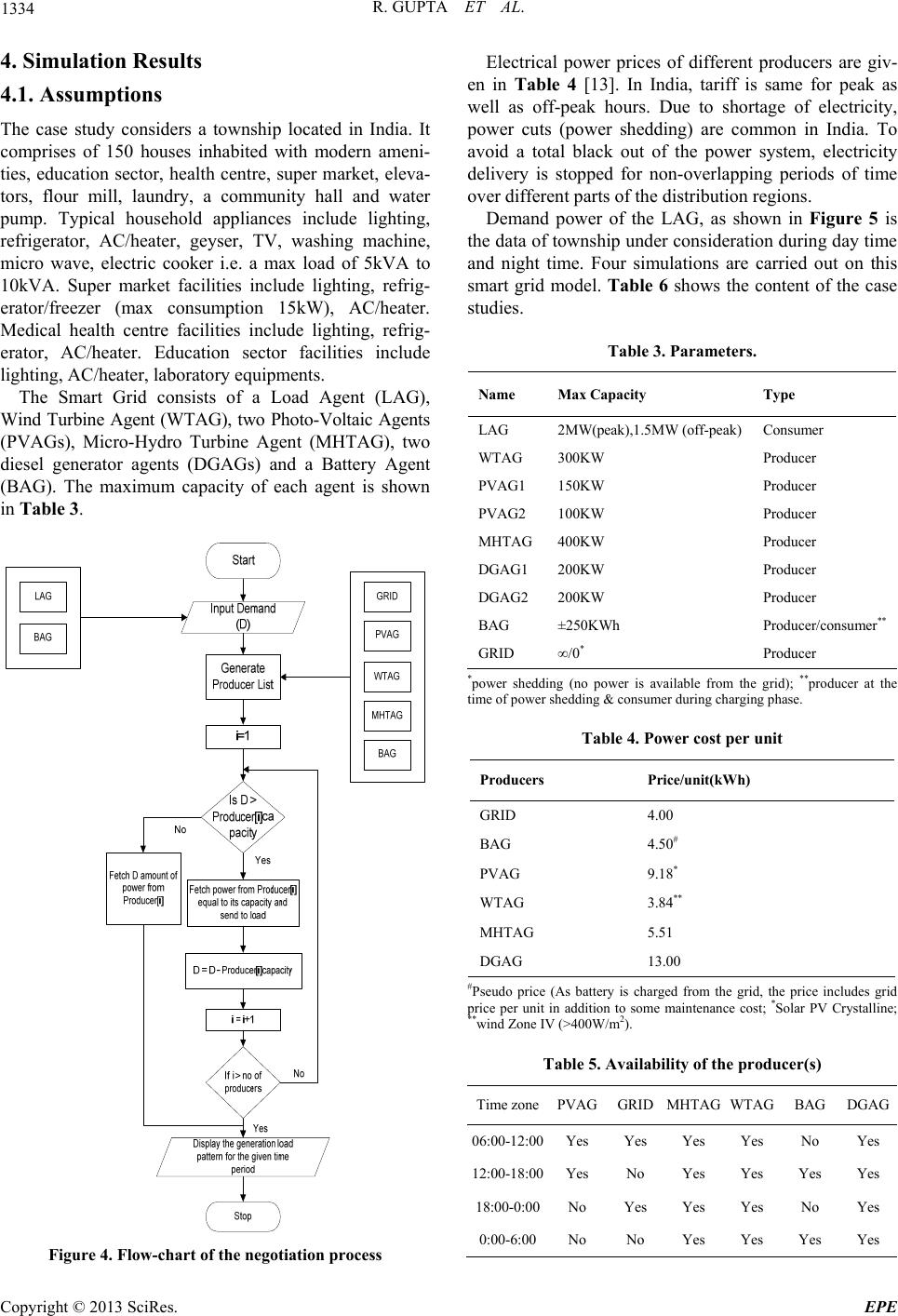 R. GUPTA ET AL. 1334 4. Simulation Results 4.1. Assumptions The case study considers a township located in India. It comprises of 150 houses inhabited with modern ameni- ties, education sector, health centre, super market, eleva- tors, flour mill, laundry, a community hall and water pump. Typical household appliances include lighting, refrigerator, AC/heater, geyser, TV, washing machine, micro wave, electric cooker i.e. a max load of 5kVA to 10kVA. Super market facilities include lighting, refrig- erator/freezer (max consumption 15kW), AC/heater. Medical health centre facilities include lighting, refrig- erator, AC/heater. Education sector facilities include lighting, AC/heater, laboratory equipments. The Smart Grid consists of a Load Agent (LAG), Wind Turbine Agent (WTAG), two Photo-Voltaic Agents (PVAGs), Micro-Hydro Turbine Agent (MHTAG), two diesel generator agents (DGAGs) and a Battery Agent (BAG). The maximum capacity of each agent is shown in Table 3. Figure 4. Flow-chart of the negotiation process Electrical power prices of different producers are giv- en in Table 4 [13]. In India, tariff is same for peak as well as off-peak hours. Due to shortage of electricity, power cuts (power shedding) are common in India. To avoid a total black out of the power system, electricity delivery is stopped for non-overlapping periods of time over different parts of the distribution regions. Demand power of the LAG, as shown in Figure 5 is the data of township under consideration during day time and night time. Four simulations are carried out on this smart grid model. Table 6 shows the content of the case studies. Table 3. Parameters. Name Max Capacity Type LAG 2MW(peak),1.5MW (off-peak) Consumer WTAG 300KW Producer PVAG1 150KW Producer PVAG2 100KW Producer MHTAG 400KW Producer DGAG1 200KW Producer DGAG2 200KW Producer BAG ±250KWh Producer/consumer** GRID ∞/0* Producer *power shedding (no power is available from the grid); **producer at the time of power shedding & consumer during charging phase. Table 4. Power cost per unit Producers Price/unit(kWh) GRID 4.00 BAG 4.50# PVAG 9.18* WTAG 3.84** MHTAG 5.51 DGAG 13.00 #Pseudo price (As battery is charged from the grid, the price includes grid price per unit in addition to some maintenance cost; *Solar PV Crystalline; **wind Zone IV (>400W/m2). Table 5. Availability of the producer(s) Time zonePVAGGRIDMHTAG WTAG BAGDGAG 06:00-12:00Yes Yes Yes Yes No Yes 12:00-18:00Yes No Yes Yes Yes Yes 18:00-0:00No Yes Yes Yes No Yes 0:00-6:00No No Yes Yes Yes Yes Copyright © 2013 SciRes. EPE 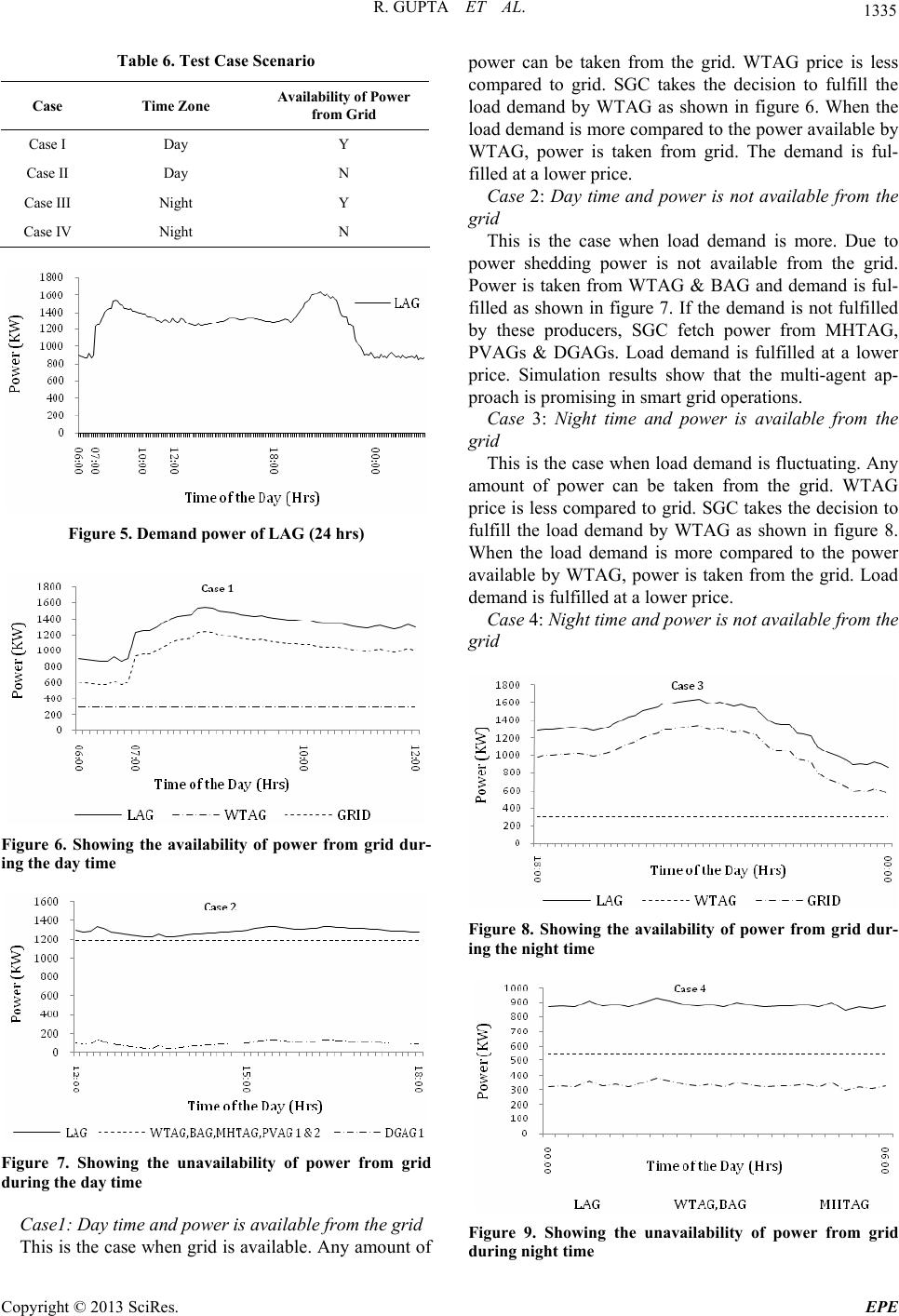 R. GUPTA ET AL. 1335 Table 6. Test Case Scenario Case Time Zone Availability of Power from Grid Case I Day Y Case II Day N Case III Night Y Case IV Night N Figure 5. Demand power of LAG (24 hrs) Figure 6. Showing the availability of power from grid dur- ing the day time Figure 7. Showing the unavailability of power from grid during the day time Case1: Day time and power is available from the grid This is the case when grid is available. Any amount of power can be taken from the grid. WTAG price is less compared to grid. SGC takes the decision to fulfill the load demand by WTAG as shown in figure 6. When the load demand is more compared to the power available by WTAG, power is taken from grid. The demand is ful- filled at a lower price. Case 2: Day time and power is not available from the grid This is the case when load demand is more. Due to power shedding power is not available from the grid. Power is taken from WTAG & BAG and demand is ful- filled as shown in figure 7. If the demand is not fulfilled by these producers, SGC fetch power from MHTAG, PVAGs & DGAGs. Load demand is fulfilled at a lower price. Simulation results show that the multi-agent ap- proach is promising in smart grid operations. Case 3: Night time and power is available from the grid This is the case when load demand is fluctuating. Any amount of power can be taken from the grid. WTAG price is less compared to grid. SGC takes the decision to fulfill the load demand by WTAG as shown in figure 8. When the load demand is more compared to the power available by WTAG, power is taken from the grid. Load demand is fulfilled at a lower price. Case 4: Night time and power is not available from the grid Figure 8. Showing the availability of power from grid dur- ing the night time Figure 9. Showing the unavailability of power from grid during night time Copyright © 2013 SciRes. EPE  R. GUPTA ET AL. Copyright © 2013 SciRes. EPE 1336 This is the case when load demand is less. Due to power shedding power is not available from the grid. Power is taken from WTAG and BAG and demand is fulfilled as shown in figure 9. If the demand is not ful- filled by these producers SGC fetch power from MHTAG and then from DGAG. Load demand is fulfilled at a lower price. Simulation results show that the mul- ti-agent approach is promising in smart grid operation. 5. Conclusions This paper presents the benefits of multi-agent system for smart grid operation. This is achieved effectively through the negotiation skills and coordination of actions between SGC and various agents. The proposed approach is vali- dated in a simulated environment that considers both the availability and outage conditions of the power grid. Based on the method, the algorithm and various test case scenarios, it is found that the proposed multi-agent ap- proach is viable in smart grid operations. REFERENCES [1] T. Nagata, Y. Ueda and M. Utatani, “A Multi-agent Ap- proach to Smart Grid Operations,” The 2012 IEEE Con- ference on Power System Technology (POWERCON), 2012, pp. 1-5. doi:10.1109/PowerCon.2012.6401303 [2] M. Pipattanasomporn, H. Feroze and S. Rahman, “Mul- ti-Agent Systems in a Distributed Smart Grid: Design and Implementation,” Proceedings of IEEE PES 2009 Power Systems Conference and Exposition (PSCE’09), Mar 2009, Seattle, Washington, USA. [3] J. J. Lu, X. Da and A. Qian, “Research on Smart Grid in China,” Proceedings of Transmission & Distribution Conference & Exposition: Asia and Pacific, 2009, pp. 1-4. [4] A. L. Dimeas and N. D. Hatziargyriou, “Operation of a Multi-agent System for Microgrid Control,” IEEE Transactions on Power systems, Vol. 20, No. 3, 2005, pp. 1447-1455. doi:10.1109/TPWRS.2005.852060 [5] A. L. Dimeas and N. D. Hatziargyriou, “Agent based control of Virtual Power Plants,” IEEE The 14th Interna- tional Conference on Intelligent System Applications to Power Systems, ISAP 2007 November 4 - 8, 2007, Kaoh- siung, Taiwan 536. [6] Available online at: http://www.cea.nic.in/reports/monthly/executive_rep/jan1 3/8.pdf [7] Available online at: www.cea.nic.in/reports/articles/god/renewable_energy.pd f. [8] A. Dimeas and N. D. Hatziagyriou, “A Multi-agent Sys- tem for Micro Grids,” In Proc. IEEE PES General Meet- ing, Denver, CO, Jun. 2004, PESGM2004–001, p. 244. [9] A. L. Dimeas, S. I. Hatzivasiliadis and N. D. Hatziargy- riou, “Control Agents for Enabling Customer-driven Mi- cro Grids,” Proceedings of Power & Energy Society General Meeting, 2009. PES '09. IEEE, 26-30 July 2009, pp. 1-7. [10] A. L. Dimeas and N. D. Hatziargyriou, “Agent Based Control for Microgrids,” Proceedings of IEEE PES Gen- eral Meeting, Tampa, FL, June 24-28, 2007 [11] S. J. Chatzivasiliadis, N. D. Hatziargyriou and A. L. Di- meas, “Development of an Agent Based Intelligent Con- trol System for Micro Grids,” The 2008 IEEE Power and Energy Society General Meeting on Conversion and De- livery of Electrical Energy in the 21st Century, 20-24 July, 2008, pp. 1-6. [12] A. L. Dimeas and N. D. Hatziargyriou, “A MAS archi- tecture for Micro grids Control,” Proceedings of the 13th International Conference on Intelligent Systems Applica- tion to Power Systems, 6-10 Nov, 2005. doi:10.1109/ISAP.2005.1599297 [13] Available online at: http://mnre.gov.in/filemanager/UserFiles/september_mon th_2012_rerf.pdf. |