

Paper Menu >>
Journal Menu >>
 Energy and Power Engineering, 2013, 5, 1317-1323 doi:10.4236/epe.2013.54B250 Published Online July 2013 (http://www.scirp.org/journal/epe) Review of Modeling Methods of Distributed Energy Supply System Connected to the Grid Shengxuan Wei, Qianjin Liu School of Electric Power, South China University of Technology, Guangzhou, China Email: [email protected] Received March, 2013 ABSTRACT At present, the development of distribution network can’t meet the requirements of rapid economic development. The traditional single energy supply is difficult to meet the request, and distributed energy supply has a lot of advantages compared to it, particularly it's close to the end users, and they have been developed well and applied widely in recent years. This paper summarizes the features and current development of the distributed energy supply, and mainly describes the grid-connection model of distributed energy supply. Base on the mathematic grid-connection model of distributed power sources with different generation principles as well as that energy storage, the treatment of these models in distribution network power flow analysis is also presented. Keywords: Modeling; Distributed Energy Supply; Grid-connection 1. Introduction Recently, centralized power generation, long-distance transmission and grid interconn ection constitute th e main way of electricity production, transmission and distribution. Long-distance transmission has its advantages, but there are also some drawbacks, including: Cannot agilely tracking load changes, local accident easy to expand to a major accident. In addition, centralized power generation consume a large number of fossil fuels, produce large amounts of greenhouse gases and substances harmful to the environment. For the purpose of environmental protection, it is necessary to use more wind, solar and other renewable energy. Therefore, the interest in using renewable energy and small/medium-sized generators are increasing, especially in the increasingly rapid development of wind power and photovoltaic power generation. A lot of research and practice in this area have been done. At the same time, the new technology of using conventional fossil fuels, fuel cells and microturbines is also object of the study. They can reduce the emission of pollutants greatly. Most experts agree that combination of large power grid and distributed power generation, together with the appropriate energy storage equipment, so as to save investment, reduce energy consumption, improve power system reliability and flexibility, and are the keys to the development of the electric power industry. After the penetration of distributed energy systems, the characteristics of single-power and radial will change. 2. Research Status of Distributed Power and Energy Storage Battery Currently, the exact definition of distributed power supply is not recognized. The common definition is that generated power from 1 kW to 50 MW of small independent power module. They are typically installed near the user, in order to meet the specific needs of the user or to support the economic operation of the existing distribution netw ork [1]. At present, the widely use of distributed power supply system mainly contain wind power, photovoltaic cells, fuel cells, micro turbines and storage batteries. The distribution network is generally designed to radiate, user side does not have any power supply. Penetration of distributed power makes the network have more than one power supply node. This will create difficulties for the operation of the power grid, will seriously affect the distribution network power flow, increase short-circuit current of the power distribution network, and make voltage regulation beco mes difficult. In order to improve the power quality and operational reliability, its install location and capacity must be optimized. Thus, in order to apply to the distributed power access, the original method of power flow calculation applied to traditional radial distribution network planning and optimization must be improved [2]. [3] Proposed an object-oriented modeling method and a reconfiguration algorithm for radial distribution network which take into account the distributed power Copyright © 2013 SciRes. EPE 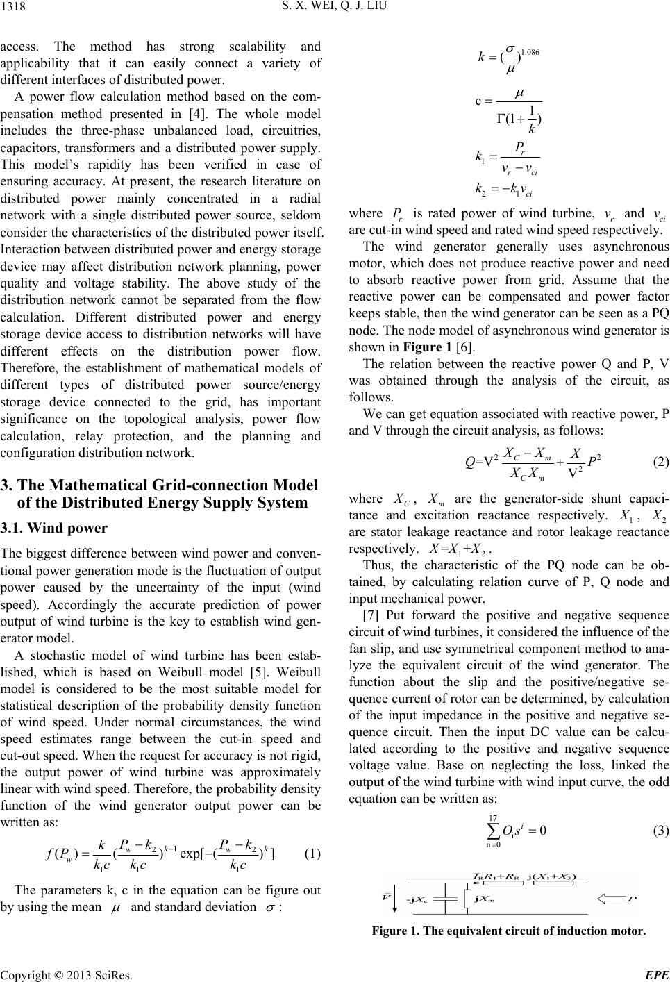 S. X. WEI, Q. J. LIU 1318 access. The method has strong scalability and applicability that it can easily connect a variety of different interfaces of distributed power. A power flow calculation method based on the com- pensation method presented in [4]. The whole model includes the three-phase unbalanced load, circuitries, capacitors, transformers and a distributed power supply. This model’s rapidity has been verified in case of ensuring accuracy. At present, the research literature on distributed power mainly concentrated in a radial network with a single distributed power source, seldom consider the characteristics of the distributed power itself. Interaction between distributed power and energy storage device may affect distribution network planning, power quality and voltage stability. The above study of the distribution network cannot be separated from the flow calculation. Different distributed power and energy storage device access to distribution networks will have different effects on the distribution power flow. Therefore, the establishment of mathematical models of different types of distributed power source/energy storage device connected to the grid, has important significance on the topological analysis, power flow calculation, relay protection, and the planning and configuration distribution network. 3. The Mathematical Grid-connection Model of the Distributed Energy Supply System 3.1. Wind power The biggest difference between wind power and conven- tional power generation mode is the fluctuation of output power caused by the uncertainty of the input (wind speed). Accordingly the accurate prediction of power output of wind turbine is the key to establish wind gen- erator model. A stochastic model of wind turbine has been estab- lished, which is based on Weibull model [5]. Weibull model is considered to be the most suitable model for statistical description of the probability density function of wind speed. Under normal circumstances, the wind speed estimates range between the cut-in speed and cut-out speed. When the request for accuracy is not rigid, the output power of wind turbine was approximately linear with wind sp eed. Th er efore, th e probab ility den sity function of the wind generator output power can be written as: 1 22 11 1 ()()exp[() kk ww w Pk Pk k fP kc kckc ] (1) The parameters k, c in the equation can be figure out by using the mean and standard deviation : 1.086 ()k 1 21 c1 (1 ) r rci ci k P kvv kkv where r is rated power of wind turbine, r and ci are cut-in wind speed and rated wind speed respectively. Pv v The wind generator generally uses asynchronous motor, which does not produce reactive power and need to absorb reactive power from grid. Assume that the reactive power can be compensated and power factor keeps stable, then the wind generator can be seen as a PQ node. The node mode l of asynchronous wi nd generator is shown in Figure 1 [6]. The relation between the reactive power Q and P, V was obtained through the analysis of the circuit, as follows. We can get equation associated with reactive power, P and V through the circuit analysis, as follows: 22 2 =V V Cm Cm XX X QP XX (2) where C X , m X are the generator-side shunt capaci- tance and excitation reactance respectively. 1 X , 2 X are stator leakage reactance and rotor leakage reactance respectively. 12 =+ X XX. Thus, the characteristic of the PQ node can be ob- tained, by calculating relation curve of P, Q node and input mechanical power. [7] Put forward the positive and negative sequence circuit of wind turbines, it consid ered the influence of th e fan slip, and use symmetrical component method to ana- lyze the equivalent circuit of the wind generator. The function about the slip and the positive/negative se- quence current of rotor can be determined, by calculation of the input impedance in the positive and negative se- quence circuit. Then the input DC value can be calcu- lated according to the positive and negative sequence voltage value. Base on neglecting the loss, linked the output of the wind turbine with wind input curve, the odd equation can be written as: 17 i n0 0 i Os (3) Figure 1. The equivalent circuit of induction motor. Copyright © 2013 SciRes. EPE 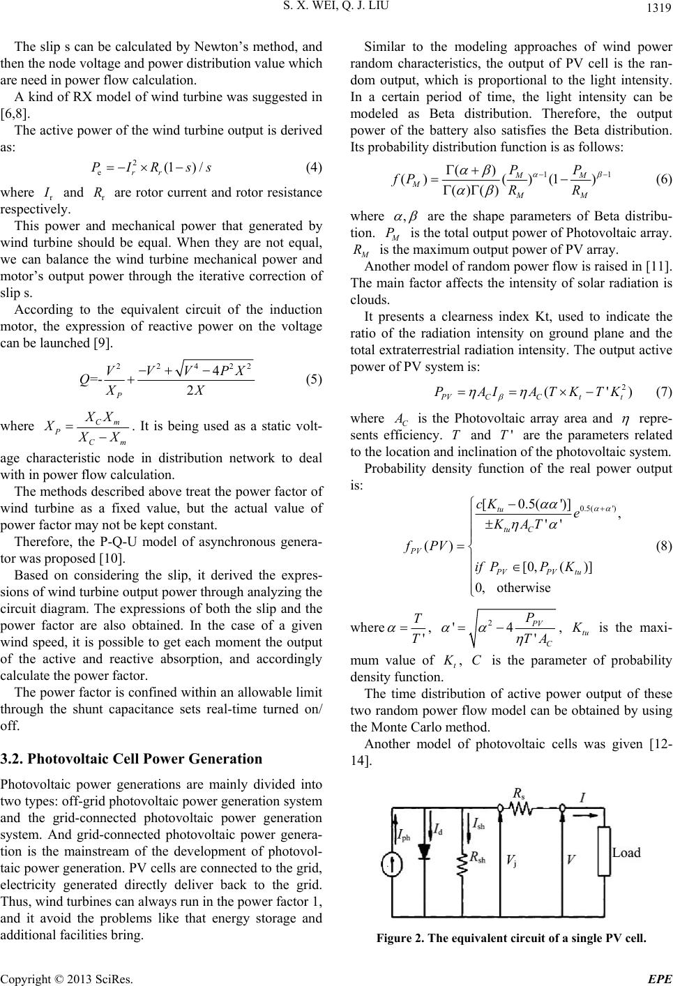 S. X. WEI, Q. J. LIU 1319 The slip s can be calculated by Newton’s method, and then the node voltage and power distribution value which are need in power flow calculation. A kind of RX model of wind turbine was suggested in [6,8]. The active power of the wind turbine outpu t is derived as: 2 e(1) / rr PIRs s (4) where r I and are rotor current and rotor resistance respectively. r R This power and mechanical power that generated by wind turbine should be equal. When they are not equal, we can balance the wind turbine mechanical power and motor’s output power through the iterative correction of slip s. According to the equivalent circuit of the induction motor, the expression of reactive power on the voltage can be launched [9]. 2242 4 =- 2 P VVVPX QXX 2 (5) where Cm PCm XX X X X . It is being used as a static volt- age characteristic node in distribution network to deal with in power flow calculation. The methods described above treat the power factor of wind turbine as a fixed value, but the actual value of power factor may not be kept constant. Therefore, the P-Q-U model of asynchronous genera- tor was proposed [10]. Based on considering the slip, it derived the expres- sions of wind turb ine ou tput power through an alyzing the circuit diagram. The expressions of both the slip and the power factor are also obtained. In the case of a given wind speed, it is possible to get each moment the output of the active and reactive absorption, and accordingly calculate the power factor. The power factor is confined within an allowable limit through the shunt capacitance sets real-time turned on/ off. 3.2. Photovoltaic Cell Power Generation Photovoltaic power generations are mainly divided into two types: off-grid photovoltaic power generation system and the grid-connected photovoltaic power generation system. And grid-connected photovoltaic power genera- tion is the mainstream of the development of photovol- taic power generation. PV cells are connected to the grid, electricity generated directly deliver back to the grid. Thus, wind turbines can always run in the power factor 1, and it avoid the problems like that energy storage and additional facilities bring. Similar to the modeling approaches of wind power random characteristics, the output of PV cell is the ran- dom output, which is proportional to the light intensity. In a certain period of time, the light intensity can be modeled as Beta distribution. Therefore, the output power of the battery also satisfies the Beta distribution. Its probability distribution function is as follows: 1 () ()( )(1) ()() MM MMM PP fP RR 1 (6) where , are the shape parameters of Beta distribu- tion. M P is the total output power of Photovoltaic array. M R is the maximum output power of PV array. Another model of random power flow is raised in [11]. The main factor affects the intensity of solar radiation is clouds. It presents a clearness index Kt, used to indicate the ratio of the radiation intensity on ground plane and the total extraterrestrial radiation intens ity. The output active power of PV sy st em is: 2 (') P VCC tt PAIATKTK (7) where C A is the Photovoltaic array area and repre- sents efficiency. and are the parameters related to the location and inclination of th e photovoltaic system. T'T Probability density function of the real power output is: 0.5( ') [0.5(')], '' () [0,( )] 0, otherwise tu tu C PV PVPV tu cK e KAT fPV if PPK (8) where ' T T , 2 '4 ' PV C P TA , tu K is the maxi- mum value of t K , is the parameter of probability density function. C The time distribution of active power output of these two random power flow model can be obtained by using the Monte Carlo method. Another model of photovoltaic cells was given [12- 14]. Figure 2. The equivalent circuit of a single PV cell. Copyright © 2013 SciRes. EPE 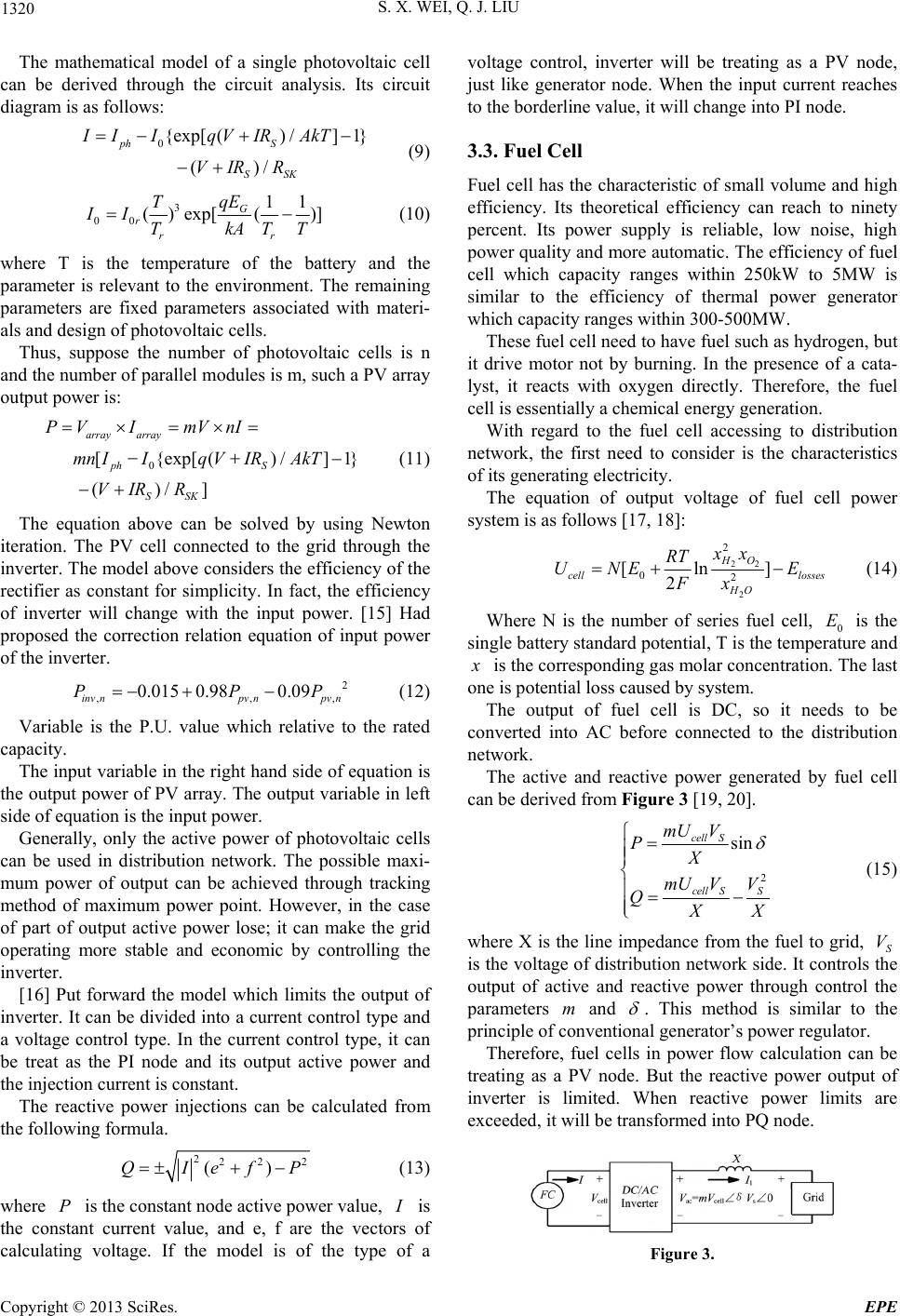 S. X. WEI, Q. J. LIU 1320 The mathematical model of a single photovoltaic cell can be derived through the circuit analysis. Its circuit diagram is as follows: 0{exp[() /]1} ()/ ph S SSK IIIqVIR AkT VIR R (9) 3 00 11 ()exp[()] G rrr qE T II TkAT T , P (10) where T is the temperature of the battery and the parameter is relevant to the environment. The remaining parameters are fixed parameters associated with materi- als and design of photovoltaic cells. Thus, suppose the number of photovoltaic cells is n and the number of parallel modules is m, such a PV array output power is: 0 [{exp[()/]1} ()/] array array ph S SSK PV ImVnI mn IIq VIRAkT VIR R (11) The equation above can be solved by using Newton iteration. The PV cell connected to the grid through the inverter. The model above considers the efficiency of the rectifier as constant for simplicity. In fact, the efficiency of inverter will change with the input power. [15] Had proposed the correction relation equation of input power of the inverter. 2 ,, 0.015 0.980.09 inv npv npv n PP (12) Variable is the P.U. value which relative to the rated capacity. The input variable in th e right hand side of equation is the output power of PV array. The output variable in left side of equation is the input power. Generally, only the active power of photovoltaic cells can be used in distribution network. The possible maxi- mum power of output can be achieved through tracking method of maximum power point. However, in the case of part of output active power lose; it can make the grid operating more stable and economic by controlling the inverter. [16] Put forward the model which limits the output of inverter. It can be divided into a current control type and a voltage control type. In the current control type, it can be treat as the PI node and its output active power and the injection curren t is constant. The reactive power injections can be calculated from the following formula. 222 2 ()QIefP (13) where is the constant node active power value, P I is the constant current value, and e, f are the vectors of calculating voltage. If the model is of the type of a voltage control, inverter will be treating as a PV node, just like generator node. When the input current reaches to the borderline value, it will change into PI node. 3.3. Fuel Cell Fuel cell has the characteristic of small volume and high efficiency. Its theoretical efficiency can reach to ninety percent. Its power supply is reliable, low noise, high power quality and more automatic. The efficiency of fuel cell which capacity ranges within 250kW to 5MW is similar to the efficiency of thermal power generator which capacity rang es within 300-500MW. These fuel cell need to have fuel such as hydrogen, but it drive motor not by burning. In the presence of a cata- lyst, it reacts with oxygen directly. Therefore, the fuel cell is essentially a chemical energy generation. With regard to the fuel cell accessing to distribution network, the first need to consider is the characteristics of its generating electricity. The equation of output voltage of fuel cell power system is as follows [17, 18]: 22 2 2 02 [ln] 2 HO cell losses HO xx RT UNE E Fx (14) Where N is the number of series fuel cell, 0 is the single battery standard potential, T is the temperature and E x is the corr espo nding g a s mo lar concen tratio n. Th e last one is potential loss caused by system. The output of fuel cell is DC, so it needs to be converted into AC before connected to the distribution network. The active and reactive power generated by fuel cell can be deri ved from Figure 3 [19, 20]. 2 sin cell S cell SS mU V PX mU VV Q X X (15) where X is the line impedance from the fuel to grid, S is the voltage of distribution network side. It controls the output of active and reactive power through control the parameters and V m . This method is similar to the principle of conventiona l generator’s power r egulator. Therefore, fuel cells in power flow calculation can be treating as a PV node. But the reactive power output of inverter is limited. When reactive power limits are exceeded, it will be transformed into PQ node. Figure 3. Copyright © 2013 SciRes. EPE  S. X. WEI, Q. J. LIU 1321 3.4. Micro Gas Turb nary synchronous generator. and excitation system. ine Gas turbine works like ordi It has a speed control system The speed control system adjusts active power output according to load level. 1 [1.3 eN P ( 0.23)] 2 f W (16) where into electric p g is the efficiency of turbine mecha ower, the fuel ratio required for no-load nical power operatin is 0.23, f W is fuel flow, N is rotational speed. Microturbine combines th e traditional gas turb ine with the recuperator, panent magnet generator, variable erm fr ower frequency current before import to di equency regulation technique and intelligent control technology. The current generated by microturbine need to transform to p stribution network. Whereas, just like centralized generators, its active power can still be adj usted: , () tt fi i t i VV QV , t fi X (17) ,, 1 1 R m inm outR ww PP g Rw (18) where is the engine power, t i V, t f i X is the motor outputr, and are tinput and output powe of ,min ,mout power engine respectively, w PP he and R w are the angular velocity of the sen end and receiving end of power units, M and R are the torqe and imdance of generator respectively Excitation device and power electronic device keep the output voltage of gas t ding u pe urbine stable. For this reason, gas tu atical Model of Energy Storage Device Distributed Access grid of unthe di Battery model is the most studied storage way. Its unit ow. [21] Put forward with a model rbine generator can be treating as a PV node. For the voltage deviation appear in process of iterative algorithm, the reactive power can be adjusted by sensitivity matrix. In the iterative process, the node type converts between PV node and PQ node once the reactive power or voltage exceeds the limit. 4. The Mathem Both wind power and solar cell h ave the characteristic stable power output. Energy storing device store unstable energy and release energy according to demand. Sometime power in grid is insufficient, and is surplus in other times. If the energy storage devices connect to stribution network, it will play an effective ro le in load staggering management. At present, the most common type of distributed energy storage is storage battery. 4.1. Battery Model energy storage cost is l of battery cell access to distribution network. The current of battery itself is DC. Hence, it need the converter' help to access to grid. The active and reactive power through inverter and grid is as follow: sin SR UU PX (c os) RRS U QU U X (19) where X is impedance, and are t voltage of Distribution rk anorage battery of nd The charge/discharge process of battery is divided into oat arge battery if it detect that battery nt violent reaction affect the ode to 80 percent. After this, it S U netwo U d sthe output respectively. The exchange active a reactive power between battery and grid can be adjusted through controlling the phase shift and the output amplitude of inverter. 4.2. The Charge/Discharge Process of Battery three stages: main charge mode (constant current), fl charge mode (limitary-voltage) and even charge mode (constant voltage). 4.2.1. Main Charge Mo de The system will ch lack of electricity. To preve battery life, it uses constant current charging mode. The current rating is commonly 0.1C. Where, C is the capacity of battery pack. The battery can b e topped up in 10 hours if it has been charging in this way. For constant current charge, the voltage of battery pack will continue to rise. When it rises to no minal v oltage o f sin gle b attery, float charge mode will displace main charge mode. 4.2.2. Even Charge Mode Experiments show that charging in constant current m need eight hours to get back adopts to even charge mode automatically. The limit voltage is 24n, where n represent the number of a pack. This process takes almost 10 hours, and the charging current reduces gradually. When the current is 0.01 C, the battery is fully charge. At this point, the float charge mode begins. Figure 4. Copyright © 2013 SciRes. EPE 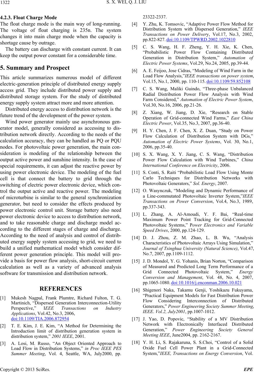 S. X. WEI, Q. J. LIU 1322 4.2.3. Float Charge Mo d e The float charge mode is the main way of long-running The voltage of float charging is 235n. The system changes it into main charge mode when the capacity is shortage cause by outrage. The battery can discharge with constant current. It can keep the output power constant for a considerable time. 5. Summary and P merous model of different more and more attention. se asynchronous gen- d as accessing to . rospect This article summarizes nu electric-generation principle of distributed energy supply access grid. They include distributed power supply and distributed storage system. For the study of distributed energy supply system attract Distributed energy access to distribution network is the future trend of the development of the power system. Wind power generator mainly u erator model, generally considere dis- tribution network directly. According to the needs of the calculation accuracy, they can be handled as PQ or PQU nodes. For photovoltaic power generation, the main con- sideration is modeling of the relationship between the output active power and sunshine intensity. In the case of special requirements, it can adjust the reactive power by using power electronic device. The modeling of the fuel cell is that connect the battery to grid through the switching of electric power electronic device, which con- trol the output active and reactive power. The modeling of microturbine is similar to the general synchronization generator, but need to consider the effects produced by power electronic control unit. Storage battery also need power electronic device to access to distribution network, and to take reasonable charge and discharge model ac- cording to the different stages of charge and discharge. According to the need of analysis and control of distrib- uted energy supply system accessing to grid, we need to build a unified mathematical model which consider dif- ferent power generation principle. This model will pro- vide a basis for power flow analysis, short-circuit current calculation as well as a variety of advanced analysis software for transmission and distribution network. REFERENCES [1] Mukesh Nagpal, Frank Plumtre, Richard Fulton, T. G. Martinich, “Dispersed Generation Interconnection-Utility Perspective,” IEEE Transactions on Industry Applications, Vol.42, No.3, 2006, doi:10.1109/TIA.2006.872954 [2] T. E. Kim, J. E. Kim, “A Method for Determining the Introduction limit of distribution generation system in distribution system,” 2001 IEEE, 2001. [3] A. Losi, M. Ru Load Flow inin Proc IEEE P Summer Meeting, Vol. 4, Seattle, WA, July2000, pp , Vol.17, No.3, 2002, D.2002.1022810 sso, “An Object Oriented Approach to Distribution Systems,” ES . 23322-2337. [4] Y. Zhu, K. Tomsovic, “Adaptive Power Flow Method for Distribution System with Dispersed Generation,” IEEE Transactions on Power Delivery pp.822-827. doi:10.1109/TPWR Automation of [5] C. S. Wang, H. F. Zheng, Y. H. Xie, K. Chen, “Probabilistic Power Flow Containing Distributed Generation in Distribution System,” Electric Power Systems, Vol.29, No.24, 2005, pp.39-44. [6] A. E. Feijoo, Jose Cidras, “Modeling of Wind Farm in the Load Flow Analysis,”IEEE transactions on power system, Vol.15, No.1, 2000, pp. 110-115. doi:10.1109/59.852108 [7] C. S. Wang, Maliki Guindo, “Three-phase Unbalanced Radial Distribution Power Flow Analysis with Wind Farm Considered,” Automation of Electric Power System, Vol.30, No.16, 2006, pp.21-26. [8] Z. Xiang, W. Jiang, D. Xie, “Research on Stable Operation of Grid-connected Wind Farms,” East China Electric Power, Vol.35, No.3, 2007, pp.36-40. [9] H. Y. Chen, J. F. Chen, X. Z. Duan, “Study on Power Flow Calculation of Distribution System with DGs,” Automation of Electric Power Systems, Vol. 30, No.1, 2006, pp.35-40. [10] S. X. Wang, X. Y. Jiang, C. S. Wang, “Distribution Power Flow Calculation with Wind Turbines,” China International Conference on Electricity, 2006. [11] S. Conti, S. Raiti “Probabilistic Load Flow Using Monte Carlo Techniques for Distribution Networks with Photovoltaic Generators,” Sol. Energy, 2007. [12] O. Wasynczuk, “Modeling and Dynamic Performance of a Line-commutated Photovoltaic Inverter System,”IEEE Transactions on Power Conversion, Vol.4, No.3, 1989, pp.337-343. [13] L. Zhang, A. Al-Amoudi, Y. F. Bai, “Real-time Maximum Power Point Tracking for Grid-Connected Photovoltaic Systems,” Power Electronics and Variable Speed Drives, 2000, pp.124-129. [14] D. J. Zhou, Z. M. Zhao, L. B. Wu, “Analysis Characteristics of Photovoltaic Arrays Using Simulation,” Journal of Tsinghua University (Natural Science), Vol.47, No.7, 2007, pp.1109-1112. [15] J. D. Mondol, Y. G. Yohanis, Brian Norton, “Comparison of Measured and Predicted Long Term Performance of a Grid Connected Photovoltaic System,” Energy Conversion and Management, Vol. 48, No. 4, 2007, pp.1065-1080. doi:10.1016/j.enconman.2006.10.021 [16] Shigenori Naka, Takamu Genji, Yoshikazu Fukuyama, “Practical Equipment Models for Fast Distribution Power Flow Considering Interconnection of Distributed Generators,” Power Engineering Society Summer Meeting, IEEE. Vol. 2, July200 1, pp.1007-1012. [17] J. Yao, D. Popovic, “Stability of a MV Distribution Network with Electronically Interfaced Distributed Generation,” Power Engineering Society General Meeting IEEE, June2004, pp. 2162-2167. [18] Y. H. Li, S. Rajakaruna, S. S.Choi, “Control of a Solid Oxide Fuel Cell Power Plant in a Grid-Connected Sys te m, ”IEEE, Transactions on Energy Conversion, Vol. Copyright © 2013 SciRes. EPE  S. X. WEI, Q. J. LIU Copyright © 2013 SciRes. EPE 1323 22, No. 2, 2007, pp.405-413. doi:10.1109/TEC.2005.853756 [19] M. Y. El-Sharkh, A. Rahman, M. S.Alam, “Analysis of Activeand Reactive Power Control of a Stand-Alone PEM Fuel Cell Power Plant,” IEEE Transactions on Power Systems, Vol.19, No. 4, 2004, pp. 2022-2028. [20] Rekha, T. Jagaduri, Ghadir Radman, “Modeling and control of distributed generation systems including PEM fuel cell and gas turbine,” Electric Power System Research, Vol. 77, No.1, 2007, pp.83-92. doi:10.1016/j.epsr.2006.02.003 [21] J. Zeng, B. H. Zhang, C. X. Mao, et al., “Use of Battery Energy Storage to Improve the Power Quality and Stability of Wind Farms,” International Conference on Power System Technology, pp.1-6. |