

Paper Menu >>
Journal Menu >>
 Energy and Power Engineering, 2013, 5, 1209-1214 doi:10.4236/epe.2013.54B229 Published Online July 2013 (http://www.scirp.org/journal/epe) PCHD-Based Passivity Control of VSC-HVDC Connected Large Wind Farm Xinming Fan1, Lin Guan1, Chengjun Xia1, He Jianming1, Xiaolin Li2, Shukai Xu2 1School of Electric Power, South China University of Technology, Guangzhou, China 2Electric Power Research Institute, CSG, Guangzhou, China Email: [email protected] Received March, 2013 ABSTRACT Concentrated integration of large scale wind power demands stronger robustness of VSC-HVDC transmission. Based on PCHD (Port Controled Hamiltonian with Dissipation) equation, the PCHD model of voltage source converter (VSC) in abc frame and d-q rotating frame are built and the strict passivity of VSC is proved. Desired energy function is con- structed and used as Lyapunov function by assigning link matrix and damping matrix. Impact from VSC equivalent dc resistance is eliminated by additional d amping matrix. The IDA-PB (Interconnection and Damping Assignment Passiv- ity-based) controller is designed based on desired equilibrium point and state variable. With different operation condi- tions, VSC-HVDC and its control system are simulated by software PSCAD/EMTDC, the results show the proposed control strategy has good performance and strong robustness. Keywords: VSC-HVDC; Passivity; PCHD System; Damping Assignment; IDA-PB Control 1. Introduction The use of wind power is a keystone in the policy of every country for its renewable energy development goals. Meanwhile wind farm is large-scalely developed and the capacity of a single wind farm increases to hun- dreds or thousands of MW [1]. HVDC with voltage source converter (VSC-HVDC) has fine dynamic char- acteristic and transmission flexibility, furthermore it im- proves the stability of power system [2,3]. In addition, VSC-HVDC is more economical for hundred megawatts wind farm connection [4]. Therefore, VSC-HVDC has obvious techno-economic advantages for the connection of large scale wind farm. The VSC-HVDC system can be operated in three modes: 1) constant dc voltage control mode; 2) constant active and reactive power control mode; and 3) constant ac voltage control mode[5]. And one of converters has to control the dc voltage to make power balanced and the dc voltage stable[6]. However four control inputs of the VSC-HVDC and their interac- tion make it a truly nonlinear multiple-input and multi- ple-output system. Furthermore the fluctuation of wind power will cause deviation of the electric variable in connection point. So VSC-HVDC need strong robustness to deliver power. At present, voltage vector oriented double closed loop PID control[7] based on synchronously rotating frame and direct power control are commonly used. But they both have weak robustness and it is difficult to tune PID parameters. To eliminate the impacts of nonlinearity of VSC-HVDC and improve its robustness, many research works have been carried out, including feedback lineari- zation and sliding mode control[5], adaptive back-stepping control in Ref.[8], fuzzy PI control in Ref.[9] and neural ne twork PID in Ref. [10 ]. Bu t it is still difficult to achieve ideal effects because of the multi- variable structure and highly coupled nonlinearity of the VSC-HVDC system. Passivity control is an emerging nonlinear control the- ory based on the energy dissipation of system[11,12]. Its profound physics meaning has significant relation with Lyapunov function. IDA-PB control is a passivity control based on PCHD. This paper, IDA-PB control strategy is proposed based on the PCHD model of VSC-HVDC. The control decreases dependence of system parameters and makes VSC-HVDC connected large wind power has smaller static error and stronger robustness. The simula- tion results show its advantages. 2. Topology and Model of the VSC-HVDC The single line diagram of the VSC-HVDC connected a wind farm is shown in Figure 1. The detailed structure of VSC is shown in Figure 2, the transformer reactance and power loss are equivalent to L and R, and the parameters of the three phase circuits Copyright © 2013 SciRes. EPE 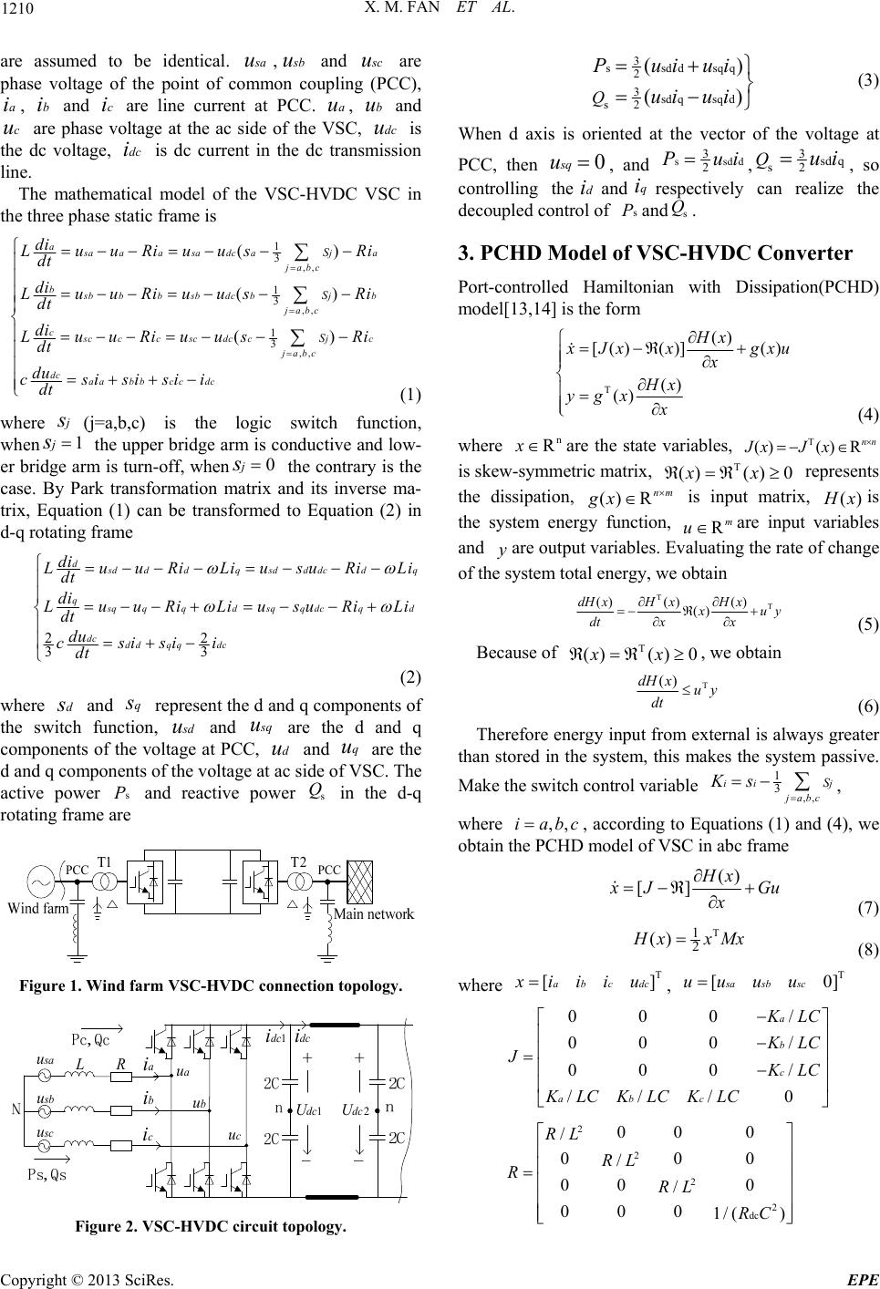 X. M. FAN ET AL. 1210 are assumed to be identical. s au, s bu and s cu bu dcu are phase voltage of the point of common coupling (PCC), , and are line current at PCC. , and are phase voltage at the ac side of the VSC, is the dc voltage, is dc current in the dc transmission line. ai cubiciau dci The mathematical model of the VSC-HVDC VSC in the three phase static frame is ,, ,, ,, 1 3 1 3 1 3 () () () a s aaa sadcaja j abc b s bbb sbdcbjb j abc c s ccc scdccjc j abc dc aabbcc dc S S S di LuuRiuusR dt di LuuRiuus R dt di LuuRiuus Ri dt du csisisii dt i i (1) where (j=a,b,c) is the logic switch function, when the upper bridge arm is conductive and low- er bridge arm is turn-off, when the contrary is the case. By Park transformation matrix and its inverse ma- trix, Equation (1) can be transformed to Equation (2) in d-q rotating fram e js1js0 js 22 33 d s dddq sdddcd q q s qqq dsqqdcqd dc dd qqdc di LuuRiLiusuRiL dt di LuuRiLiusuRiL dt du csisii dt i i (2) where and represent the d and q components of the switch function, dsqs s du and s quu are the d and q components of the voltage at PCC, and are the d and q components of the voltage at ac side of VSC. The active power and reactive power in the d-q rotating frame are dq u sPs Q T1 T2 PCC PCC Figure 1. Wind farm VSC-HVDC connection topology. a i b i ci dc i s a u R L 1dc U 2dc U 1dc i s b u s c u a u b u c u Figure 2. VSC-HVDC circuit topology. 3 ssddsqq 2 3sd qsq d s2 () () Q P ui ui ui ui (3) When d axis is oriented at the vector of the voltage at PCC, then 0squ , and ssddi 3 2 Pu,3sd q s2 Qui, so controlling theand respectively can realize the decoupled control of and. diqi sPs Q 3. PCHD Model of VSC-HVDC Converter Port-controlled Hamiltonian with Dissipation(PCHD) model[13,14] is the form T () [() ()]() () () Hx x Jx xgxu x Hx ygxx (4) where are the state variables, n RxT ()() R nn JxJ x T() 0xx rep is skew-symmetric matrix, (resents the dissipation, () Rgx ) nm t matrix, () is inpu H xis stem energy function, Rm uare input variables and yare outp variables. Evaluating the rate of change of the system total energy, we obtain the sy ut TT () () () () dH xHxH x x uy dt xx (5) Because of T ()() 0xx , we obtain T ()dH xuy dt (6) Therefo re energy input fr om external is always greater than stored in the system, this makes the system passive. Make the switch control variable ,, 1 3 ii jabc SKs j , where ,,i abc , according to Equations (1) and (4), we obtain the PCHD model of VSC in abc frame () [] Hx x JG x u (7) T 1 2 () H xxMx ] (8) where , T []abc dcxiiiuT [0sa sb scuuuu 000 / 000/ 000/ /// 0 a b c abc KLC KLC JKLC KLCKLCKLC 2 2 2 2 dc 00 0 / 00 / 00 0 / 000 1/( ) RL RL RRL RC 0 Copyright © 2013 SciRes. EPE 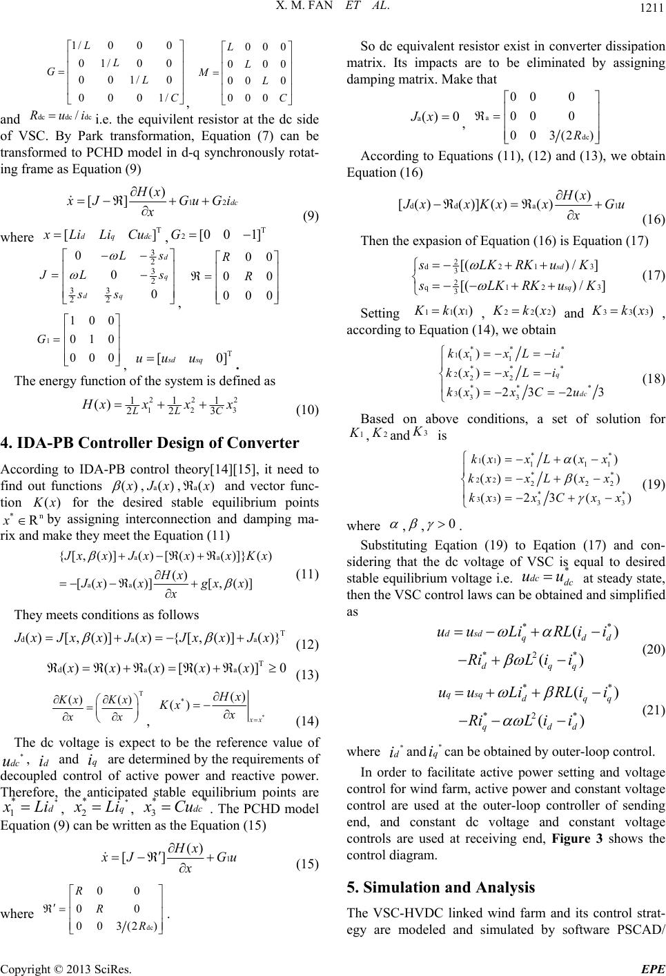 X. M. FAN ET AL. 1211 , 1/0 0 0 01/00 001/0 0001/ L L GL C 000 000 00 0 000 L L ML C and dcdc dc/ R uii.e. the equivilent resistor at the dc side of VSC. By Park transformation, Equation (7) can be transformed to PCHD model in d-q synchronously rotat- ing frame as Equation (9) 12 () [] dc Hx x JGu x Gi (9) where , T []dq dcxLiLiCuT 2[0 01]G 3 0Ls 2 3 2 33 22 0 0 d q dq J Ls ss ] , 00 00 000 R R 1 100 010 000 G , . T [0sdsquu u The energy function of the system is defined as 22 12 111 223 () LLC 2 3 H xxxx (10) 4. IDA-PB Controller Design of Converter According to IDA-PB control theory[14][15], it need to find out functions () x ,a() J x,a() x and vector func- tion () K x n R for the desired stable equilibrium points by assigning interconnection and damping ma- rix and make they meet the Equation (11) * x aa aa {[,( )]()[( )( )]}() () [()()][,()] J xxJxxxKx Hx Jxxgxx x (11) They meets conditions as follows T da ()[,()] (){[,()] ()} a J xJxxJx JxxJx (12) T da a ()() ()[() ()]0xx xx x (13) T () ()Kx Kx xx , * *() () x x Hx Kx x (14) The dc voltage is expect to be the reference value of , and are determined by the requirements of decoupled control of active power and reactive power. Therefore, the anticipated stable equilibrium points are * dcu * 1 di * d qi x Li, * q * 2 x Li, * 3dc* x Cu. The PCHD model Equation (9) can be written as th e Equation (15) 1 () [] Hx x J x Gu (15) where dc 00 00 003(2) R R R . So dc equivalent resistor exist in converter dissipation matrix. Its impacts are to be eliminated by assigning damping matrix. Make that a() 0Jx, a dc 00 0 00 0 003(2 )R According to Equations (11), (12) and (13), we obtain Equation (16) dd a () [()()] ()()Hx1 J xxKxx G x u (16) Then the expasion of Equation (16) is Equation (17) 2 d21 3 2 q12 3 [() /] [() /] sd sq sLKRKuK 3 3 s LK RKuK (17) Setting 111() K kx ,222() K kxand 333() K kx , according to Equation (14), we obtain ** * 111 ** * 222 ** * 333 () () ()2 323 d q dc kxxLi kxxLi kxx Cu (18) Based on above conditions, a set of solution for 1 K ,2 K and 3 K is ** 11 111 ** 22 222 ** 33 33 ()( ) ()() ()2 3() kxx Lxx kxxLx x kxxCx x 3 (19) where , ,0 . Substituting Eqation (19) to Eqation (17) and con- sidering that the dc voltage of VSC is equal to desired stable equilibrium voltage i.e. at steady state, then the VSC con trol laws can be obtained and simplified as * dc dc uu ** *2* () () dsd qd dqq uuLiRLii RiL ii d (20) ** *2* () () qsqdq qdd uuLiRLii RiL ii q (21) where and can be obtai n ed by outer-loop c o ntrol. * di* qi In order to facilitate active power setting and voltage control for wind farm, active power and constant voltage control are used at the outer-loop controller of sending end, and constant dc voltage and constant voltage controls are used at receiving end, Figure 3 shows the control diagram. 5. Simulation and Analysis The VSC-HVDC linked wind farm and its control strat- egy are modeled and simulated by software PSCAD/ Copyright © 2013 SciRes. EPE 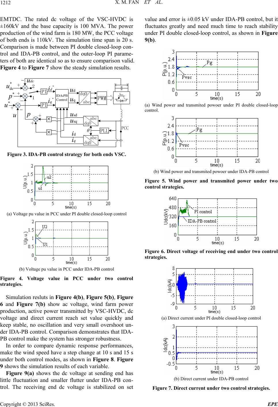 X. M. FAN ET AL. 1212 EMTDC. The rated dc voltage of the VSC-HVDC is ±160kV and the base capacity is 100 MVA. The power production of the wind farm is 180 MW, the PCC voltage of both ends is 110kV. The simulation time span is 20 s. Comparison is made between PI double closed-loop con- trol and IDA-PB control, and the outer-loop PI parame- ters of both are identical so as to ensure co mpariso n valid. Figure 4 to Figure 7 show the steady simulation results. d u d i q i q u * di * q i sd u sq u * p * u p u * dc u dc u Figure 3. IDA-PB control strategy for both ends VSC. (a) Voltage pu value in P CC under PI double clo sed-loop control (b) Voltage pu value in PCC under IDA-PB conl Figure control Simulation resluts in Figure 4(b), Figure 5(b), Figure 6 ces, m nd has litt tro 4. Voltage value in PCC under two strategies. and Figure 7(b) show ac voltage, wind farm power production, active power transmitted by VSC-HVDC, dc voltage and direct current reach set value quickly and keep stable, no oscillation and very small overshoot un- der IDA-PB control. Comparison demonstrates that IDA- PB control make the system has stronger robustness. In order to compare dynamic response performan ake the wind speed have a step change at 10 s and 15 s under both control modes, as shown in Figure 8. Figure 9 shows the simulation results of each variable. Figure 9(a) shows the dc voltage at sending e le fluctuation and smaller flutter under IDA-PB con- trol. The receiving end dc voltage is stabilized on set value and error is ±0.05 kV under IDA-PB control, but it fluctuates greatly and need much time to reach stability under PI double closed-loop control, as shown in Figure 9(b). (a) Wind power and transmited powoer under PI double closed-loop control. (b) Wind power and transmited powoer under IDA-PB control Figwo ure 5. Wind power and transmited power under t control strategies. Figure 6. Direct voltage of receiving end under twcontrol o strategies. (a) Direct curren t under PI double closed-loop conol tr (b) Direct c urrent under IDA-PB control Figure 7.rategies. Direct current under two control st C opyright © 2013 SciRes. EPE 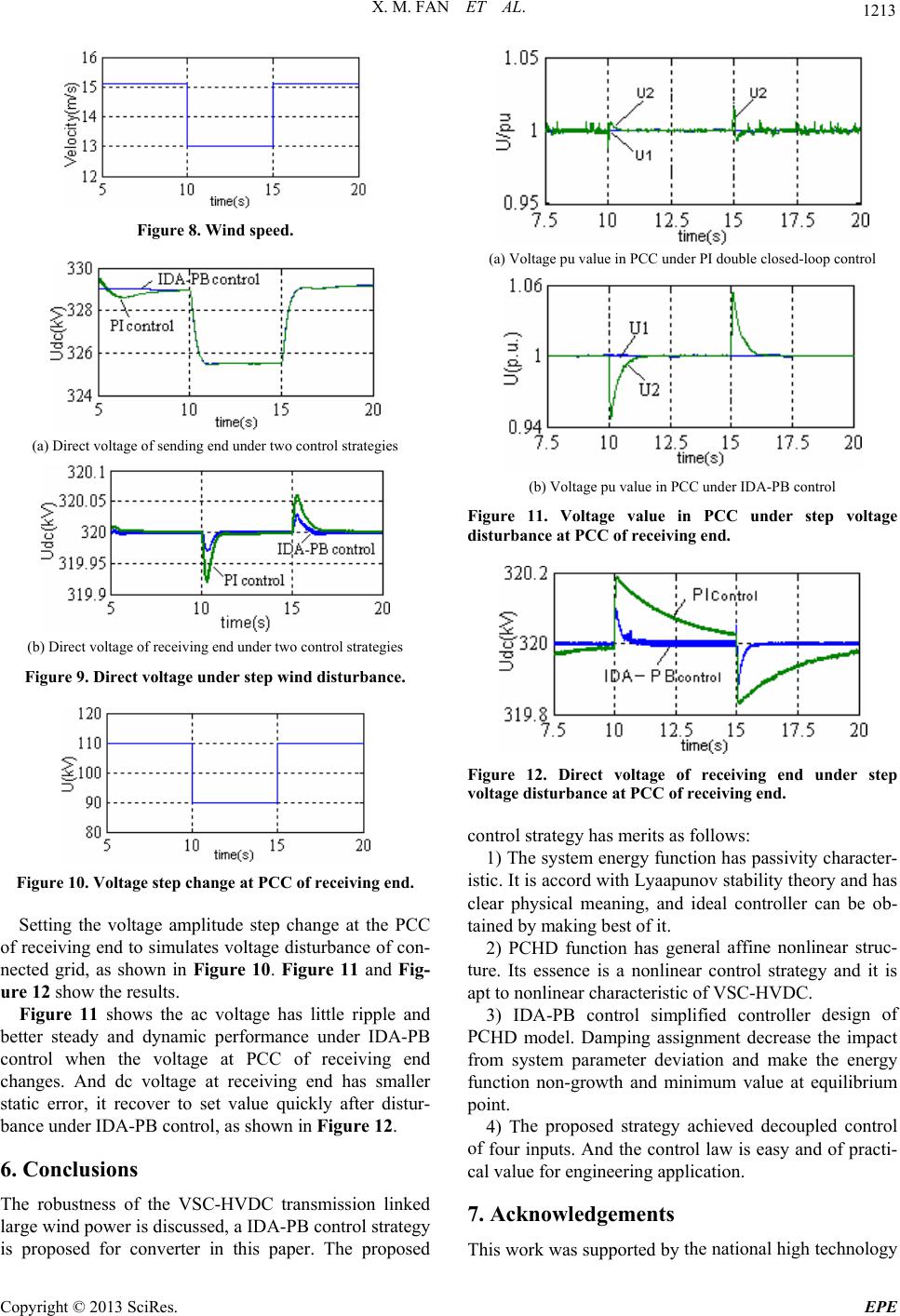 X. M. FAN ET AL. 1213 Figure 8. Wind speed. (a) Direct voltage of sending end under two control st rategies (b) Direct voltage of receiving end under two control strategies F igure 9. Direct voltage under step wind disturbance. Figure 10. Voltage step change at PCC of receiving end. Setting the voltage amplitude step change at the PCC of ac voltage has little ripple and be he VSC-HVDC transmission linked receiving end to simulates voltage disturbance of con- nected grid, as shown in Figure 10. Figure 11 and Fig- ure 12 show the results. Figure 11 shows the tter steady and dynamic performance under IDA-PB control when the voltage at PCC of receiving end changes. And dc voltage at receiving end has smaller static error, it recover to set value quickly after distur- bance under IDA-PB control, as shown in Figure 1 2. 6. Conclusions The robustness of t large wind power is discussed, a IDA-PB control strategy is proposed for converter in this paper. The proposed (a) Voltage pu value in P CC under PI double clo sed-loop control (b) Voltage pu value in PCC under IDA-PB control Figure voltage 11. Voltage value in PCC under step disturbance at PCC of receiving end. Figure 12. Direct voltage of receiving end under step ontrol strategy has merits as follows: ssivity character- is neral affine nonlinear struc- tu esign of PC he proposed strategy achieved decoupled control of 7. Acknowledgements the national high technology voltage disturbance at PCC of receiving end. c1) The system energy function has pa tic. It is accord with Lyaapunov stability th eory and has clear physical meaning, and ideal controller can be ob- tained by making best of it. 2) PCHD function has ge re. Its essence is a nonlinear control strategy and it is apt to nonlinear characteristic of VSC-HVDC. 3) IDA-PB control simplified controller d HD model. Damping assignment decrease the impact from system parameter deviation and make the energy function non-growth and minimum value at equilibrium point. 4) T four inputs. And the control law is easy and of practi- cal value for engineering application. This work was supported by C opyright © 2013 SciRes. EPE 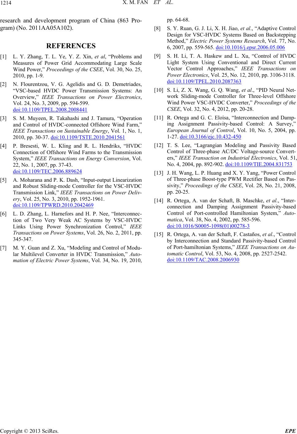 X. M. FAN ET AL. Copyright © 2013 SciRes. EPE 1214 REFERENCES [1] L. Y. Zhang, al, “Problem , V. G. Agelidis and G. D. Demetriades, research and development program of China (863 Pro- gram) (No. 2011AA05A102). T. L. Ye, Y. Z. Xin, et s and Measures of Power Grid Accommodating Large Scale Wind Power,” Proceedings of the CSEE, Vol. 30, No. 25, 2010, pp. 1-9. [2] N. Flourentzou “VSC-based HVDC Power Transmission Systems: An Overview,” IEEE Transactions on Power Electronics, Vol. 24, No. 3, 2009, pp. 594-599. doi:10.1109/TPEL.2008.2008441 [3] S. M. Muyeen, R. Takahashi and J. Tamura, “Operation and Control of HVDC-connected Offshore Wind Farm,” IEEE Transactions on Sustainable Energy, Vol. 1, No. 1, 2010, pp. 30-37. doi:10.1109/TSTE.2010.2041561 [4] P. Bresesti, W. L. Kling and R. L. Hendriks, “HVDC Connection of Offshore Wind Farms to the Transmission System,” IEEE Transactions on Energy Conversion, Vol. 22, No. 1, 2007, pp. 37-43. doi:10.1109/TEC.2006.889624 [5] A. Moharana and P. K. Dash, “Input-output Linearization and Robust Sliding-mode Controller for the VSC-HVDC Transmission Link,” IEEE Transactions on Power Deliv- ery, Vol. 25, No. 3, 2010, pp. 1952-1961. doi:10.1109/TPWRD.2010.2042469 [6] L. D. Zhang, L. Harnefors and H. P. Nee, “Interconnec- and Z. Xu, “Modeling and Control of Modu- tion of Two Very Weak AC Systems by VSC-HVDC Links Using Power Synchronization Control,” IEEE Transactions on Power Systems, Vol. 26, No. 2, 2011, pp. 345-347. [7] M. Y. Guan lar Multilevel Converter in HVDC Transmission,” Auto- mation of Electric Power Systems, Vol. 34, No. 19, 2010, pp. 64-68. [8] S. Y. Ruan, G. J. Li, X. H. Jiao, et al., “Adaptive Control Design for VSC-HVDC Systems Based on Backstepping Method,” Electric Power Systems Research, Vol. 77, No. 6, 2007, pp. 559-565. doi:10.1016/j.epsr.2006.05.006 [9] S. H. Li, T. A. Haskew and L. Xu, “Control of HVDC Light System Using Conventional and Direct Current Vector Control Approaches,” IEEE Transactions on Power Electronics, Vol. 25, No. 12, 2010, pp. 3106-3118. doi:10.1109/TPEL.2010.2087363 [10] S. Li, Z. X. Wang, G. Q. Wang, et al., “PID Neural Net- work Sliding-mode Controller for Three-level Offshore Wind Power VSC-HVDC Converter,” Proceedings of the CSEE, Vol. 32, No. 4, 2012, pp. 20-28. [11] R. Ortega and G. C. Eloísa, “Interconnection and Damp- ing Assignment Passivity-based Control: A Survey,” European Journal of Control, Vol. 10, No. 5, 2004, pp. 1-27. doi:10.3166/ejc.10.432-450 [12] T. S. Lee, “Lagrangian Modeling and Passivity Based Control of Three-phase AC/DC Voltage-source Convert- ers,” IEEE Transaction on Industrial Electronics, Vol. 51, No. 4, 2004, pp. 892-902. doi:10.1109/TIE.2004.831753 [13] J. H. Wang, L. P. Huang and X. Y. Yang, “Power Control of Three-phase Boost-type PWM Rectifier Based on Pas- sivity,” Proceedings of the CSEE, Vol. 28, No. 21, 2008, pp. 20-25. [14] R. Ortega, A. van der Schaft, B. Maschke, et al., “Inter- connection and Damping Assignment Passivity-based Control of Port-controlled Hamiltonian System,” Auto- matica, Vol. 38, No. 4, 2002, pp. 585-596. doi:10.1016/S0005-1098(01)00278-3 [15] R. Ortega, A. van der Schaft, F. Castaños, et al., “Control by Interconnection and Standard Passivity-based Control of Port-hamiltonian Systems,” IEEE Transactions on Au- tomatic Control, Vol. 53, No. 4, 2008, pp. 2527-2542. doi:10.1109/TAC.2008.2006930 |