

Paper Menu >>
Journal Menu >>
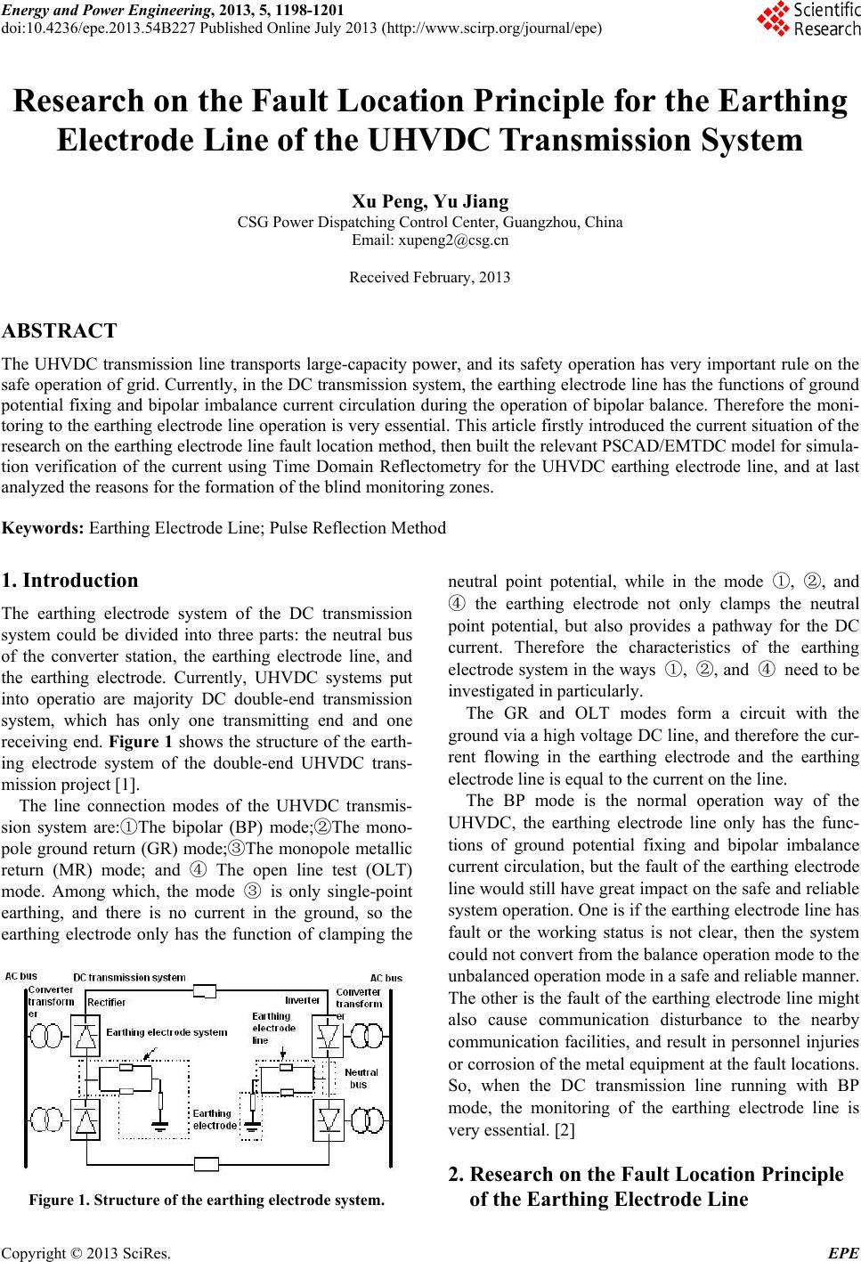 Energy and Power Engineering, 2013, 5, 1198-1201 doi:10.4236/epe.2013.54B227 Published Online July 2013 (http://www.scirp.org/journal/epe) Research on the Fault Location Principle for the Earthing Electrode Line of the UHVDC Transmission System Xu Peng, Yu Jiang CSG Power Dispatching Control Center, Guangzhou, China Email: [email protected] Received February, 2013 ABSTRACT The UHVDC transmission line transports large-capacity power, and its safety operation has very important rule on the safe operation of grid. Currently, in the DC transmission system, the earthing electrode line has th e functions of ground potential fixing and bipolar imbalance current circulation during the operation of bipolar balance. Therefore the moni- toring to the earthing electrode line operation is very essential. This article firstly introduced the curren t situation of the research on the earthing electrod e line fault locatio n method, then bu ilt the relevant PSCAD/EMTDC model for simula- tion verification of the current using Time Domain Reflectometry for the UHVDC earthing electrode line, and at last analyzed the reasons for the formation of the blind monitoring zones. Keywords: Earthing Electrode Line; Pulse Reflection Method 1. Introduction The earthing electrode system of the DC transmission system could be divided into three parts: the neutral bus of the converter station, the earthing electrode line, and the earthing electrode. Currently, UHVDC systems put into operatio are majority DC double-end transmission system, which has only one transmitting end and one receiving end. Figure 1 shows the structure of the earth- ing electrode system of the double-end UHVDC trans- mission project [1]. The line connection modes of the UHVDC transmis- sion system are:①The bipolar (BP) mode;②The mono- pole ground return (GR) mode;③The monopole metallic return (MR) mode; and ④ The open line test (OLT) mode. Among which, the mode ③ is only single-point earthing, and there is no current in the ground, so the earthing electrode only has the function of clamping the Figure 1. Structure of the earthing electrode system. neutral point potential, while in the mode ①, ②, and ④ the earthing electrode not only clamps the neutral point potential, but also provides a pathway for the DC current. Therefore the characteristics of the earthing electrode system in the ways ①, ②, and ④ need to be investigated in particu larly. The GR and OLT modes form a circuit with the ground via a high voltage DC line, and therefore the cur- rent flowing in the earthing electrode and the earthing electrode line is equal to the curren t on the line. The BP mode is the normal operation way of the UHVDC, the earthing electrode line only has the func- tions of ground potential fixing and bipolar imbalance current circulation, but the fault of the earthing electrode line would still h ave great impact on the safe and reliable system operation. One is if the earthing electrode line has fault or the working status is not clear, then the system could not convert fro m the balance oper ation mode to the unbalanced operation mode in a safe and reliable manner. The other is the fault of the earthing electrode line might also cause communication disturbance to the nearby communication facilities, and result in personnel injuries or corrosion of the metal equipment at the fault lo cations. So, when the DC transmission line running with BP mode, the monitoring of the earthing electrode line is very essential. [2] 2. Research on the Fault Location Principle of the Earthing Electrode Line Copyright © 2013 SciRes. EPE 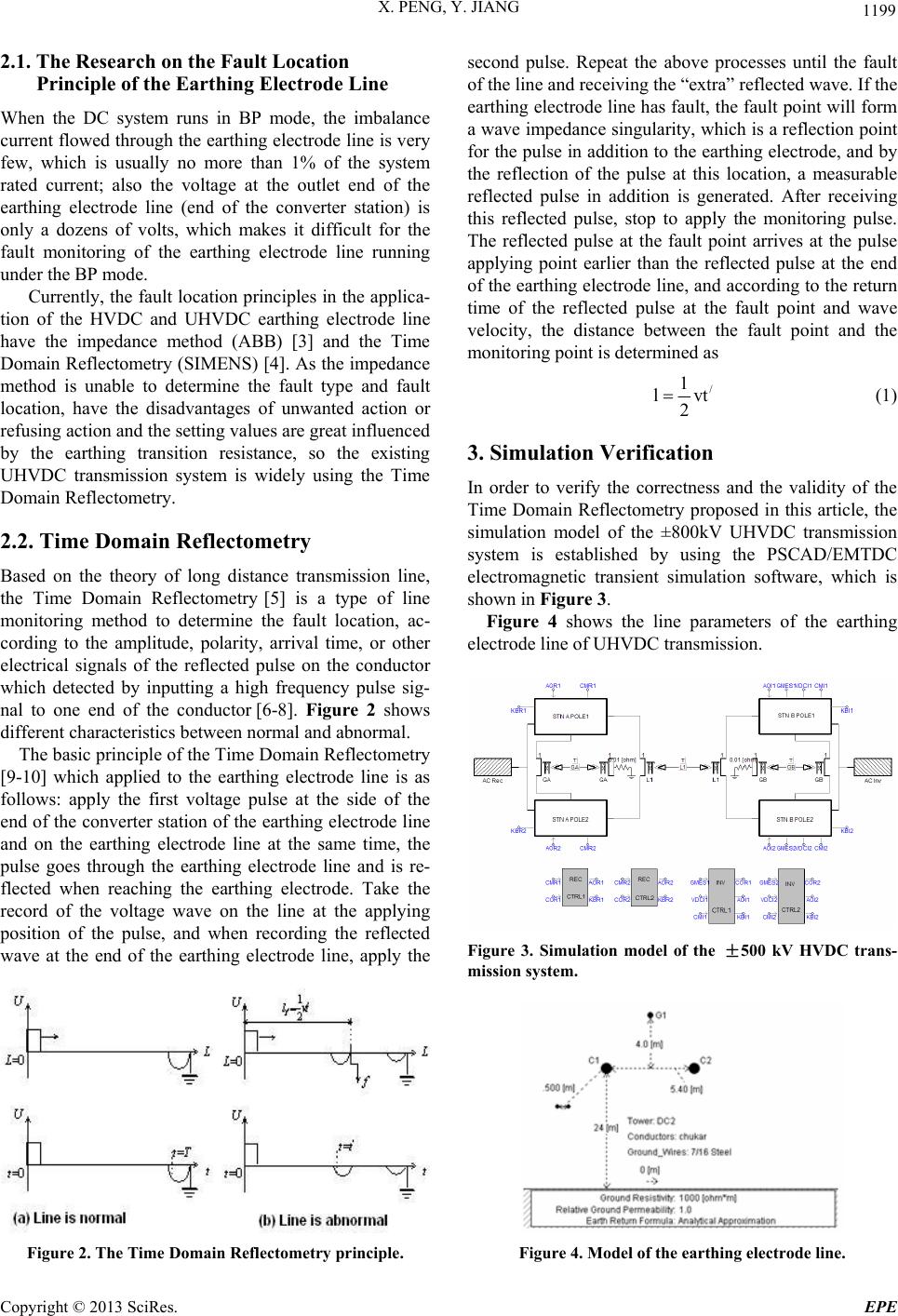 X. PENG, Y. JIANG 1199 2.1. The Research on the Fault Location Principle of the Earthing Electrode Line When the DC system runs in BP mode, the imbalance current flowed through the earthing electrode line is very few, which is usually no more than 1% of the system rated current; also the voltage at the outlet end of the earthing electrode line (end of the converter station) is only a dozens of volts, which makes it difficult for the fault monitoring of the earthing electrode line running under the BP mode. Currently, th e fault location principles in the applica- tion of the HVDC and UHVDC earthing electrode line have the impedance method (ABB) [3] and the Time Domain Reflectometry (SIMENS) [4]. As the impedance method is unable to determine the fault type and fault location, have the disadvantages of unwanted action or refusing action and the settin g valu es are great in fluen ced by the earthing transition resistance, so the existing UHVDC transmission system is widely using the Time Domain Reflectometry. 2.2. Time Domain Reflectometry Based on the theory of long distance transmission line, the Time Domain Reflectometry [5] is a type of line monitoring method to determine the fault location, ac- cording to the amplitude, polarity, arrival time, or other electrical signals of the reflected pulse on the conductor which detected by inputting a high frequency pulse sig- nal to one end of the conductor [6-8]. Figure 2 shows different characteristics between normal and abnormal. The basic principle of the Time Domain Reflectometry [9-10] which applied to the earthing electrode line is as follows: apply the first voltage pulse at the side of the end of the converter station of the earthing electrode line and on the earthing electrode line at the same time, the pulse goes through the earthing electrode line and is re- flected when reaching the earthing electrode. Take the record of the voltage wave on the line at the applying position of the pulse, and when recording the reflected wave at the end of the earthing electrode line, apply the Figure 2. The Time Domain Reflectometry principle. second pulse. Repeat the above processes until the fault of the line and receiving the “extra” reflected wave. If the earthing electrode line has fault, the fault poin t will form a wave impedance singularity, which is a reflection point for the pulse in addition to the earthing electrode, and by the reflection of the pulse at this location, a measurable reflected pulse in addition is generated. After receiving this reflected pulse, stop to apply the monitoring pulse. The reflected pulse at the fault point arrives at the pulse applying point earlier than the reflected pulse at the end of the earthing electrode line, and according to the return time of the reflected pulse at the fault point and wave velocity, the distance between the fault point and the monitoring point is determined as / 1 lv 2 t (1) 3. Simulation Verification In order to verify the correctness and the validity of the Time Domain Reflectometry proposed in this article, the simulation model of the ±800kV UHVDC transmission system is established by using the PSCAD/EMTDC electromagnetic transient simulation software, which is shown in Figure 3. Figure 4 shows the line parameters of the earthing electrode line of UHVDC transmission. Figure 3. Simulation model of the ±500 kV HVDC trans- mission system. Figure 4. Model of the e arthing electrode line. Copyright © 2013 SciRes. EPE  X. PENG, Y. JIANG 1200 Normal line Single-line earthing short circuit fault Double-line earthing short circuit fault Double-line short circuit fault Single-line disconnection fault Double-line disconnection fault Figure 5. Results of the PSCAD/EMTDC simulation for various fault types. Transmit a pulse with amplitude U = 150 V and pulse width tp= 30 µs at the start side of the earthing electrode line at 1s (2s as a cycle). Figure 5 shows the PSCAD/ EMTDC simulation results of the pulse on the earthing electrode line when the different fault types occured at the neutral point of the UHVDC earthing electrode line. It is conclued from Figure 5: polarities of the reflec- tion pulse and the transmission pulse under disconnection fault is same, while under earthing faul is opposite, and the fault type of the earthing electrode line could be de- duced based on the polarity of the reflection pulse. For the metallic short circuits of the earthing electrode line happed at different locations and different types, this article also made the PSCAD/EMTDC simulation, take the sampling frequency fs = 100 kHz, v = 2.97×10⁸ m/s. The fault location is shown in Table 1. The simulation result in Table 1 shows, in the case of metallic faults, there are certain blind detection zones at the start side (transmission side) and the end side of the line; and the longer the fault distance, the bigger the fault location error sh ows. Within the range of 25% to 75% of the line, the maximum actual error and the maximum relative error of the fault location are 2.042 km and 1.442% in separately. Reasons for the occurred detection blind zones: 1) As shown in Figure 6, the transmission pulse can not separated from the reflection pulse at the start side fault. The reason is, the transmission pulse itself occupies a certain period of time, when the fault point is very close by, the reflection pulse shows almost simultane- ously with the transmission pu lse, as the amp litud e of the transmission pulse is large and also exist when the line has no short circuit, and therefore the transmission pulse can not separated from the reflection pulse by fault near by the start side, also the fault location of the start side could not be identifi e d. As shown in Figure 7, the reflection pulse at the end side fault can not separated from the fixed reflection pulse of the earthing electrode resistance. This is because when the fault point at the end side is very close to the earthing electrode resistance, the reflection pulse by fault also shows up almost simultaneously with the fixed re- flection pulse and with almost equal amplitude, the two reflection pulses are superimposed, and therefore the reflection pulse at the end side fault can not separated from the fixed reflection pulse of the earthing electrode resistance, also the fault location of the end side could not be identified. Table 1. Results of fault location under metallic faults (km). Method of the article Fault typeFault location Simulation result Actual error Relative error 2% Can not identified Can not identified Can not identified 25% 47.52 0.309 0.655% 50% 93.555 -0.867 0.918% 75% 139.59 -2.042 1.442% Single-line short cir- cuit earthing 98% Can not identified Can not identified Can not identified 2% Can not identified Can not identified Can not identified 25% 47.52 0.309 0.655% 50% 93.555 -0.867 0.918% 75% 139.59 -2.042 1.442% Dou- ble-line short cir- cuit earthing 98% Can not identified Can not identified Can not identified Figure 6. Single-line short circuit earthing (lF=2%l). Copyright © 2013 SciRes. EPE  X. PENG, Y. JIANG Copyright © 2013 SciRes. EPE 1201 Figure 7. Double-line short circuit earthing (lF = 98%l). 4. Summary Aiming at the current situation that the Time Domain Reflectometry is used for fault location of the earthing electrode line of the UHVDC system, this article de- scribed the principle of the Time Domain Reflectometry, established corresponding PSCAD/EMTDC model for simulation verification, analyzed the error precision of the Time Domain Reflectometry, pointed out the reasons for the formation of the monitoring blind zones, and con- structed the foundation for the further study of the fault location principle of the earthing electrode line of the UHVDC transmission system. REFERENCES [1] DC transmission Scientific Research Group of Power Generation Teaching and Research Center of Zhejiang University, “DC transmission,” Beijing, Publishing house of electric power industry, 1982, pp. 6-8. [2] W. J. Zhao, “HVDC Transmission Engineering Technol- ogy,” Beijing: China Electric Power Publishing House, 2007, pp.1-3. [3] Nanjing Nari-relays Electric Co., Ltd., “Design Specifica- tion for Earthing Electrode Line Monitoring,” 2009. [4] “Maintenance Manuals of Electrode Line Monitor- ing,”Siemens, 2007. [5] Y. S. Gong, Z. Z. Li and C. Y. Li, “Evapotranspiration Assessed According to Soil Water Content Measured by the Time Domain Reflectometer,” Journal of applied me- teorological science,Vol. 9,No. 1,1998, pp.72-78. [6] Q. Meng, “Research Development and Its Application in the Irrigation of the Time Domain Reflectometer,” Water Saving Irrigation, 1999, pp.1-3. [7] S. D. Logsdon, “Effect of Cable Length on Time Domain Reflectometry Calibration for High Surface Area Soils,” Soil Science Society America, Vol. 64, No. 1, 2000, pp. 54-61. doi:10.2136/sssaj2000.64154x [8] W. F. Kane, “Monitoring Slope Movement with Time Domain Reflectometry,” Applications for Engineers and Geologists, 2000, pp.1-8. [9] J. Ammon, G. Plewka and G. Schaller, “Method and De- vice for the Electrical Monitoring of An Electrode Lead of A Bipolar HVDC Transmission System,” US Pat ent No.6518769 B1, 2003 [10] G. Asplund, “Electrode Line Protection,” US Patent No. 5117323,1992 |