

Paper Menu >>
Journal Menu >>
 Open Journal of Stomatology, 2013, 3, 425-432 OJST http://dx.doi.org/10.4236/ojst.2013.38071 Published Online November 2013 (http://www.scirp.org/journal/ojst/) Dentoalveolar changes following maxillary distraction osteogenesis Lili Yang1, Eduardo Yugo Suzuki2*, Boonsiva Suzuki2 1Faculty of Dentistry, Chiang Mai University, Chiang Mai, Thailand 2Department of Orthodontics and Pediatric Dentistry, Faculty of Dentistry, Chiang Mai University, Chiang Mai, Thailand Email: *[email protected] Received 20 August 2012; revised 23 September 2013; accepted 15 October 2013 Copyright © 2013 Lili Yang et al. This is an open access article distributed under the Creative Commons Attribution License, which permits unrestricted use, distribution, and reproduction in any medium, provided the original work is properly cited. ABSTRACT The purpose of this study was to compare the den- toalveolar changes produced when using two differ- ent intraoperative surgical procedures for maxillary distraction osteogenesis. Eight patients were assigned into two groups according to the surgical procedure: down-fracture (DF, n = 6) vs non-down-fracture (NDF, n = 2). Lateral cephalograms and 3-D models before and after maxillary distraction were analyzed. The Mann-Whitney U test was used to compare the differences in the amounts of advancement and dento-alveolar changes between the DF and NDF groups. The significance level was established at 0.05. Although a significantly greater amount of maxillary movement was observed in the DF group (10.0 mm ± 2.2) than in the NDF group (5.9 mm ± 2.3), signifi- cantly greater arch length (8.7 mm ± 5.2) and arch width changes (6.0 mm ± 1.0) were observed in the NDF group than in the DF group, (arch lengths 3.0 mm ± 1.1 and arch width changes 3.2 mm ± 2.0). A significantly greater amount of dental anchorage loss was observed in the NDF group. The use of the NDF procedure resulted in greater amounts of dental an- chorage loss than resulted from the DF procedures when tooth-borne devices were used during maxillary distraction osteogenesis. The type of surgical proce- dure might play an important role in the amount and direction of the dental changes. Keywords: Maxillary Distraction; Non-Down-Fracture; Down-Fracture; 3-D Model Analysis 1. INTRODUCTION Distraction osteogenesis is a biomechanical process where the application of incremental traction forces leads to new bone formation between the surfaces of osteoto- mized bone segments that are gradually separated [1,2]. This technique not only allows the development of in- crements of new bone, but also allows the stretching of the surrounding soft tissue [3-5]. Therefore, distraction osteogenesis has become a very important alternative in the treatment of patients with severe maxillary hypopla- sia in craniofacial syndromes and cleft-related deformi- ties [6,7]. Maxillary distraction osteogenesis has been applied successfully for the management of patients with clefts and has several advantages over conventional orthog- nathic procedures. These advantages, such as allowing large amounts of maxillary advancement [6,7], thus eliminating the need for bone grafting, have reduced rates of relapse [8]. Conventional surgical procedures for maxillary dis- traction osteogenesis often involve a Le Fort I complete osteotomy with pterygomaxillary disjunction, septal dis- junction and careful medial sinus wall separation fol- lowed by an intraoperative DF to achieve the complete mobilization of the maxilla [9,10]. However, the DF is considered as a high-risk and aggressive procedure, since it may induce undesirable fractures extended to the pterygoid plate, sphenoid bone and cranial base, edema and bleeding [11]. In order to minimize the risk of the surgical procedure and to shorten the operation time, the use of maxillary osteotomy without the complete intra- operative DF, also known as the NDF technique, has been proposed by several authors [3,12,13]. In the NDF technique, the maxilla is mobilized just enough to ensure that the skeletal osteotomy has been completed [12]. Therefore, the traditional and aggressive DF procedure is not fully performed [12,13]. Some reports have shown that cases treated without the DF technique allow for sufficient mobilization of the maxillary bone, consequently providing similar surgical outcomes to those of cases treated with the conventional *Corresponding author. OPEN ACCESS 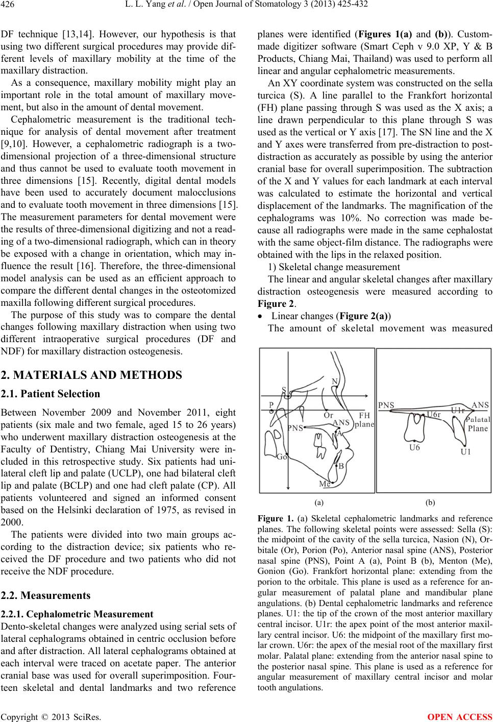 L. L. Yang et al. / Open Journal of Stomatology 3 (2013) 425-432 426 DF technique [13,14]. However, our hypothesis is that using two different surgical procedures may provide dif- ferent levels of maxillary mobility at the time of the maxillary distraction. As a consequence, maxillary mobility might play an important role in the total amount of maxillary move- ment, but also in the amount of dental movement. Cephalometric measurement is the traditional tech- nique for analysis of dental movement after treatment [9,10]. However, a cephalometric radiograph is a two- dimensional projection of a three-dimensional structure and thus cannot be used to evaluate tooth movement in three dimensions [15]. Recently, digital dental models have been used to accurately document malocclusions and to evaluate tooth movement in three dimensions [15]. The measurement parameters for dental movement were the results of three-dimensional digitizing and not a read- ing of a two-dimensional radiograph, which can in theory be exposed with a change in orientation, which may in- fluence the result [16]. Therefore, the three-dimensional model analysis can be used as an efficient approach to compare the different dental changes in the osteotomized maxilla following different surgical procedures. The purpose of this study was to compare the dental changes following maxillary distraction when using two different intraoperative surgical procedures (DF and NDF) for maxillary distraction osteogenesis. 2. MATERIALS AND METHODS 2.1. Patient Selection Between November 2009 and November 2011, eight patients (six male and two female, aged 15 to 26 years) who underwent maxillary distraction osteogenesis at the Faculty of Dentistry, Chiang Mai University were in- cluded in this retrospective study. Six patients had uni- lateral cleft lip and palate (UCLP), one had bilateral cleft lip and palate (BCLP) and one had cleft palate (CP). All patients volunteered and signed an informed consent based on the Helsinki declaration of 1975, as revised in 2000. The patients were divided into two main groups ac- cording to the distraction device; six patients who re- ceived the DF procedure and two patients who did not receive the NDF procedure. 2.2. Measurements 2.2.1. Cephalometric Measurement Dento-skeletal changes were analyzed using serial sets of lateral cephalograms obtained in centric occlusion before and after distraction. All lateral cephalograms obtained at each interval were traced on acetate paper. The anterior cranial base was used for overall superimposition. Four- teen skeletal and dental landmarks and two reference planes were identified (Figures 1(a) and (b)). Custom- made digitizer software (Smart Ceph v 9.0 XP, Y & B Products, Chiang Mai, Thailand) was used to perform all linear and angular cephalometric measurements. An XY coordinate system was constructed on the sella turcica (S). A line parallel to the Frankfort horizontal (FH) plane passing through S was used as the X axis; a line drawn perpendicular to this plane through S was used as the vertical or Y axis [17]. The SN line and the X and Y axes were transferred from pre-distraction to post- distraction as accurately as possible by using the anterior cranial base for overall superimposition. The subtraction of the X and Y values for each landmark at each interval was calculated to estimate the horizontal and vertical displacement of the landmarks. The magnification of the cephalograms was 10%. No correction was made be- cause all radiographs were made in the same cephalostat with the same object-film distance. The radiographs were obtained with the lips in the relaxed position. 1) Skeletal change measurement The linear and angular skeletal changes after maxillary distraction osteogenesis were measured according to Figure 2. Linear changes (Figure 2( a) ) The amount of skeletal movement was measured (a) (b) Figure 1. (a) Skeletal cephalometric landmarks and reference planes. The following skeletal points were assessed: Sella (S): the midpoint of the cavity of the sella turcica, Nasion (N), Or- bitale (Or), Porion (Po), Anterior nasal spine (ANS), Posterior nasal spine (PNS), Point A (a), Point B (b), Menton (Me), Gonion (Go). Frankfort horizontal plane: extending from the porion to the orbitale. This plane is used as a reference for an- gular measurement of palatal plane and mandibular plane angulations. (b) Dental cephalometric landmarks and reference planes. U1: the tip of the crown of the most anterior maxillary central incisor. U1r: the apex point of the most anterior maxil- lary central incisor. U6: the midpoint of the maxillary first mo- lar crown. U6r: the apex of the mesial root of the maxillary first molar. Palatal plane: extending from the anterior nasal spine to the posterior nasal spine. This plane is used as a reference for angular measurement of maxillary central incisor and molar tooth angulations. Copyright © 2013 SciRes. OPEN ACCESS 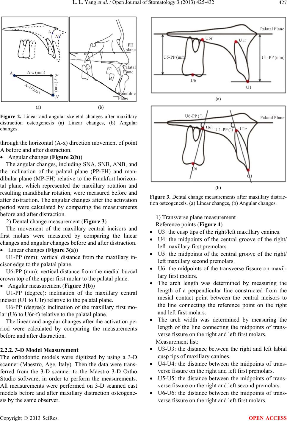 L. L. Yang et al. / Open Journal of Stomatology 3 (2013) 425-432 427 (a) (b) Figure 2. Linear and angular skeletal changes after maxillary distraction osteogenesis (a) Linear changes, (b) Angular changes. through the horizontal (A-x) direction movement of point A before and after distraction. Angular changes (Figure 2( b )) The angular changes, including SNA, SNB, ANB, and the inclination of the palatal plane (PP-FH) and man- dibular plane (MP-FH) relative to the Frankfort horizon- tal plane, which represented the maxillary rotation and resulting mandibular rotation, were measured before and after distraction. The angular changes after the activation period were calculated by comparing the measurements before and after distraction. 2) Dental change measurement (Figure 3) The movement of the maxillary central incisors and first molars were measured by comparing the linear changes and angular changes before and after distraction. Linear changes (Figure 3( a) ) U1-PP (mm): vertical distance from the maxillary in- cisor edge to the palatal plane. U6-PP (mm): vertical distance from the medial buccal crown top of the upper first molar to the palatal plane. Angular measurement (Figure 3(b)) U1-PP (degree): inclination of the maxillary central incisor (U1 to U1r) relative to the palatal plane. U6-PP (degree): inclination of the maxillary first mo- lar (U6 to U6r-f) relative to the palatal plane. The linear and angular changes after the activation pe- riod were calculated by comparing the measurements before and after distraction. 2.2.2. 3-D Model Measurement The orthodontic models were digitized by using a 3-D scanner (Maestro, Age, Italy). Then the data were trans- ferred from the 3-D scanner to the Maestro 3-D Ortho Studio software, in order to perform the measurements. All measurements were performed on 3-D scanned cast models before and after maxillary distraction osteogene- sis by the same observer. (a) (b) Figure 3. Dental change measurements after maxillary distrac- tion osteogenesis. (a) Linear changes, (b) Angular changes. 1) Transverse plane measurement Reference points (Figure 4) U3: the cusp tips of the right/left maxillary canines. U4: the midpoints of the central groove of the right/ left maxillary first premolars. U5: the midpoints of the central groove of the right/ left maxillary second premolars. U6: the midpoints of the transverse fissure on maxil- lary first molars. The arch length was determined by measuring the length of a perpendicular line constructed from the mesial contact point between the central incisors to the line connecting the reference point on the right and left first molars. The arch width was determined by measuring the length of the line connecting the midpoints of trans- verse fissure on the right and left first molars. Measurement list: U3-U3: the distance between the right and left labial cusp tips of maxillary canines. U4-U4: the distance between the midpoints of trans- verse fissure on the right and left first premolars. U5-U5: the distance between the midpoints of trans- verse fissure on the right and left second premolars. U6-U6: the distance between the midpoints of trans- verse fissure on the right and left first molars. Copyright © 2013 SciRes. OPEN ACCESS 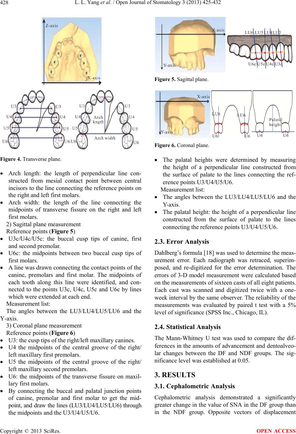 L. L. Yang et al. / Open Journal of Stomatology 3 (2013) 425-432 428 Figure 4. Transverse plane. Arch length: the length of perpendicular line con- structed from mesial contact point between central incisors to the line connecting the reference points on the right and left first molars. Arch width: the length of the line connecting the midpoints of transverse fissure on the right and left first molars. 2) Sagittal plane measurement Reference points (Figure 5) U3c/U4c/U5c: the buccal cusp tips of canine, first and second premolar. U6c: the midpoints between two buccal cusp tips of first molars. A line was drawn connecting the contact points of the canine, premolars and first molar. The midpoints of each tooth along this line were identified, and con- nected to the points U3c, U4c, U5c and U6c by lines which were extended at each end. Measurement list: The angles between the LU3/LU4/LU5/LU6 and the Y-axis. 3) Coronal plane measurement Reference points (Figure 6) U3: the cusp tips of the right/left maxillary canines. U4 the midpoints of the central groove of the right/ left maxillary first premolars. U5 the midpoints of the central groove of the right/ left maxillary second premolars. U6: the midpoints of the transverse fissure on maxil- lary first molars. By connecting the buccal and palatal junction points of canine, premolar and first molar to get the mid- point, and draw the lines (LU3/LU4/LU5/LU6) through the midpoints and the U3/U4/U5/U6. Figure 5. Sagittal plane. Figure 6. Coronal plane. The palatal heights were determined by measuring the height of a perpendicular line constructed from the surface of palate to the lines connecting the ref- erence points U3/U4/U5/U6. Measurement list: The angles between the LU3/LU4/LU5/LU6 and the Y- ax is. The palatal height: the height of a perpendicular line constructed from the surface of palate to the lines connecting the reference points U3/U4/U5/U6. 2.3. Error Analysis Dahlberg’s formula [18] was used to determine the meas- urement error. Each radiograph was retraced, superim- posed, and re-digitized for the error determination. The errors of 3-D model measurement were calculated based on the measurements of sixteen casts of all eight patients. Each cast was scanned and digitized twice with a one- week interval by the same observer. The reliability of the measurements was evaluated by paired t test with a 5% level of significance (SPSS Inc., Chicago, IL). 2.4. Statistical Analysis The Mann-Whitney U test was used to compare the dif- ferences in the amounts of advancement and dentoalveo- lar changes between the DF and NDF groups. The sig- nificance level was established at 0.05. 3. RESULTS 3.1. Cephalometric Analysis Cephalometric analysis demonstrated a significantly greater change in the value of SNA in the DF group than in the NDF group. Opposite vectors of displacement Copyright © 2013 SciRes. OPEN ACCESS 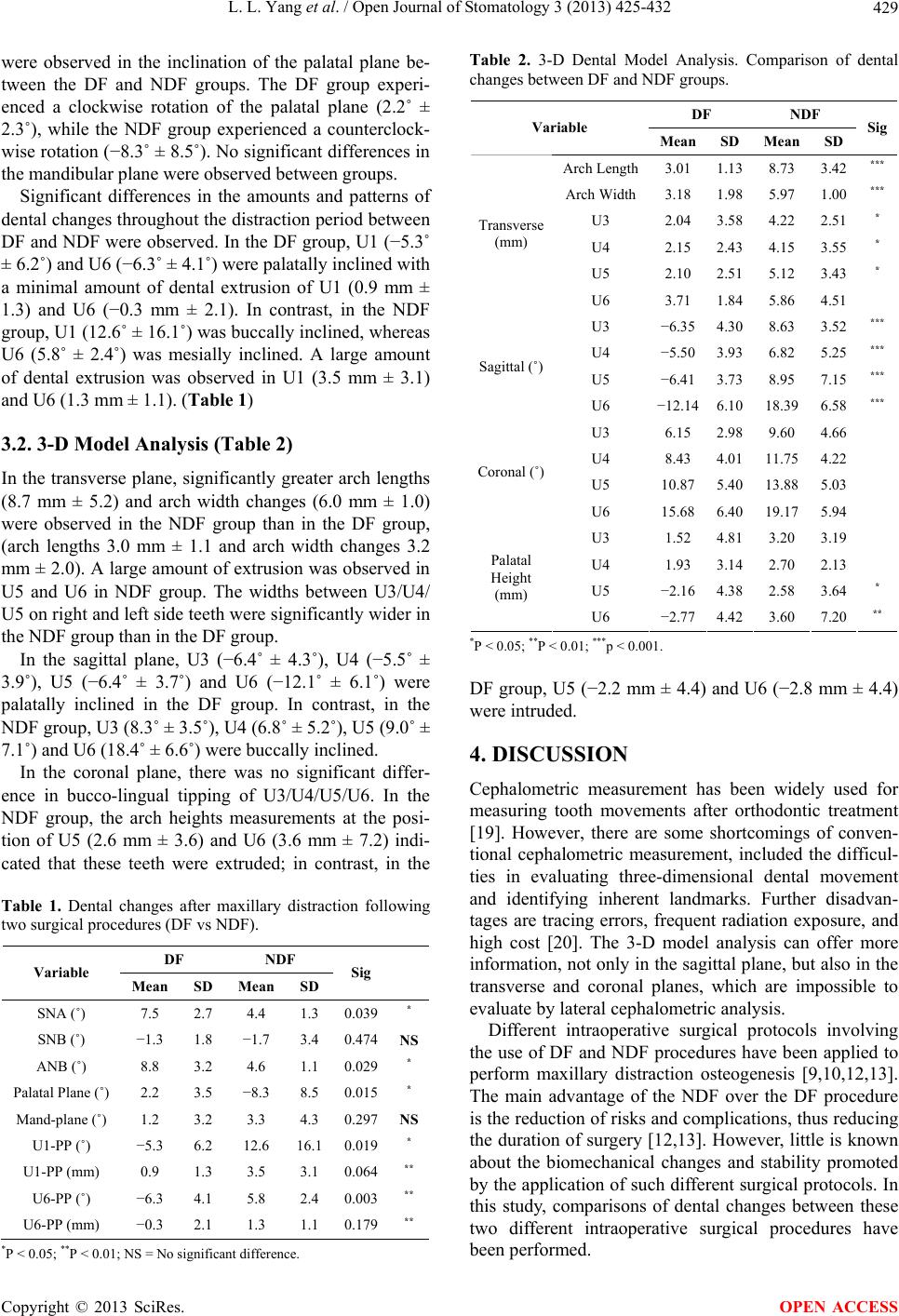 L. L. Yang et al. / Open Journal of Stomatology 3 (2013) 425-432 429 were observed in the inclination of the palatal plane be- tween the DF and NDF groups. The DF group experi- enced a clockwise rotation of the palatal plane (2.2˚ ± 2.3˚), while the NDF group experienced a counterclock- wise rotation (−8.3˚ ± 8.5˚). No significant differences in the mandibular plane were observed between groups. Significant differences in the amounts and patterns of dental changes throughout the distraction period between DF and NDF were observed. In the DF group, U1 (−5.3˚ ± 6.2˚) and U6 (−6.3˚ ± 4.1˚) were palatally inclined with a minimal amount of dental extrusion of U1 (0.9 mm ± 1.3) and U6 (−0.3 mm ± 2.1). In contrast, in the NDF group, U1 (12.6˚ ± 16.1˚) was buccally inclined, whereas U6 (5.8˚ ± 2.4˚) was mesially inclined. A large amount of dental extrusion was observed in U1 (3.5 mm ± 3.1) and U6 (1.3 mm ± 1.1). (Table 1) 3.2. 3-D Model Analysis (Table 2) In the transverse plane, significantly greater arch lengths (8.7 mm ± 5.2) and arch width changes (6.0 mm ± 1.0) were observed in the NDF group than in the DF group, (arch lengths 3.0 mm ± 1.1 and arch width changes 3.2 mm ± 2.0). A large amount of extrusion was observed in U5 and U6 in NDF group. The widths between U3/U4/ U5 on right and left side teeth were significantly wider in the NDF group than in the DF group. In the sagittal plane, U3 (−6.4˚ ± 4.3˚), U4 (−5.5˚ ± 3.9˚), U5 (−6.4˚ ± 3.7˚) and U6 (−12.1˚ ± 6.1˚) were palatally inclined in the DF group. In contrast, in the NDF group, U3 (8.3˚ ± 3.5˚), U4 (6.8˚ ± 5.2˚), U5 (9.0˚ ± 7.1˚) and U6 (18.4˚ ± 6.6˚) were buccally inclined. In the coronal plane, there was no significant differ- ence in bucco-lingual tipping of U3/U4/U5/U6. In the NDF group, the arch heights measurements at the posi- tion of U5 (2.6 mm ± 3.6) and U6 (3.6 mm ± 7.2) indi- cated that these teeth were extruded; in contrast, in the Table 1. Dental changes after maxillary distraction following two surgical procedures (DF vs NDF). DF NDF Variable Mean SD Mean SD Sig SNA (˚) 7.5 2.7 4.4 1.3 0.039* SNB (˚) −1.3 1.8 −1.7 3.4 0.474NS ANB (˚) 8.8 3.2 4.6 1.1 0.029* Palatal Plane (˚) 2.2 3.5 −8.3 8.5 0.015* Mand-plane (˚) 1.2 3.2 3.3 4.3 0.297NS U1-PP (˚) −5.3 6.2 12.6 16.1 0.019* U1-PP (mm) 0.9 1.3 3.5 3.1 0.064** U6-PP (˚) −6.3 4.1 5.8 2.4 0.003** U6-PP (mm) −0.3 2.1 1.3 1.1 0.179** *P < 0.05; **P < 0.01; NS = No significant difference. Table 2. 3-D Dental Model Analysis. Comparison of dental changes between DF and NDF groups. DF NDF Variable Mean SD Mean SD Sig Arch Length3.01 1.13 8.73 3.42*** Arch Width3.18 1.98 5.97 1.00*** U3 2.04 3.58 4.22 2.51* U4 2.15 2.43 4.15 3.55* U5 2.10 2.51 5.12 3.43* Transverse (mm) U6 3.71 1.84 5.86 4.51 U3 −6.35 4.30 8.63 3.52*** U4 −5.50 3.93 6.82 5.25*** U5 −6.41 3.73 8.95 7.15*** Sagittal (˚) U6 −12.14 6.10 18.39 6.58*** U3 6.15 2.98 9.60 4.66 U4 8.43 4.01 11.75 4.22 U5 10.87 5.40 13.88 5.03 Coronal (˚) U6 15.68 6.40 19.17 5.94 U3 1.52 4.81 3.20 3.19 U4 1.93 3.14 2.70 2.13 U5 −2.16 4.38 2.58 3.64* Palatal Height (mm) U6 −2.77 4.42 3.60 7.20** *P < 0.05; **P < 0.01; ***p < 0.001. DF group, U5 (−2.2 mm ± 4.4) and U6 (−2.8 mm ± 4.4) were intruded. 4. DISCUSSION Cephalometric measurement has been widely used for measuring tooth movements after orthodontic treatment [19]. However, there are some shortcomings of conven- tional cephalometric measurement, included the difficul- ties in evaluating three-dimensional dental movement and identifying inherent landmarks. Further disadvan- tages are tracing errors, frequent radiation exposure, and high cost [20]. The 3-D model analysis can offer more information, not only in the sagittal plane, but also in the transverse and coronal planes, which are impossible to evaluate by lateral cephalometric analysis. Different intraoperative surgical protocols involving the use of DF and NDF procedures have been applied to perform maxillary distraction osteogenesis [9,10,12,13]. The main advantage of the NDF over the DF procedure is the reduction of risks and complications, thus reducing the duration of surgery [12,13]. However, little is known about the biomechanical changes and stability promoted by the application of such different surgical protocols. In this study, comparisons of dental changes between these two different intraoperative surgical procedures have been performed. Copyright © 2013 SciRes. OPEN ACCESS 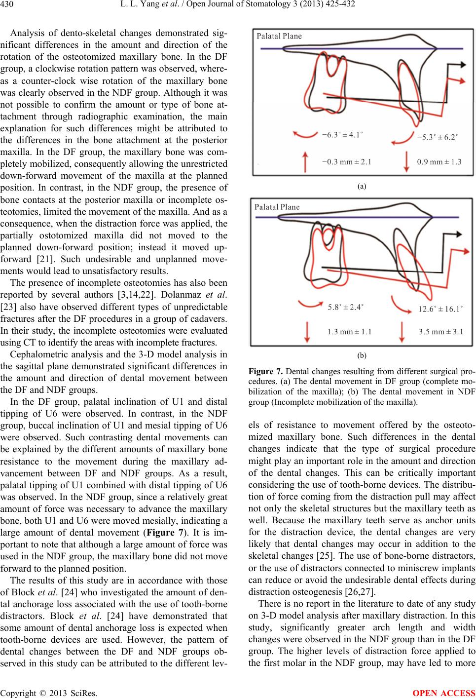 L. L. Yang et al. / Open Journal of Stomatology 3 (2013) 425-432 430 Analysis of dento-skeletal changes demonstrated sig- nificant differences in the amount and direction of the rotation of the osteotomized maxillary bone. In the DF group, a clockwise rotation pattern was observed, where- as a counter-clock wise rotation of the maxillary bone was clearly observed in the NDF group. Although it was not possible to confirm the amount or type of bone at- tachment through radiographic examination, the main explanation for such differences might be attributed to the differences in the bone attachment at the posterior maxilla. In the DF group, the maxillary bone was com- pletely mobilized, consequently allowing the unrestricted down-forward movement of the maxilla at the planned position. In contrast, in the NDF group, the presence of bone contacts at the posterior maxilla or incomplete os- teotomies, limited the movement of the maxilla. And as a consequence, when the distraction force was applied, the partially ostotomized maxilla did not moved to the planned down-forward position; instead it moved up- forward [21]. Such undesirable and unplanned move- ments would lead to unsatisfactory results. The presence of incomplete osteotomies has also been reported by several authors [3,14,22]. Dolanmaz et al. [23] also have observed different types of unpredictable fractures after the DF procedures in a group of cadavers. In their study, the incomplete osteotomies were evaluated using CT to identify the areas with incomplete fractures. Cephalometric analysis and the 3-D model analysis in the sagittal plane demonstrated significant differences in the amount and direction of dental movement between the DF and NDF groups. In the DF group, palatal inclination of U1 and distal tipping of U6 were observed. In contrast, in the NDF group, buccal inclination of U1 and mesial tipping of U6 were observed. Such contrasting dental movements can be explained by the different amounts of maxillary bone resistance to the movement during the maxillary ad- vancement between DF and NDF groups. As a result, palatal tipping of U1 combined with distal tipping of U6 was observed. In the NDF group, since a relatively great amount of force was necessary to advance the maxillary bone, both U1 and U6 were moved mesially, indicating a large amount of dental movement (Figure 7). It is im- portant to note that although a large amount of force was used in the NDF group, the maxillary bone did not move forward to the planned position. The results of this study are in accordance with those of Block et al. [24] who investigated the amount of den- tal anchorage loss associated with the use of tooth-borne distractors. Block et al. [24] have demonstrated that some amount of dental anchorage loss is expected when tooth-borne devices are used. However, the pattern of dental changes between the DF and NDF groups ob- served in this study can be attributed to the different lev- (a) (b) Figure 7. Dental changes resulting from different surgical pro- cedures. (a) The dental movement in DF group (complete mo- bilization of the maxilla); (b) The dental movement in NDF group (Incomplete mobilization of the maxilla). els of resistance to movement offered by the osteoto- mized maxillary bone. Such differences in the dental changes indicate that the type of surgical procedure might play an important role in the amount and direction of the dental changes. This can be critically important considering the use of tooth-borne devices. The distribu- tion of force coming from the distraction pull may affect not only the skeletal structures but the maxillary teeth as well. Because the maxillary teeth serve as anchor units for the distraction device, the dental changes are very likely that dental changes may occur in addition to the skeletal changes [25]. The use of bone-borne distractors, or the use of distractors connected to miniscrew implants can reduce or avoid the undesirable dental effects during distraction osteogenesis [26,27]. There is no report in the literature to date of any study on 3-D model analysis after maxillary distraction. In this study, significantly greater arch length and width changes were observed in the NDF group than in the DF group. The higher levels of distraction force applied to the first molar in the NDF group, may have led to more Copyright © 2013 SciRes. OPEN ACCESS 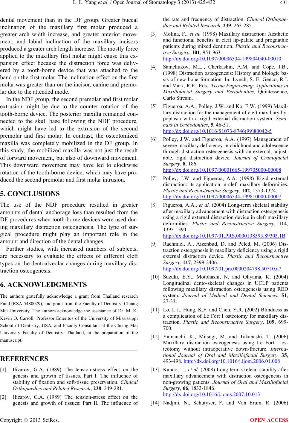 L. L. Yang et al. / Open Journal of Stomatology 3 (2013) 425-432 431 dental movement than in the DF group. Greater buccal inclination of the maxillary first molar produced a greater arch width increase, and greater anterior move- ment, and labial inclination of the maxillary incisors produced a greater arch length increase. The mostly force applied to the maxillary first molar might cause this ex- pansion effect because the distraction force was deliv- ered by a tooth-borne device that was attached to the band on the first molar. The inclination effect on the first molar was greater than on the incisor, canine and premo- lar due to the attended mode. In the NDF group, the second premolar and first molar extrusion might be due to the counter rotation of the tooth-borne device. The posterior maxilla remained con- nected to the skull base following the NDF procedure, which might have led to the extrusion of the second premolar and first molar. In contrast, the osteotomized maxilla was completely mobilized in the DF group. In this study, the mobilized maxilla was not just the result of forward movement, but also of downward movement. This downward movement may have led to clockwise rotation of the tooth-borne device, which may have pro- duced the second premolar and first molar intrusion. 5. CONCLUSIONS The use of the NDF procedure resulted in greater amounts of dental anchorage loss than resulted from the DF procedures when tooth-borne devices were used dur- ing maxillary distraction osteogenesis. The type of sur- gical procedure might play an important role in the amount and direction of the dental changes. Further studies, with increased numbers of subjects, are necessary to evaluate the effects of different cleft types on the dentoalveolar changes during maxillary dis- traction osteogenesis. 6. ACKNOWLEDGMENTS The authors gratefully acknowledge a grant from Thailand research Fund (RSA 5480029), and grant from the Faculty of Dentistry, Chiang Mai University. The authors acknowledge the assistance of Dr. M. K. Kevin O. Carroll, Professor Emeritus of the University of Mississippi School of Dentistry, USA, and Faculty Consultant at the Chiang Mai University Faculty of Dentistry, Thailand, in the preparation of the manuscript. REFERENCES [1] Ilizarov, G.A. (1989) The tension-stress effect on the genesis and growth of tissues. Part I. The influence of stability of fixation and soft-tissue preservation. Clinical Orthopaedics and Related Research, 238, 249-281. [2] Ilizarov, G.A. (1989) The tension-stress effect on the genesis and growth of tissues: Part II. The influence of the rate and frequency of distraction. Clinical Orthopae- dics and Related Research, 239, 263-285. [3] Molina, F., et al. (1998) Maxillary distraction: Aesthetic and functional benefits in cleft lip-palate and prognathic patients during mixed dentition. Plastic and Reconstruc- tive Surgery, 101, 951-963. http://dx.doi.org/10.1097/00006534-199804040-00010 [4] Samchukov, M.L., Cherkashin, A.M. and Cope, J.B., (1998) Distraction osteogenesis: History and biologic ba- sis of new bone formation. In: Lynch, S. E. Genco, R.J. and Marx, R.E., Eds., Tissue Engineering: Applications in Maxillofacial Surgery and Periodontics, Quintessence, Carlo Stream. [5] Figueroa, A.A., Polley, J.W. and Ko, E.W. (1999) Maxil- lary distraction for the management of cleft maxillary hy- poplasia with a rigid external distraction system. Semi- nars in Orthodontics, 5, 46-51. http://dx.doi.org/10.1016/S1073-8746(99)80042-5 [6] Polley, J.W. and Figueroa, A.A. (1997) Management of severe maxillary deficiency in childhood and adolescence through distraction osteogenesis with an external, adjust- able, rigid distraction device. Journal of Craniofacial Surgery, 8, 186. http://dx.doi.org/10.1097/00001665-199705000-00008 [7] Polley, J.W. and Figueroa, A.A. (1998) Rigid external distraction: its application in cleft maxillary deformities. Plastic and Reconstructive Surgery, 102, 1373-1374. http://dx.doi.org/10.1097/00006534-199810000-00007 [8] Figueroa, A.A., et al. (2004) Long-term skeletal stability after maxillary advancement with distraction osteogenesis using a rigid external distraction device in cleft maxillary deformities. Plastic and Reconstructive Surgery, 114, 1393-1394. http://dx.doi.org/10.1097/01.PRS.0000138593.89303.1B [9] Rachmiel, A., Aizenbud, D. and Peled, M. (2006) Dis- traction osteogenesis in maxillary deficiency using a rigid external distraction device. Plastic and Reconstructive Surgery, 117, 2399-2406. http://dx.doi.org/10.1097/01.prs.0000204798.50710.a7 [10] Suzuki, E.Y., Motohashi, N. and Ohyama, K. (2004) Longitudinal dento-skeletal changes in UCLP patients following maxillary distraction osteogenesis using RED system. Journal of Medical and Dental Sciences, 51, 27-33. [11] Lo, L.J., Hung, K.F. and Chen, Y.R. (2002) Blindness as a complication of Le Fort I osteotomy for maxillary dis- traction. Plastic and Reconstructive Surgery, 109, 699- 700. [12] Yamauchi, K., Mitsugi, M. and Takahashi, T. (2006) Maxillary distraction osteogenesis using Le Fort I os- teotomy without intraoperative down-fracture. Interna- tional Journal of Oral and Maxillofacial Surgery, 35, 493-498. http://dx.doi.org/10.1016/j.ijom.2006.01.008 [13] Kanno, T., et al. (2008) Long-term skeletal stability after maxillary advancement with distraction osteogenesis in non-growing patients. Journal of Oral and Maxillofacial Surgery, 66, 1833-1846. http://dx.doi.org/10.1016/j.joms.2007.10.013 [14] Nadjmi, N., Schutyser, F. and Van Erum, R. (2006) Copyright © 2013 SciRes. OPEN ACCESS  L. L. Yang et al. / Open Journal of Stomatology 3 (2013) 425-432 Copyright © 2013 SciRes. 432 OPEN ACCESS Trans-sinusal maxillary distraction for correction of mid- facial hypoplasia: Long-term clinical results. Interna- tional Journal of Oral and Maxillofacial Surgery, 35, 885-896. http://dx.doi.org/10.1016/j.ijom.2006.06.023 [15] Chen, G., et al. (2011) Stable region for maxillary dental cast superimposition in adults, studied with the aid of sta- ble miniscrews. Orthodontics & Craniofacial Research, 14, 70-79. http://dx.doi.org/10.1111/j.1601-6343.2011.01510.x [16] Bassarelli, T., Dalstra, M. and Melsen, B. (2005) Changes in clinical crown height as a result of transverse expan- sion of the maxilla in adults. European Journal of Or- thodontics, 27, 121-128. [17] Chua, H.D., Hagg, M.B. and Cheung, L.K. (2010) Cleft maxillary distraction versus orthognathic surgery--which one is more stable in 5 years? Oral Surgery, Oral Medi- cine, Oral Pathology, Oral Radiology and Endodontol- ogy, 109, 803-814. [18] Houston, W.J. (1983) The analysis of errors in orthodon- tic measurements. American Journal of Orthodontics, 83, 382-390. http://dx.doi.org/10.1016/0002-9416(83)90322-6 [19] Cha, B.K., et al. (2007) Analysis of tooth movement in extraction cases using three-dimensional reverse engi- neering technology. European Journal of Orthodontics, 29, 325-331. [20] Ghafari, J., Baumrind, S. and Efstratiadis, S.S. (1998) Misinterpreting growth and treatment outcome from se- rial cephalographs. Clinical Orthodontics and Research, 1, 102-106. [21] Alkan, A., et al. (2007) Incomplete mobilization of the maxilla resulting in failed maxillary distraction: A case report. Oral Surgery, Oral Medicine, Oral Pathology, Oral Radiology and Endodontology, 104, e5-11. http://dx.doi.org/10.1016/j.tripleo.2007.07.002 [22] Wenghoefer, M., et al. (2006) Trans-sinusoidal maxillary distraction in three cleft patients. International Journal of Oral and Maxillofacial Surgery, 35, 954-960. http://dx.doi.org/10.1016/j.ijom.2006.07.015. [23] Dolanmaz, D., et al. (2008) Comparison of two different approaches to the pterygomaxillary junction in Le Fort I osteotomy. Oral Surgery, Oral Medicine, Oral Pathology, Oral Radiology and Endodontology, 106, e1-5. http://dx.doi.org/10.1016/j.tripleo.2008.05.036 [24] Block, M.S., et al. (1995) Anterior maxillary advance- ment using tooth-supported distraction osteogenesis. Journal of Oral and Maxillofacial Surgery, 53, 561-565. http://dx.doi.org/10.1016/0278-2391(95)90069-1 [25] Aksu, M., et al. (2010) Skeletal and dental stability after maxillary distraction with a rigid external device in adult cleft lip and palate patients. Journal of Oral and Maxil- lofacial Surgery, 68, 254-259. http://dx.doi.org/10.1016/j.joms.2009.03.030 [26] Figueroa, A.A., Polley J.W. and Figueroa, A.L. (2009) Introduction of a new removable adjustable intraoral maxillary distraction system for correction of maxillary hypoplasia. Journal of Craniofacial Surgery, 20, 1776- 1786. http://dx.doi.org/10.1097/SCS.0b013e3181b5d66a [27] Feng, Y., et al. (2010) Reconstruction of partial maxillary defect with intraoral distraction osteogenesis assisted by miniscrew implant anchorages. Oral Surgery, Oral Medi- cine, Oral Pathology, Oral Radiology and Endodontol- ogy, 110, e1-7. http://dx.doi.org/10.1016/j.tripleo.2010.03.039 |