

Paper Menu >>
Journal Menu >>
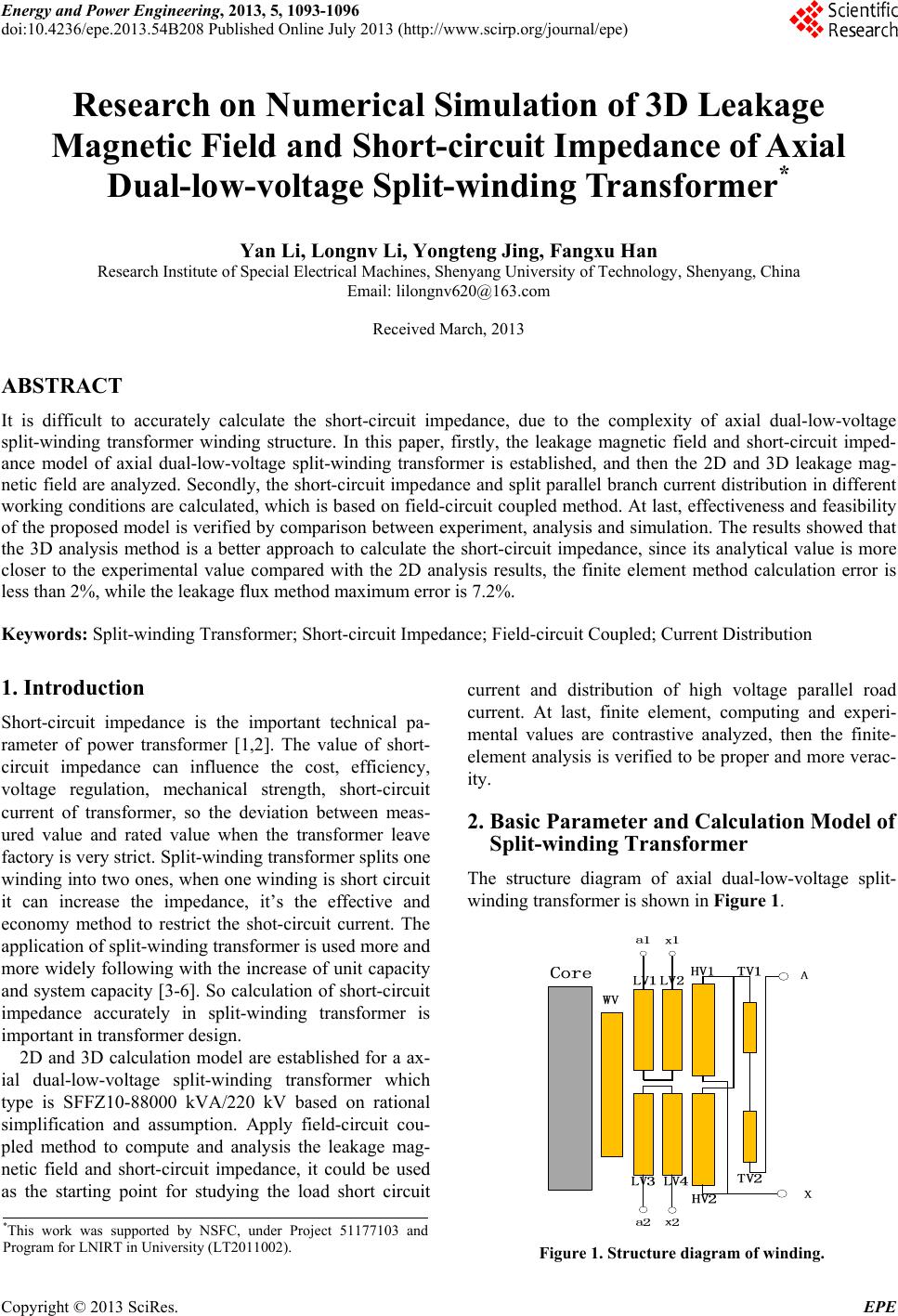 Energy and Power Engineering, 2013, 5, 1093-1096 doi:10.4236/epe.2013.54B208 Published Online July 2013 (http://www.scirp.org/journal/epe) Research on Numerical Simulation of 3D Leakage Magnetic Field and Short-circuit Impedance of Axial Dual-low-voltage Split-winding Transformer* Yan Li, Longnv Li, Yongteng Jing, Fangxu Han Research Institute of Special Electrical Machines, Shenyang University of Technology, Shenyang, China Email: [email protected] Received March, 2013 ABSTRACT It is difficult to accurately calculate the short-circuit impedance, due to the complexity of axial dual-low-voltage split-winding transformer winding structure. In this paper, firstly, the leakage magnetic field and short-circuit imped- ance model of axial dual-low-voltage split-winding transformer is established, and then the 2D and 3D leakage mag- netic field are analyzed. Secondly, th e short-circuit impedance and split parallel branch curren t distribution in different working conditions are calculated, which is based on field-circuit coupled method. At last, effectiveness and feasibility of the proposed model is verified by comparison between experiment, analysis and simulation. The results showed that the 3D analysis method is a better approach to calculate the short-circuit impedance, since its analytical value is more closer to the experimental value compared with the 2D analysis results, the finite element method calculation error is less than 2%, while the leakage flux method maximum error is 7.2%. Keywords: Split-winding Transformer; Short-circuit Impedance; Field-circuit Coupled; Current Distribution 1. Introduction Short-circuit impedance is the important technical pa- rameter of power transformer [1,2]. The value of short- circuit impedance can influence the cost, efficiency, voltage regulation, mechanical strength, short-circuit current of transformer, so the deviation between meas- ured value and rated value when the transformer leave factory is very strict. Split-winding transformer splits one winding into two ones, wh en one winding is short circuit it can increase the impedance, it’s the effective and economy method to restrict the shot-circuit current. The application of split-winding transformer is used more and more widely following with the increase of unit capacity and system capacity [3-6]. So calculation of short-circuit impedance accurately in split-winding transformer is important in transformer design. 2D and 3D calculation model are established for a ax- ial dual-low-voltage split-winding transformer which type is SFFZ10-88000 kVA/220 kV based on rational simplification and assumption. Apply field-circuit cou- pled method to compute and analysis the leakage mag- netic field and short-circuit impedance, it could be used as the starting point for studying the load short circuit current and distribution of high voltage parallel road current. At last, finite element, computing and experi- mental values are contrastive analyzed, then the finite- element analysis is verified to be proper and more verac- ity. 2. Basic Parameter and Calculation Model of Split-winding Transformer The structure diagram of axial dual-low-voltage split- winding transformer is shown in Figure 1. *This work was supported by NSFC, under Project 51177103 and Program for LN IRT in University (LT2011002) . Figure 1. Structure diagram of winding. Copyright © 2013 SciRes. EPE 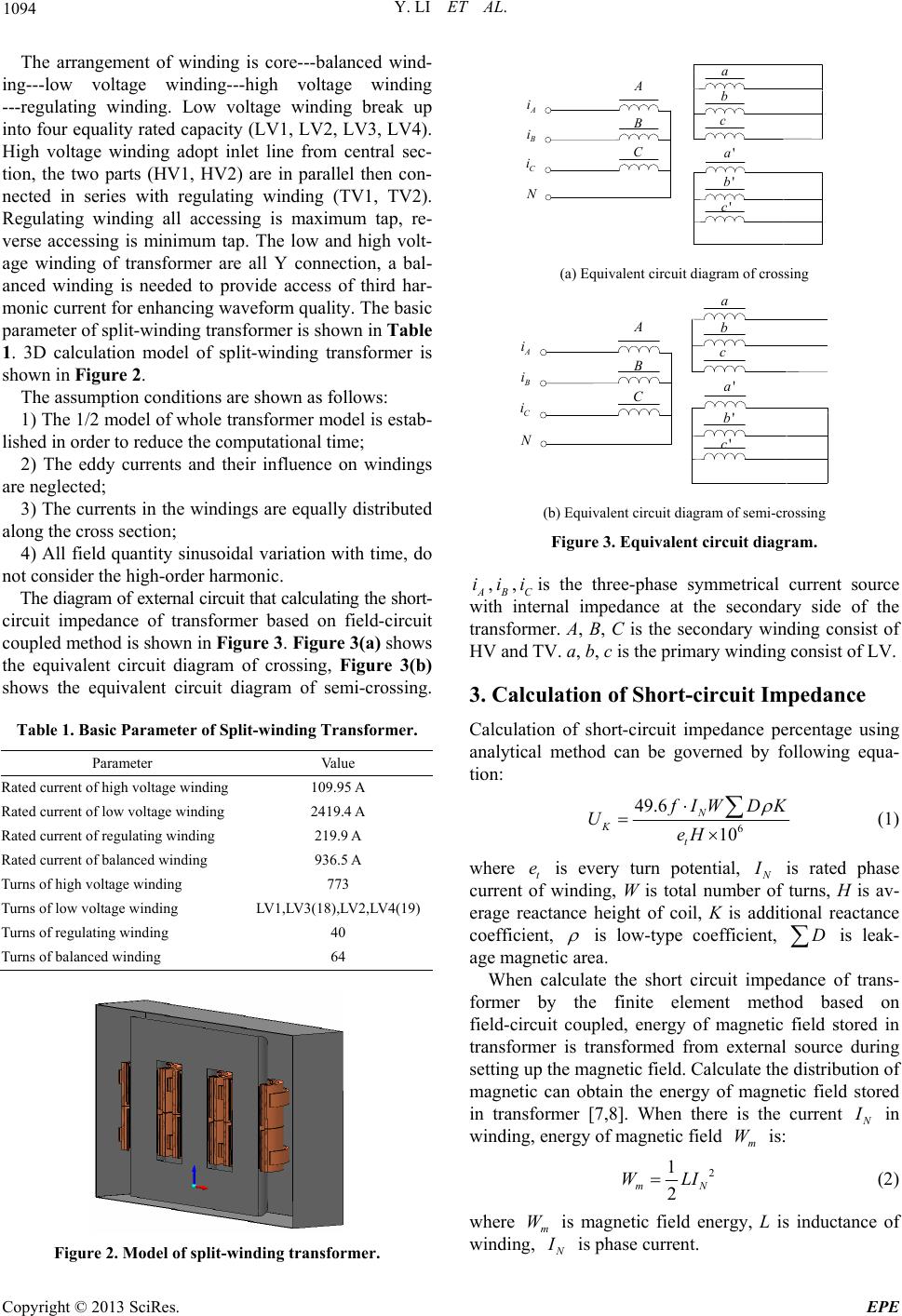 Y. LI ET AL. 1094 The arrangement of winding is core---balanced wind- ing---low voltage winding---high voltage winding ---regulating winding. Low voltage winding break up into four equality rated capacity (LV1 , LV2, LV3, LV4). High voltage winding adopt inlet line from central sec- tion, the two parts (HV1, HV2) are in parallel then con- nected in series with regulating winding (TV1, TV2). Regulating winding all accessing is maximum tap, re- verse accessing is minimum tap. The low and high volt- age winding of transformer are all Y connection, a bal- anced winding is needed to provide access of third har- monic current for enhancing waveform quality. The basic parameter of split-winding transformer is shown in Table 1. 3D calculation model of split-winding transformer is shown in Figure 2. The assumption cond itions are shown as follows: 1) The 1/2 model of whole transformer model is estab- lished in order to reduce the computational time; 2) The eddy currents and their influence on windings are neglec t ed; 3) The currents in the windings are equa lly distributed along the cross section; 4) All field quantity sinusoidal variation with time, do not consider the high-order harmonic. The diagram of external circuit that calculating the short- circuit impedance of transformer based on field-circuit coupled method is shown in Figure 3. Figure 3(a) shows the equivalent circuit diagram of crossing, Figure 3(b) shows the equivalent circuit diagram of semi-crossing. Table 1. Basic Parameter of Split-winding Transformer. Parameter Value Rated current of high voltage winding 109.95 A Rated current of low voltage winding 2419.4 A Rated current of regulating winding 219.9 A Rated current of balanced winding 936.5 A Turns of high voltage winding 773 Turns of low voltage wind in g LV1,LV3(18),LV2,LV4(19) Turns of regula ti n g w i nd i ng 40 Turns of balanced wi n d i n g 64 Figure 2. Model of split-winding transformer. A i B i C i N A B C a b c 'c 'b 'a (a) Equivalent circuit diagram of crossing A i B i C i N A B C a b c 'c 'b ' a (b) Equivalent circ u i t d i a g ram of semi-crossing Figure 3. Equivalent circuit diagram. A,i B i,Cis the three-phase symmetrical current source with internal impedance at the secondary side of the transformer. A, B, C is the secondary winding consist of HV and TV. a, b, c is the primary winding consist of LV. i 3. Calculation of Short-circuit Impedance Calculation of short-circuit impedance percentage using analytical method can be governed by following equa- tion: 6 49.6 10 N K t f IWD K UeH (1) where t is every turn potential, e N I is rated phase current of winding, W is total number of turns, H is av- erage reactance height of coil, K is additional reactance coefficient, is low-type coefficient, is leak- age magnetic area. D When calculate the short circuit impedance of trans- former by the finite element method based on field-circuit coupled, energy of magnetic field stored in transformer is transformed from external source during setting up the magnetic field. Calculate the distribution of magnetic can obtain the energy of magnetic field stored in transformer [7,8]. When there is the current N I in winding, energy of magnetic field is: m W 2 1 2 m WLIN (2) where is magnetic field energy, L is inductance of winding, m W N I is phase current. Copyright © 2013 SciRes. EPE  Y. LI ET AL. 1095 When resistive component of the short-circuit imped- ance can be ignored, the short-circuit impedance of cor- responding rated current N I is: 2 2 K mN Z LWI (3) where K Z is short-circuit impedance (leakage reac- tance), is angular frequency of power source. Percentage of short-ci rcuit impedance is shown as: 4 N m K KNN LI fW Z U Z UVA (4) Where K U is percentage of short-circuit impedance, f is frequency, VA is capacity of single phase when transformer working under rated operating condition. 4. Analysis of Calculation Results The short-circuit impedance of axial dual-low-voltage split-winding transformer is calculated and analyzed though analytical method, 2D and 3D finite element me- thod. The distribution of leakage magnetic vector when the transformer is working under crossing and semi- crossing condition are respectively shown in Figure 4(a) and Figure 4(b). The comparison of results about the short-circuit im- pedance of split-winding transformer working under dif- ferent conditions are shown in Table 2. In this table, low-up is LV1 and LV2 in the structure diagram, low- down is LV3 and LV4 in the structure diagram, Zd is the short-circuit impedance of crossing, ZB is the short-cir- cuit impedance of semi-crossing. (a) Leakage magnetic vector distribution of crossing (b) Leakage magnetic vector distribution of semi-crossing Figure 4. 3D leakage magnetic field distribution (rated tap). Table 2. Short-circuit Impedance Results of Split- winding Transformer (%). Calculation conditions Calculation MeasuredError/% Analytical 9.92 0.7 2D 9.76 0.9 Zd 3D 9.83 9.85 0.2 Analytical 18.5 0.27 2D 18.59 0.22 ZB (high/low-up) 3D 18.63 18.55 0.43 Analytical 18.5 0.16 2D 18.65 0.97 RATE D TAP ZB (high/low-down) 3D 18.63 18.47 0.87 Analytical 10.08 0.5 2D 9.96 1.2 Zd 3D 10.03 10.08 0.5 Analytical 18.87 0.53 2D 18.86 0.48 ZB (high/low-up) 3D 18.8 18.77 0.16 Analytical 18.87 1 2D 18.9 1.18 MA X TAP ZB (high/low-down) 3D 18.92 18.68 1.28 Analytical 9.61 3.3 2D 9.87 0.7 Zd 3D 10 9.94 0.6 Analytical 17.36 7.2 2D 18.87 0.85 ZB (high/low-up) 3D 18.82 18.71 0.59 Analytical 17.36 6.5 2D 18.78 1.13 MI N TAP ZB (high/low-down) 3D 18.82 18.57 1.34 Figure 5. End winding magnetic flux density distribution along circle direction. The distribution of magnetic flux density along circle direction of upper end of the winding under crossing condition is shown in Figure 5. The distribution of mag- netic flux density is uneven along the circle direction of Copyright © 2013 SciRes. EPE  Y. LI ET AL. Copyright © 2013 SciRes. EPE 1096 Table 3. Current calculation of HV parallel branch (-show phase contrast). Calculation conditions High voltage up/A High voltage down/A Zd 109.95 110.14 ZB(high/low-up) 111.02 -1.08 Rated tap ZB(high/low-down) -1.11 111.02 Zd 104.62 104.88 ZB(high/low-up) 108.62 -3.66 Max tap ZB(high/low-down) -3.67 108.62 Zd 129.13 129.67 ZB(high/low-up) 120.92 8.46 Min tap ZB(high/low-down) 8.45 120.93 winding from the figure, the magnetic flux density in the core window is larger than that out of the core window. The comparative analysis of the analytical method, 2D finite element method, 3D finite element method and measured values shows that the 3D finite element calcu- lation value is more close to the measured value. Due to short-circuit impedance is decided by the value and re- gularity of distribution of leakage magnetic field, ana- lytical method can not calculate the leakage magnetic accurately. 2D finite element method can not figure up the uneven of the distribution of magnetic field along the circle direction of winding. So the 3D finite element me- thod is the best choice when calculating short-circuit impedance. 5. Analysis of Current Distribution In this paper, the high voltage winding is connected in parallel, then series connected with regulating winding, current excitation is applied at high voltage side when calculating short-circuit impedance from Figure 1. The problem of current distribution is analyzed in different conditions, the calculation results of 3D finite element method are shown in Table 3. Table 3 shows that the high voltage parallel branch current in crossing is not much different and equal divi- sion when in the three conditions; current in semi-crossing is different and distribution uneven. The reason for this phenomenon is that: under the semi-crossing, the two low voltage winding impedances are different in the up and down two parallel branches, and the magnetic field is mutual affected. At last, a circle flowing the two low-voltage winding is emerged to counteract the imbalance of impedance. 6. Conclusions In this paper, an axial dual-low-voltage split-winding transformer is selected as the research object, calculation model of the equivalent circuit and the leakage magnetic field is established. Analytical method, 2D and 3D finite element method are used to calculate the short-circuit impedance of transformer in different conditions, then get the following conclusions: 1) The error of 3D finite element and measured values is in 2%. The maximum error of analytical method achieves 7.2%. The 3D finite element method is more accurate than the 2D one and analytical method. 2) The current distribution can be accurately obtained by 3D field-circuit coupled finite element analysis me- thod though the analysis of current distribution of high voltage parallel branch, then the precise short-circuit impedance is gained. All of these can be the reference frame in the short-circuit design of split-winding trans- former. REFERENCES [1] S. S. Wang, Y. M. Li and Y. N. Guo, “Calculation of Short-circuit Impedance for Power Transformer with Coupling FEM Method of Magnetic Field and Circuit,” High Voltage Engineering, Vol. 32, No. 11, 2006, pp. 11-14. [2] B. R. Xie, Q. F. Chen and X. S. Li, et al., “Calculation of the Short-circuit Impedance of the Transformer with Split Types of Windings Using Three-dimensional FEM,” High Voltage Engineering, Vol. 33, No. 6, 2007, pp. 97-101. [3] K. F. Qu, W. Zhao and B. Jiang Bo, et al., “3D FEM Computation of Magnetic Field of Heavy Current Trans- former with Shielding Coils,” High Voltage Apparatus, Vol. 45, No. 1, 2009, pp. 25-32. [4] P. Zhou, D. Lin and W. N. Fu, et al., “A General Simula- tion Approach for Coupled Field-circuit Problems,” IEEE Tans. on Magnetics, Vol. 42, No. 4, 2006, pp. 1051-1054. doi:10.1109/TMAG.2006.871374 [5] S. Kanerva, S. Seman and A. ArkkIio, “Inductance Model for Coupling Finite Element Analysis With Circuit Simu- lation,” IEEE Tansactions on Magnetics, Vol. 41, No. 5, 2005, pp. 1620-1623. [6] B. R. Xie, Q. F. Chen and C. H. Kang, et al., “Modeling and Impedance Parameter Design for Multi-winding Transformer Based on Combined Field-circuit Coupled Method,” Proceeding of the CSEE, Vol. 29, No. 9, 2009, pp. 104-111. [7] F. X. Han, Y. Li and X. Sun, et al ., “Calculation of Leak- age Magnetic Field and Short Circuit Impedance of Power Transformer,” Transformer, Vol. 47, No. 10, 2010, pp. 9-12. [8] J. M. Wang, J. G. Jia and L. R. Liu, et al., “Research on Numerical Simulation of Three Dimensional Leakage Magnetic Field and Short Circuit Impedance of Phase-Shifting Rectifier Transformer,” Transformer, Vol. 46, No. 4, 2009, pp. 1-5. |