

Paper Menu >>
Journal Menu >>
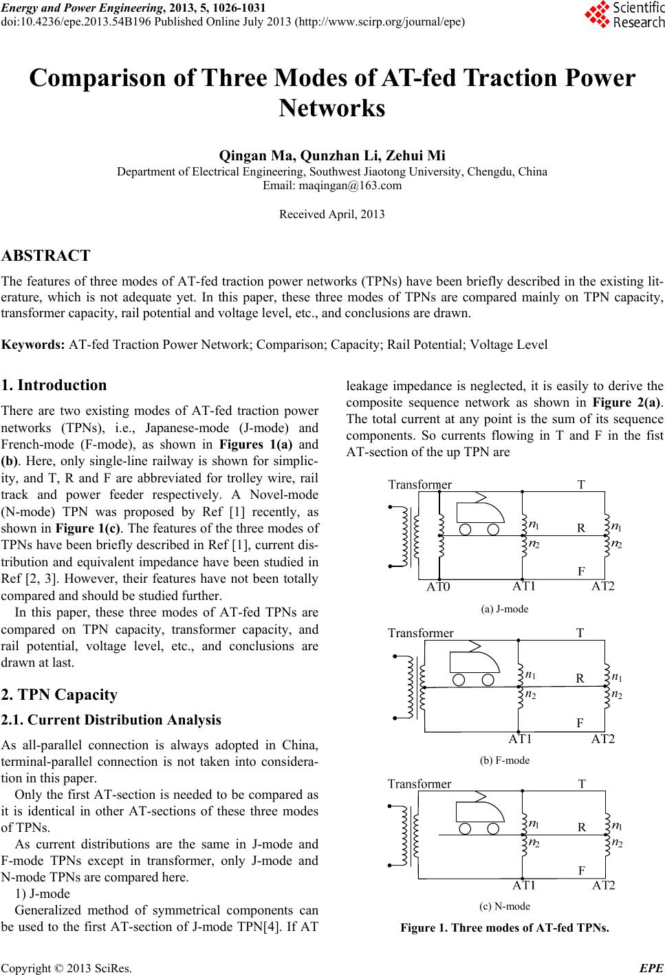 Energy and Power Engineering, 2013, 5, 1026-1031 doi:10.4236/epe.2013.54B196 Published Online July 2013 (http://www.scirp.org/journal/epe) Comparison of Three Modes of AT-fed Traction Power Networks Qingan Ma, Qunzhan Li, Zehui Mi Department of Electrical Engineering, Southwest Jiaotong University, Chengdu, China Email: [email protected] Received April, 2013 ABSTRACT The features of three modes of AT-fed traction power networks (TPNs) have been briefly described in the existing lit- erature, which is not adequate yet. In this paper, these three modes of TPNs are compared mainly on TPN capacity, transformer capacity, rail potential and voltage level, etc., and conclusions are drawn. Keywords: AT-fed Traction Power Network; Comparison; Capacity; Rail Potential; Voltage Level 1. Introduction There are two existing modes of AT-fed traction power networks (TPNs), i.e., Japanese-mode (J-mode) and French-mode (F-mode), as shown in Figures 1(a) and (b). Here, only single-line railway is shown for simplic- ity, and T, R and F are abbreviated for trolley wire, rail track and power feeder respectively. A Novel-mode (N-mode) TPN was proposed by Ref [1] recently, as shown in Figure 1(c). The features of the three modes of TPNs have been briefly described in Ref [1], current dis- tribution and equivalent impedance have been studied in Ref [2, 3]. However, their features have not been totally compared and should be studied further. In this paper, these three modes of AT-fed TPNs are compared on TPN capacity, transformer capacity, and rail potential, voltage level, etc., and conclusions are drawn at last. 2. TPN Capacity 2.1. Current Distribution Analysis As all-parallel connection is always adopted in China, terminal-parallel connection is not taken into considera- tion in this paper. Only the first AT-section is needed to be compared as it is identical in other AT-sections of these three modes of TPNs. As current distributions are the same in J-mode and F-mode TPNs except in transformer, only J-mode and N-mode TPNs are compared here. 1) J-mode Generalized method of symmetrical components can be used to the first AT-section of J-mode TPN[4]. If AT leakage impedance is neglected, it is easily to derive the composite sequence network as shown in Figure 2(a). The total current at any point is the sum of its sequence components. So currents flowing in T and F in the fist AT-section of the up TPN are (a) J-mode AT1 AT2 n1 T R F Transformer n1 n2n2 (b) F-mode (c) N-mode Figure 1. Three modes of AT-fed TPNs. Copyright © 2013 SciRes. EPE 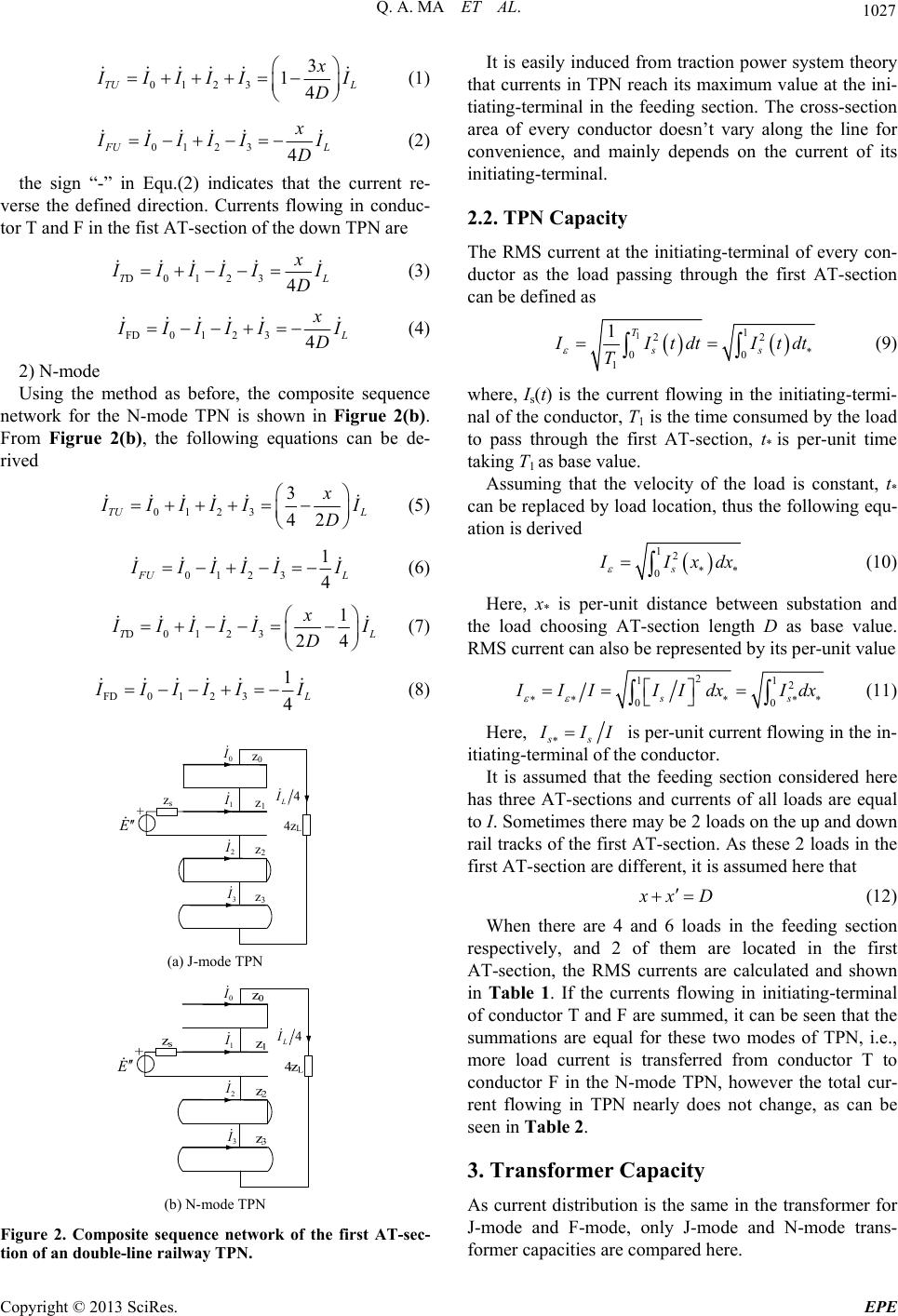 Q. A. MA ET AL. 1027 0123 3 14 TU L x I IIII I D (1) 0123 4 F U xL I IIII I D (2) the sign “-” in Equ.(2) indicates that the current re- verse the defined direction. Currents flowing in conduc- tor T and F in the fist AT-section of the down TPN are D 0123 4 T xL I IIIII D (3) FD0 1 234 L x I IIII I D (4) 2) N-mode Using the method as before, the composite sequence network for the N-mode TPN is shown in Figrue 2(b). From Figrue 2(b), the following equations can be de- rived 0123 3 42 TU L x I IIII I D (5) 01 23 1 4 F UL I IIII I (6) D 0123 1 24 T xL I IIII I D (7) FD0 1 23 1 4 L I IIII I (8) E z1 z0 4 L I + z2 z3 4zL 0 I 1 I 2 I 3 I zs (a) J-mode TPN E 4 L I 0 I 1 I 2 I 3 I (b) N-mode TPN Figure 2. Composite sequence network of the first AT-sec- tion of an double-line railway TPN. It is easily induced from traction power system theory that currents in TPN reach its maximum value at the ini- tiating-terminal in the feeding section. The cross-section area of every conductor doesn’t vary along the line for convenience, and mainly depends on the current of its initiating-terminal. 2.2. TPN Capacity The RMS current at the initiating-terminal of every con- ductor as the load passing through the first AT-section can be defined as 11 22 00 1 1T ss I ItdtItdt T (9) where, Is(t) is the current flowing in the initiating-termi- nal of the conductor, T1 is the time consumed by the load to pass through the first AT-section, t* is per-unit time taking T1 as base value. Assuming that the velocity of the load is constant, t* can be replaced by load location, thus the following equ- ation is derived 12 0s I Ixdx (10) Here, x* is per-unit distance between substation and the load choosing AT-section length D as base value. RMS current can also be represented by its per-unit value 2 12 0 ss 1 0 I IIIIdx Idx (11) Here, ss I II is per-unit current flowing in the in- itiating-terminal of the conductor. It is assumed that the feeding section considered here has three AT-sections and currents of all loads are equal to I. Sometimes there may be 2 loads on the up and down rail tracks of the first AT-section. As these 2 loads in the first AT-section are different, it is assumed here that x xD (12) When there are 4 and 6 loads in the feeding section respectively, and 2 of them are located in the first AT-section, the RMS currents are calculated and shown in Table 1. If the currents flowing in initiating-terminal of conductor T and F are summed, it can be seen that the summations are equal for these two modes of TPN, i.e., more load current is transferred from conductor T to conductor F in the N-mode TPN, however the total cur- rent flowing in TPN nearly does not change, as can be seen in Table 2. 3. Transformer Capacity As current distribution is the same in the transformer for J-mode and F-mode, only J-mode and N-mode trans- former capacities are compared here. Copyright © 2013 SciRes. EPE  Q. A. MA ET AL. 1028 Table 1. RMS current of conductor T and F (pu). J-mode N-mode Load number T F T F 4 1.283 0.764 1.041 1.0 6 1.774 1.258 1.528 1.5 Table 2. Conductors summary current in TPN. Load number J-mode N-mode 4 2.033 2.041 6 3.024 3.028 In the F-mode transformer, currents flowing in the two segments of the secondary winding are unequal. How- ever, the cross-section areas of these two sections of winding are identical in manufacturing for convenience, and they depend on the bigger one, that produced by the up load is shown as below via generalized method of symmetrical components 12 S xL I I D (13) In the same manner, the current produced by the down load is 12 S xL I I D (14) Here, x —distance between substation and the down load, the total current is derived by summing Equ.13 and 14 11 22 SL xx L I I DD I (15) Taking into account Equ.12, Equ.15 becomes 3 2 SL I I (16) If there are 4 loads in feeding section, the total current flowing in the secondary winding of traction transformer is 4 5 2 SL I I (17) If there are 6 loads, the current is 6 7 2 TL I I (18) As only positive sequence current flows in the second winding of the J-mode transformer, the total current flowing in the secondary winding is 2 L I and 3 L I for 4 or 6 loads, respectively. Let, the per-unit current flowing in the secondary winding is derived and shown in Table 3. Thus the capacity of the F-mode transformer is bigger than that of the J-mode transformer. 1 L I 4. Other Aspects In this section, three modes of TPNs are compared on rail potential, voltage level and earthling-current, etc., based on its chain circuit model [5]. Here the load is represented by constant admittance of 0.02S. It is specified in Ref [6] that the resistance of the earthling electrode in the traction substation should not exceed 0.5Ω. In high soil resistivity area, the value should not exceed 5Ω. Both 0.5Ω and 5Ω are applied in the simulation for comparison. TPN parameters are listed in Tables 4-7. Here, PW (protection wire) and GW (grounding wire) are reduced to conductor H. “U” and “D” is used for up and down TPNS respectively. 4.1. Rail Potential As current distribution is identical for J- mode and F-mode of TPNs [5], it can be induced that rail potentials are also the same. It is only needed to compare J-mode and N-mode TPNs. Table 3. Transformer capacity comparison. Load number J-mode F-mode 4 2 2.5 6 3 3.5 Table 4. Admittances of current return circuit (S/km). H U R U H D R D HU 1.655 0 -0.646 0 RU 0 0.01 0 0 Table 5. Impedances of current return circuit (Ω/km). H U R U H D R D HU 0.163+0.584i0.050+0.372i 0.049+0.317i 0.049+0.317i RU 0.050+0.372i0.117+0.801i 0.049+0.339i 0.049+0.339i Table 6. Impedances of T and F (Ω/km). T U F U T D F D TU0.135+0.646i 0.052+0.381i 0.050+0.381i 0.050+0.340i FU0.052+0.381i 0.190+0.777i 0.050+0.340i 0.050+0.317i Table 7. Mutual impedances between T, F and H, R(Ω/km). T U F U T D F D HU0.048+0.374i 0.046+0.416i 0.049+0.338i 0.049+0.315i RU0.048+0.375i 0.047+0.353i 0.049+0.358i 0.048+0.331i Copyright © 2013 SciRes. EPE 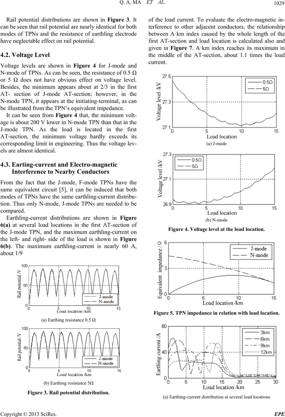 Q. A. MA ET AL. 1029 Rail potential distributions are shown in Figure 3. It can be seen that rail potential are nearly identical for both modes of TPNs and the resistance of earthling electrode have neglectable effect on rail potential. 4.2. Voltage Level Voltage levels are shown in Figure 4 for J-mode and N-mode of TPNs. As can be seen, the resistance of 0.5 Ω or 5 Ω does not have obvious effect on voltage level. Besides, the minimum appears about at 2/3 in the first AT- section of J-mode AT-section; however, in the N-mode TPN, it appears at the initiating-terminal, as can be illustrated from the TPN’s equivalent impedance. It can be seen from Figure 4 that, the minimum volt- age is about 200 V lower in N-mode TPN than that in the J-mode TPN. As the load is located in the first AT-section, the minimum voltage hardly exceeds its corresponding limit in engineering. Thus the voltage lev- els are almost identical. 4.3. Earting-current and Electro-magnetic Interference to Nearby Conductors From the fact that the J-mode, F-mode TPNs have the same equivalent circuit [5], it can be induced that both modes of TPNs have the same earthling-current distribu- tion. Thus only N-mode, J-mode TPNs are needed to be compared. Earthling-current distributions are shown in Figure 6(a) at several load locations in the first AT-section of the J-mode TPN, and the maximum earthling-current on the left- and right- side of the load is shown in Figure 6(b). The maximum earthling-current is nearly 60 A, about 1/9 (a) Earthing resistance 0.5 Ω (b) Earthing resistance 5Ω Figure 3. Rail potential distribution. of the load current. To evaluate the electro-magnetic in- terference to other adjacent conductors, the relationship between A·km index caused by the whole length of the first AT-section and load location is calculated also and given in Figure 7. A·km index reaches its maximum in the middle of the AT-section, about 1.1 times the load current. (a) J-mode (b) N-mode Figure 4. Voltage level at the load location. Figure 5. TPN impedance in relation with load location. (a) Earthing-current distribution at several load locations Copyright © 2013 SciRes. EPE 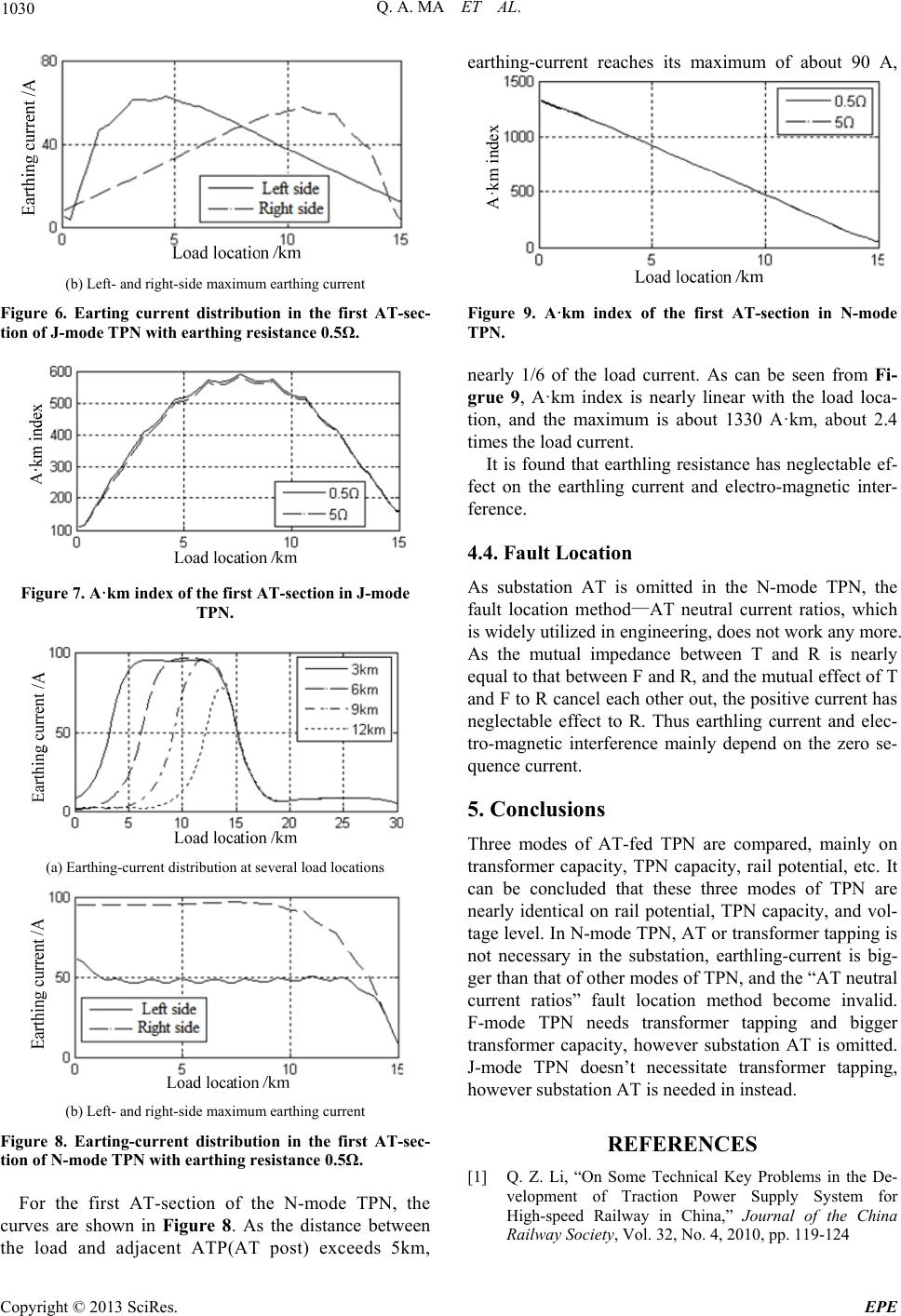 Q. A. MA ET AL. 1030 (b) Left- and right-side maximum earthing current Figure 6. Earting current distribution in the first AT-sec- tion of J-mode TPN with earthing resistance 0.5Ω. Figure 7. A·km index of the first AT-section in J-mode TPN. (a) Earthing-current distribution at several load locations (b) Left- and right-side maximum earthing current Figure 8. Earting-current distribution in the first AT-sec- tion of N-mode TPN with earthing resistance 0.5Ω. For the first AT-section of the N-mode TPN, the curves are shown in Figure 8. As the distance between the load and adjacent ATP(AT post) exceeds 5km, earthing-current reaches its maximum of about 90 A, A·km index Figure 9. A·km index of the first AT-section in N-mode TPN. nearly 1/6 of the load current. As can be seen from Fi- grue 9, A·km index is nearly linear with the load loca- tion, and the maximum is about 1330 A·km, about 2.4 times the load current. It is found that earthling resistance has neglectable ef- fect on the earthling current and electro-magnetic inter- ference. 4.4. Fault Location As substation AT is omitted in the N-mode TPN, the fault location method—AT neutral current ratios, which is widely utilized in engineering, does not work any more. As the mutual impedance between T and R is nearly equal to that between F and R, and the mutual effect of T and F to R cancel each other out, the positive current has neglectable effect to R. Thus earthling current and elec- tro-magnetic interference mainly depend on the zero se- quence current. 5. Conclusions Three modes of AT-fed TPN are compared, mainly on transformer capacity, TPN capacity, rail potential, etc. It can be concluded that these three modes of TPN are nearly identical on rail potential, TPN capacity, and vol- tage level. In N-mode TPN, AT or transformer tapping is not necessary in the substation, earthling-current is big- ger than that of other modes of TPN, and the “AT neutral current ratios” fault location method become invalid. F-mode TPN needs transformer tapping and bigger transformer capacity, however substation AT is omitted. J-mode TPN doesn’t necessitate transformer tapping, however substation AT is needed in instead. REFERENCES [1] Q. Z. Li, “On Some Technical Key Problems in the De- velopment of Traction Power Supply System for High-speed Railway in China,” Journal of the China Railway Society, Vol. 32, No. 4, 2010, pp. 119-124 Copyright © 2013 SciRes. EPE  Q. A. MA ET AL. Copyright © 2013 SciRes. EPE 1031 [2] A. W. Li, “Optimal at Power Supply and Transformer Wiring Type,” master’s Thesis, Southwest Jiaotong Uni- versity, Chengdu, 2010 [3] G. Li and G. S Lin, “Short Circuit Impedance Analysis for Novel AT Power Traction Network,” Asia-Pacific Power and Energy Engineering Conference of IEEE Power & Energy Society (PES), Shanghai, 26-28 March 2012, pp. 1-5 [4] F. H. Wang, “A Generalized Method of Symmetrical Components and Its Applications,” Journal of Southwest Jiaotong University, Vol. 4, No.1, 1981, pp. 1-12. doi:10.1007/s11771-997-0018-z [5] M. L. Wu, “Study on Electrical Parameters and Mathe- matical Model of Traction Power Supply Systems,” Ph.D. Thesis, Beijing Jiaotong University, Beijing, 2006 [6] TB10009-2005, Design Code of Railway Electric Trac- tion Feeding. |