

Paper Menu >>
Journal Menu >>
 Energy and Power Engineering, 2013, 5, 986-991 doi:10.4236/epe.2013.54B189 Published Online July 2013 (http://www.scirp.org/journal/epe) Reactive Power Reserve Improvement Using Power Systems Inherent Structural Characteristics Tajudeen H. Sikiru1, Adisa A. Jimoh2, Yskandar Hamam3, John T. Agee2, Roger Ceschi4 1Department of Electrical Engineering, Tshwane University of Technology, South Africa and LISV of UVSQ, France 2Department of Electrical Engineering, Tshwane University of Technology, South Africa 3ESIEE Paris, France and FSATI at Tshwane University of Technology, South Africa 4LISV of UVSQ and ESME Sudria, France Email: [email protected], [email protected], [email protected], [email protected], [email protected] Received January, 2013 ABSTRACT This paper considers the use of the inherent structural characteristics of power system networks for improving the reac- tive power reserve margins for both topologically weak and strong networks. The inherent structural characteristics of the network are derived from the Schur complement of the partitioned Y-admittance matrix using circuit theory repre- sentations. Results show that topologically strong networks, operating close to the upper voltage limit could be made to increase their loadability margin by locating reactive power compensators close to generator sources, whereas topo- logically weak (ill conditioned) networks could be made to operate within the feasible operating limits by locating reac- tive power compensators on buses farther from generator sources. Keywords: Power System Networks Inherent Characteristics; Reactive Power Reserve Margin; Loadability Margin; Schur Complement 1. Introduction Transmission network plays a critical role in power sys- tems operations. Its role in ensuring reliable operations of power systems was acknowledged after post-mortem analysis of major blackouts in many advanced countries [1]. However, the concept of using transmission net- works inherent structural characteristics to resolve power systems operational issues has not been fully considered. Transmission networks traditionally serve the purpose of transporting power from generating stations to load cen- tres. The amount of power that could be supplied from generating stations to load centres and the routes for the power flows depend on the transmission network struc- tural interconnections [2]. The structural interconnections between the power system nodes define the power sys- tem inherent structural characteristics [3]. These charac- teristics are governed by the value of line impedances and how they are interconnected. Line impedances con- sist of resistive and reactive components. The reactive components account for the reactive power presence on the network, which majorly affect the network operating voltages and the amount of transferable active power a transmission network can support [4]. Transmission net- works with excess reactive power are in general topo- logically strong networks and have network bus voltages that are very high beyond the nominal limit. On the other hand, topologically weak (ill conditioned) networks, which are in deficit of reactive power, have low voltages below the nominal limit [5]. Therefore, there is the need to balance the amount of reactive power in a network against the desired voltage operating limits [6]. However, due to scarce resources, the difficulty of securing rights of way and environmental issues, power system networks are forced to operate within tight technical constraints. The effect in recent times is the total blackouts caused by voltage collapsed experienced by many matured power system networks around the world [1]. So far, the approaches used to address reactive power reserve mainly range from the linear programming tech- nique to nonlinear programming techniques [7-13]. However, the challenge for these optimisation techniques is the nonlinear, non-convex nature of the problem for- mulation [14]. Due to the non-convex nature of the problem, many optimisation techniques could easily be trapped in local minima [11]. Secondly, ill conditioned networks could lead to suboptimal solutions because of the need to locate fictitious reactive power compensators first, to achieve convergence of load flow before the loadability of the network can be properly addressed [15]. Thirdly, the large sizes of practical networks could be a challenge when the nonlinearity of the problem formulation is fully considered, since large solution variables would need to Copyright © 2013 SciRes. EPE  T. H. SIKIRU ET AL. 987 be generated and may present memory storage issues [13]. Finally, different buses on the network affect the network operations differently because of the nonlinear- ity of the network parameters [16]. Because of these challenges, there is therefore, the need to reconsider the fundamental circuit theory properties of network, in or- der to identify its inherent structural characteristics that could be used to achieve better reactive power manage- ment. This paper focuses on the inherent structural charac- teristics of power system networks as a solution guide to the issue of reactive power reserve management. For the remainder of the paper, section II presents a brief over- view of reactive power reserve management tools, sec- tion III discusses the inherent structural characteristics of networks and section IV presents a case study and result discussion. Finally, section V concludes the paper and highlights the major findings. 2. Techniques for Assessing Reactive Power Reserve Margin The purpose of adequate reactive power in a network is to ensure operation of the network at both normal and stressed conditions. The stressed condition consists of lost of major lines, transformers, generators or a situation where load gradually increase until the network cannot support such load demand corresponding to the nose curve point D in Figure 1, referred to as voltage collapse point [15]. A power system with operating voltage at point A is ill conditioned, because, it is operating below the nominal voltage limit. This is caused by the unavail- ability of sufficient reactive power in the network, hence, load flow may not converge for such networks [17]. It is necessary to move the operating point to between points B and C for which load flow will converge [15]. Figure 1 shows that as the network voltages move more towards point C, the amount of extra power demand it can sup- port increases (i.e. increased loadability margin) until beyond point C where it is infeasible to operate the net- work. The relationship between voltages and network loadability is nonlinear. The amount of load demand the network can support before voltage collapse is referred to as its maximum loadability margin. The loadability mar- gin is a function of reactive power reserve in the network [18]. The techniques used for assessing the maximum load- ability of networks are continuous power flow (CPF) technique and optimal power flow-direct method (OPF- DM) or mathematical optimisation techniques [14,18,19]. The difference between the two techniques is that in the latter, to ensure adequate reactive power margin, system security variables to be maintained within limits must be defined, hence constituting an indirect approach to secu- rity assessment of the network [19]. max V min V Figure 1. Power-voltage curve. The CPF technique uses a modified power flow whose loading margin can be expressed as 0c (1) where c is maximum loading at the critical point and 0 is the current or base loading margin. As changes with load increase, it relationship with variation in generation and load pattern are 0GG G PP KP S (2) 0 L L PP P D (3) 0 L LL QQ KP D (4) where 0G is the generation base level, 0 P L P and 0 L Q are the base level of active and reactive respectively, G K represents distributed slack bus and L K represents loads with constant power factor. S and P D P repre- sent generation and load directions respectively [19]. In the case of optimisation techniques, the maximum loadability can be expressed as [14] ,, ,, max LGG VVQ (5) Subject to ,, , ,0 GiLiPLGijij PPGVVGB (6) ,, , ,0 GiLiqL Gijij QQGVVGB (7) min max GiGi Gi PPP (8) min max GiGi Gi QQQ (9) min max iii VVV (10) where 1in Q, Gi is the active power generation at bus , Gi is the reactive power generation at bus i, G is the generator bus voltage magnitude, P i V L V is the load bus voltage magnitude, is the bus voltage phase angles, L i is the active power demand at bus i, P L i is the reactive power demand at bus i, ij is the conduc- tance of line and ij is the susceptance of line [19]. Equations (6) and (7) are the power balance equa- tions of the network, while Equations (8) - (10) are the Q G ij Bij Copyright © 2013 SciRes. EPE  T. H. SIKIRU ET AL. 988 inequalities that must be satisfied for the network to op- erate between points B and C of Figure 1. For topologi- cally weak (ill conditioned) networks, convergence of load flow may not hold since the network is operating around point A [17]. Other approaches besides those presented in this section are necessary to identify suitable locations for reactive compensators for such networks [20]. On the other hand, topological strong networks have voltages that are between points B and C of Figure 1; however, if the loadability of the network is to be in- creased then suitable locations for reactive power com- pensators are required. In order to satisfy these objectives, the inherent structural characteristics of network which may serve as a guide in selecting suitable reaction power compensators locations is presented in the next section. 3. Inherent S tructural Characteristic s of Networks The fundamental circuit theorem law applicable to power system networks can be written as I YV (11) where I is current, Y is network admittance and V is voltage. Suppose that the Y-admittance matrix is partitioned as GG GL LG LL YY YYY (12) where GG is the generator-generator coupling in the system admittance matrix with dimension G YG , GL is the generator-load coupling in the system admittance matrix with dimension , Y GL L G is the load-genera- tor coupling in the system admittance matrix with di- mension and YLL is the load-load coupling in the system admittance matrix with dimension . G and L are the number of generator and load buses in the net- work respectively. Y LG LL We can express (11) as GG GLG LG LL G L L YY I V YY I V (13) where G I is injected generator bus currents, L I is injected load bus currents, G is generator bus complex voltages and V L V is load bus complex voltages. Since GG , the leading submatrix in (12) is non-sin- gular, the Schur complement [21,22] of in Y is Y GG Y 1 L L LGGGGL YYY YY (14) The determinant of the Y-admittance matrix based on Schur complement formula [21] is 1 detdet det GGLLLG GG GL YY YYYY (15) In compact form (15) is expressed as detdetdet GG LL YYC (16) where 1 L LLL LGGGGL CYYYY and represents the equivalent admittance of the network with all influences associated to generators eliminated. The importance of matrix L L in relation to power system network is clearer from the algebraic manipula- tion of (13) which gives C 1 LLLLLGG VCIWI (17) where 1 L GLGG WYY G The right hand side of (17) shows that matrix L L is inversely related to the network bus voltages. Combining this fact with the determinant relationship of this matrix with the entire network structure presented in equation (16), it shows that matrix C L L holds essential informa- tion about the network structure. In order to identify these inherent structural characteristics contained in ma- trix C L L, eigenvalue decomposition technique [23] is applied as C 1 n L L i CMRM mm iii (18) where M is a orthonormal matrix with eigenvectors , while i m i are the eigenvalues. Since the inverse of matrix L L exist due to the non-singularity of , the generalized inverse of matrix C GG Y L L C is 11 1 nii LL ii mm CMRM (19) Substituting Equation (19) into Equation (17) gives 1 T nii LL ii vm VIW LGG I (20) The buses associated with the smallest eigenvalues in matrix L L would have the most effect on the network bus voltages as mathematically expressed in Equation (20), due to the reciprocal relationship between eigen- values and the load voltages. From power system per- spective, the smallest eigenvalue C 0 n based on a predefined precision level, will occur when the network buses are electrically far from one another, because of the shortage of adequate reactive element within the network structure. The corresponding left eigenvectors (matrix M) in this case will have column vectors with constant values, indicating non-participation between the network buses. This indicates a topologically weak (ill conditioned) network [5]. As previously discussed, topo- logically weak network have low voltages [5]. Buses associated with the smallest eigenvalues indicate where reactive power support are required [20]. Hence, to im- prove the overall voltage profile these buses are suitable locations for reactive power compensators [24]. Copyright © 2013 SciRes. EPE  T. H. SIKIRU ET AL. 989 On the hand, when the smallest eigenvalue is 0 n based on a predefined precision level, there is adequate reactive element presence in the network structure. The degree of sufficiency of the reactive elements dependent on the participation between the network buses observ- able from the eigenvectors of matrix M. Networks that exhibit such characteristics are topologically strong net- works [5]. As already mentioned, such networks have adequate voltages. In order to improve the loadability margin for such networks, generators should be pre- vented from reaching their reactive power limits by add- ing reactive power compensators close to the generators. Buses associated with the largest eigenvalues are suitable locations for achieving this objective, since they are the ones closest to the generator buses. The next section il- lustrates this concept with a case study. 4. Case Study and Discussion of Results The test network is a 40 bus Southwest networks shown in Figure 2. The voltage profile of this test network without any reactive power compensator is shown in Figure 3. The purpose of adding reactive power com- pensators is mainly for increasing the loadability margin of this test network [14]. The smallest eigenvalue for this network is 0.0045 (in absolute value) from the application of equation (19). A set of five suitable locations for installing reactive power compensators associated with the largest eigenvalues for improving the loadability margin of the test network are presented in Table 1. In order to ascertain the effectiveness of these loca- tions on reactive power reserve margin, comparison with locations obtained using multi start-Benders decomposi- tion technique published in [14] for the same network is used in this paper. Continuous power flow (CPF) reactive power assessment technique implemented in Power System Figure 2. Southwe st England 40 bus ne twork. Analysis Toolbox (PSAT) with generation and load di- rections set was used to determine the maximum load- ability margin of the test network. The maximum load- ability for both approaches are shown in Table 2 using a Static Var Compensator (SVC) of . 0.04 pu The power-voltage curves for the lowest voltage of each approach are shown in Figure 4 for the maximum loadability corresponding to installation of five SVCs. The proposed approach improves the network load- ability margin better compared to the multi start-Benders decomposition technique as shown in Table 2 and Fig- ure 4 respectively. This is because the propose approach seeks to locate reactive power compensators close to generators, in order to prevent the generators from Figure 3. Voltage profile of Southwest 40 bus networ k. Table 1. Suitable locations for reactive power compensa- tors. S/NLargest eigenvalues Bus number 1 16.4309 9 2 9.9136 11 3 9.3788 10 4 8.2647 12 5 7.3916 2 Table 2. Comparison of maximum loadability. Proposed Approach Multi start-Benders decomposition Number of SVCsBus number (p.u) Bus number (p.u) 1 9 1.143429 1.1237 2 9,11 1.193929,30 1.174 3 9,11,10 1.244529,30,32 1.1978 4 9,11,10,121.293429,30,32,31 1.2045 5 9,11,10,12,21.340529,30,32,31,28 1.2119 Base (No SVC) Maximum loadability (λ) = 1.0909 p.u. Copyright © 2013 SciRes. EPE 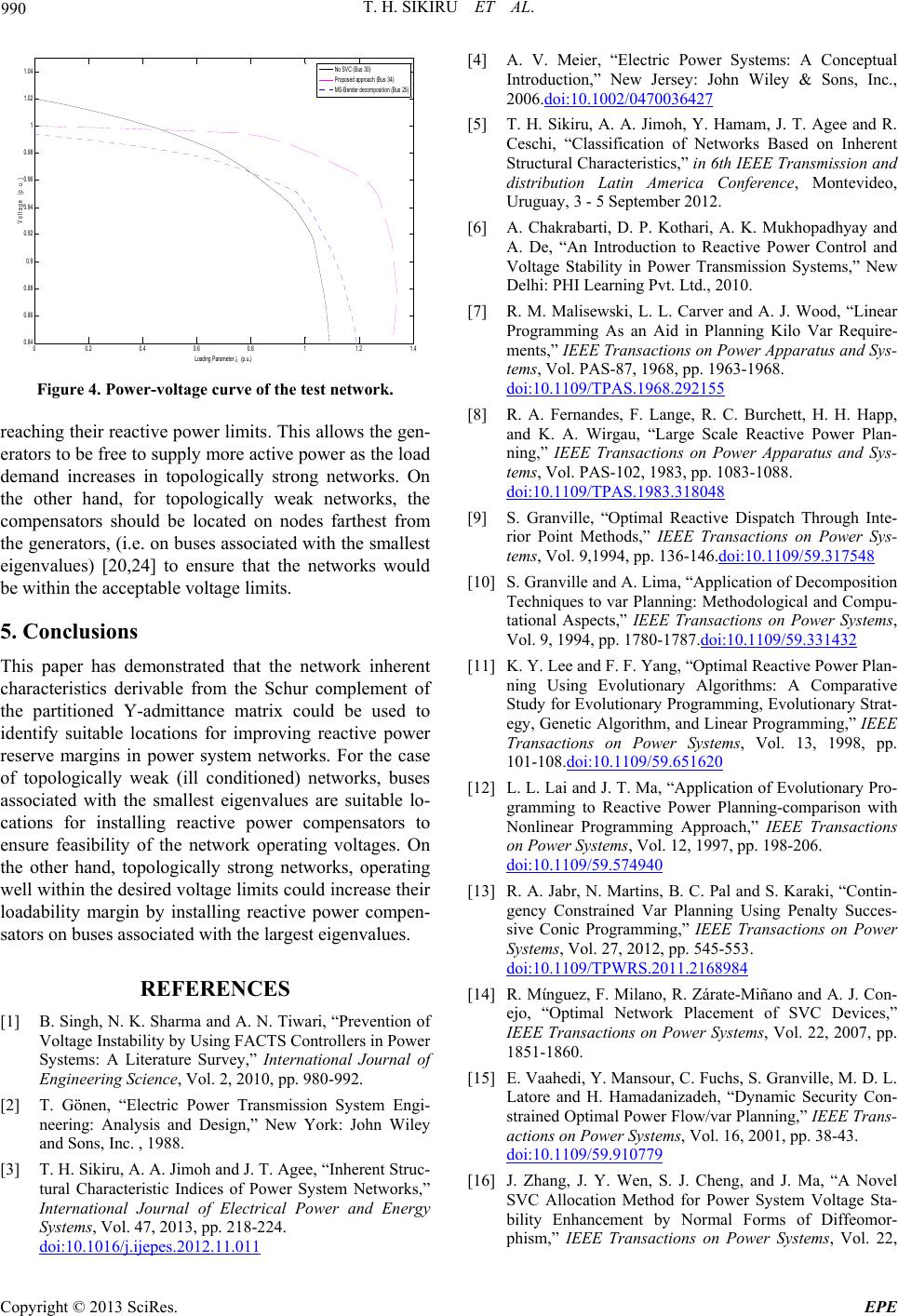 T. H. SIKIRU ET AL. 990 00.2 0.4 0.6 0.8 11.2 1.4 0.8 4 0.8 6 0.8 8 0.9 0.9 2 0.9 4 0.9 6 0.9 8 1 1.0 2 1.0 4 Loading Parameter (p.u.) Voltage (p.u.) No SVC (Bus 30) Pro po sed ap proa c h (B u s 34) MS-B e nd er deco m po s it i o n (Bus 25) Figure 4. Power-voltage curve of the test network. reaching their reactive power limits. This allows the gen- erators to be free to supply more active power as the load demand increases in topologically strong networks. On the other hand, for topologically weak networks, the compensators should be located on nodes farthest from the generators, (i.e. on buses associated with the smallest eigenvalues) [20,24] to ensure that the networks would be within the acceptable voltage limits. 5. Conclusions This paper has demonstrated that the network inherent characteristics derivable from the Schur complement of the partitioned Y-admittance matrix could be used to identify suitable locations for improving reactive power reserve margins in power system networks. For the case of topologically weak (ill conditioned) networks, buses associated with the smallest eigenvalues are suitable lo- cations for installing reactive power compensators to ensure feasibility of the network operating voltages. On the other hand, topologically strong networks, operating well within the desired voltage limits could increase their loadability margin by installing reactive power compen- sators on buses associated with the largest eigenvalues. REFERENCES [1] B. Singh, N. K. Sharma and A. N. Tiwari, “Prevention of Voltage Instability by Using FACTS Controllers in Power Systems: A Literature Survey,” International Journal of Engineering Science, Vol. 2, 2010, pp. 980-992. [2] T. Gönen, “Electric Power Transmission System Engi- neering: Analysis and Design,” New York: John Wiley and Sons, Inc. , 1988. [3] T. H. Sikiru, A. A. Jimoh and J. T. Agee, “Inherent Struc- tural Characteristic Indices of Power System Networks,” International Journal of Electrical Power and Energy Systems, Vol. 47, 2013, pp. 218-224. doi:10.1016/j.ijepes.2012.11.011 [4] A. V. Meier, “Electric Power Systems: A Conceptual Introduction,” New Jersey: John Wiley & Sons, Inc., 2006.doi:10.1002/0470036427 [5] T. H. Sikiru, A. A. Jimoh, Y. Hamam, J. T. Agee and R. Ceschi, “Classification of Networks Based on Inherent Structural Characteristics,” in 6th IEEE Transmission and distribution Latin America Conference, Montevideo, Uruguay, 3 - 5 September 2012. [6] A. Chakrabarti, D. P. Kothari, A. K. Mukhopadhyay and A. De, “An Introduction to Reactive Power Control and Voltage Stability in Power Transmission Systems,” New Delhi: PHI Learning Pvt. Ltd., 2010. [7] R. M. Malisewski, L. L. Carver and A. J. Wood, “Linear Programming As an Aid in Planning Kilo Var Require- ments,” IEEE Transactions on Power Apparatus and Sys- tems, Vol. PAS-87, 1968, pp. 1963-1968. doi:10.1109/TPAS.1968.292155 [8] R. A. Fernandes, F. Lange, R. C. Burchett, H. H. Happ, and K. A. Wirgau, “Large Scale Reactive Power Plan- ning,” IEEE Transactions on Power Apparatus and Sys- tems, Vol. PAS-102, 1983, pp. 1083-1088. doi:10.1109/TPAS.1983.318048 [9] S. Granville, “Optimal Reactive Dispatch Through Inte- rior Point Methods,” IEEE Transactions on Power Sys- tems, Vol. 9,1994, pp. 136-146.doi:10.1109/59.317548 [10] S. Granville and A. Lima, “Application of Decomposition Techniques to var Planning: Methodological and Compu- tational Aspects,” IEEE Transactions on Power Systems, Vol. 9, 1994, pp. 1780-1787.doi:10.1109/59.331432 [11] K. Y. Lee and F. F. Yang, “Optimal Reactive Power Plan- ning Using Evolutionary Algorithms: A Comparative Study for Evolutionary Programming, Evolutionary Strat- egy, Genetic Algorithm, and Linear Programming,” IEEE Transactions on Power Systems, Vol. 13, 1998, pp. 101-108.doi:10.1109/59.651620 [12] L. L. Lai and J. T. Ma, “Application of Evolutionary Pro- gramming to Reactive Power Planning-comparison with Nonlinear Programming Approach,” IEEE Transactions on Power Systems, Vol. 12, 1997, pp. 198-206. doi:10.1109/59.574940 [13] R. A. Jabr, N. Martins, B. C. Pal and S. Karaki, “Contin- gency Constrained Var Planning Using Penalty Succes- sive Conic Programming,” IEEE Transactions on Power Systems, Vol. 27, 2012, pp. 545-553. doi:10.1109/TPWRS.2011.2168984 [14] R. Mίnguez, F. Milano, R. Zárate-Miñano and A. J. Con- ejo, “Optimal Network Placement of SVC Devices,” IEEE Transactions on Power Systems, Vol. 22, 2007, pp. 1851-1860. [15] E. Vaahedi, Y. Mansour, C. Fuchs, S. Granville, M. D. L. Latore and H. Hamadanizadeh, “Dynamic Security Con- strained Optimal Power Flow/var Planning,” IEEE Trans- actions on Power Systems, Vol. 16, 2001, pp. 38-43. doi:10.1109/59.910779 [16] J. Zhang, J. Y. Wen, S. J. Cheng, and J. Ma, “A Novel SVC Allocation Method for Power System Voltage Sta- bility Enhancement by Normal Forms of Diffeomor- phism,” IEEE Transactions on Power Systems, Vol. 22, Copyright © 2013 SciRes. EPE  T. H. SIKIRU ET AL. Copyright © 2013 SciRes. EPE 991 2007, pp. 1819-825. doi:10.1109/TPWRS.2007.907538 [17] F. Milano, “Continuous Newton’s Method for Power Flow Analysis,” IEEE Transactions on Power Systems, Vol. 24, 2009, pp. 50-57. doi:10.1109/TPWRS.2008.2004820 [18] V. Ajjarapu and C. Christy, “The Continuation Power Flow: A Tool for Steady State Voltage Stability Analy- sis,” IEEE Transactions on Power Systems, Vol. 7, 1992, pp. 416-423. doi:10.1109/59.141737 [19] J. R. Avalos Muñoz, “Analysis and Application of Opti- misation Techniques to Power System Security and Elec- tricity Markets,” PhD University of Waterloo, 2009. [20] T. H. Sikiru, A. A. Jimoh, Y. Hamam, J. T. Agee and R. Ceschi, “Voltage Profile Improvement Based on Network Structural Characteristics,” in 6th IEEE Transmission and Distribution Latin America Conference, Montevideo, Uruguay, 3 - 5 September 2012. [21] R. W. Cottle, “Manifestations of the Schur Complement,” Linear Algebra and Its Applications,” Vol. 8, 1974, pp. 189-211. doi:10.1016/0024-3795(74)90066-4 [22] D. Carlson, “What are Schur Complements, Anyway?," Linear Algebra and Its Applications, Vol. 74, 1986, pp. 257-275. doi:10.1016/0024-3795(86)90127-8 [23] G. H. Golub and C. F. Van Loan, “Matrix Computations,” Oxford: North Oxford Academic, 1983. [24] T. H. Sikiru, A. A. Jimoh and J. T. Agee, “Optimal Loca- tion of Network Devices Using a Novel Inherent Network Topology Based Technique,” in IEEE AFRICON 2011, Livingstone, 13-15 September 2011, pp. 1-4. |