

Paper Menu >>
Journal Menu >>
 Energy and Power Engineering, 2013, 5, 941-944 doi:10.4236/epe.2013.54B180 Published Online July 2013 (http://www.scirp.org/journal/epe) New Method of Measuring the Positive-sequence Capacitance of T-connection Transmission Lines Yuansen Zhang1, Demin Cui1, Qingtao Cao1, Yongqiang Chai1, Peng Liu1, Xiaobo Li 1, Zhijian Hu2, Chuanqi Li2, Chengxue Zhang2 1Dezhou Power Supply Company, Shandong Electric Power Group Co., Dezhou, China 2School of Electrical Engineering, Wuhan University, Wuhan, China Email: [email protected] Received February, 2013 ABSTRACT A novel method of measuring the positive-sequence capacitance of T-connection transmission lines is proposed. The mathematical model of the new method is explained in detail. In order to obtain enough independent equations, three independent operation modes of T-connection transmission lines during the line measurement are introduced. The digi- tal simulation results and field measurement results are show n. The simulation and measurement results hav e validated that the new method can meet the needs of measuring the positive-sequence capacitance of T-connection transmission lines. This method has been implemented in the newly developed measurement instrument. Keywords: T-connection Transmission Lines; Line Parameter; Positive-sequence Capacitance; Measurement 1. Introduction With the rapid development of power systems, line cor- ridors become more and more crowed. In order to reduce synthetic cost of the line construction and limited objec- tive conditions, T-connection transmission lines are al- ways applied in HV/EHV. The reliable operation of power systems depends on the correct operation of re- laying protection devices [1]. It is well known that the computation for parameters of T-connection transmission lines is derived from Carson formula [2]. It is influenced by many practical factors, such as the resistance of earth, the equivalent depth of the lines and, etc. So the parameters should be practically measured rather than theoretically calculated. There are many related literatures discussing about measuring the impedance parameters of T-connection transmission lines [3-5]. The capacitance parameters are always ignored. But the capacitance is very important for transmission line protection. When it exceeds certain length, because the numerical value of capacity current is big, the current flow on both sides of the lines and phase relation will change according with the increase of ca- pacity current value. Especially, when load current and short-circuit current are small, it can lead to the malop- eration of high frequency protection [6, 7]. If we use the traditional method to measure the capacitance of T-con- nection transmission lines, it can only calculate parallel values of three branches. When the parameters of three branches are different, the traditional method no longer works. So, new measurement method needs to be found out for the positive-sequence capacitance of T-connec- tion transmission lines. In this paper, a new method of measuring positive- sequence capacitance of T-connection lines is proposed. The method has been applied to the newly developed measurement instrument. 2. The Theory of the Measurement Method Usually, the length of T-connection transmission lines is less than 50 km. So it can use the lumped parameter model. Each branch can be equivalent to T-form circuit. The lumped parameter model of T-form equivalent cir- cuit is shown in Figure 1. When the length and impedance of transmission lines are known, the susceptance can be calculated. Three phases end is opening circuit, , the susceptance y is as follows, 20I 1 I 2 I /2z/2z 1 U 2 U ygjb Figure 1. The lumped parameter model of T-form equiva- lent circuit. Copyright © 2013 SciRes. EPE 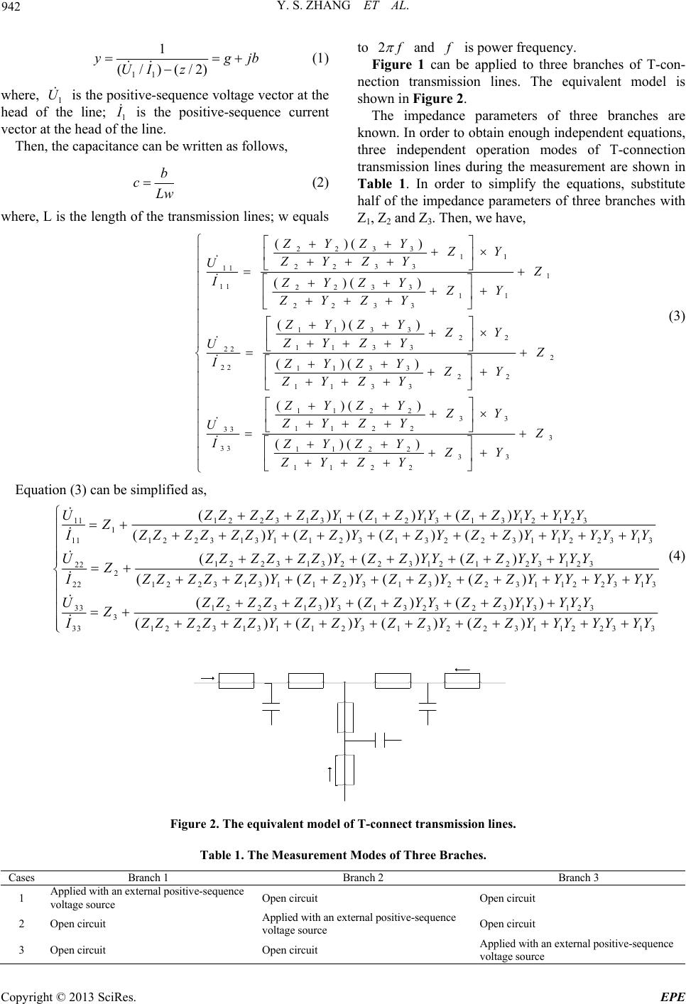 Y. S. ZHANG ET AL. 942 11 1 (/)(/2) yg UIz jb (1) where, 1 is the positive-sequence voltage vector at the head of the line; 1 U I is the positive-sequence current vector at the head of the line. Then, the capacitance can be written as follows, b cLw (2) where, L is the length of the transmission lines; w equals to 2 f and f is power frequency. Figure 1 can be applied to three branches of T-con- nection transmission lines. The equivalent model is shown in Figure 2. The impedance parameters of three branches are known. In order to obtain enough independent equations, three independent operation modes of T-connection transmission lines during the measurement are shown in Table 1. In order to simplify the equations, substitute half of the impedance parameters of three branches with Z1, Z2 and Z3. Then, w e h ave, 2233 11 22 33 11 1 11 2233 11 22 33 113 322 113 3 22 2 22 113 322 113 3 112 2 11 33 33 ()() ()() ()( ) ()( ) ()( ) ZYZY ZY ZYZY U Z IZYZY ZY ZYZY ZYZY ZY ZYZY U Z IZYZY ZY ZYZY ZYZ Y ZY U I 33 22 3 112 233 112 2 ()( ) ZY ZY Z ZYZ YZY ZYZY (3) Equation (3) can be simplified as, 122313 112 1313 12123 11 1 11122313 112313223 1122313 122313223 121223123 22 2 221 2231 3 ()()() ()()()() ()()() ( ZZZZZZ YZZYYZZ YYYYY UZ I ZZZZZZ YZZ YZZ YZZYYYYYYY ZZ ZZZZYZ ZYYZZYYYYY UZ IZZZZZZ 1123132 23112231 331223133132 3231312 3 3 33122313112313223 1122313 )( )( )() ()()()) ()()()() YZZYZZ YZZ YYYYYYY UZZZZZZY ZZYY ZZYYYYY Z 3 I ZZZZZZ YZZ YZZ YZZ YYYYYYY (4) Figure 2. The equivalent model of T-connect transmission lines. Table 1. The Measurement Modes of Three Braches. Cases Branch 1 Branch 2 Branch 3 1 Applied with an external positive-sequence voltage source Open circuit Open circuit 2 Open circuit Applied with an external positive-sequence voltage source Open circuit 3 Open circuit Open circuit Applied with an external positive-sequence voltage source Copyright © 2013 SciRes. EPE 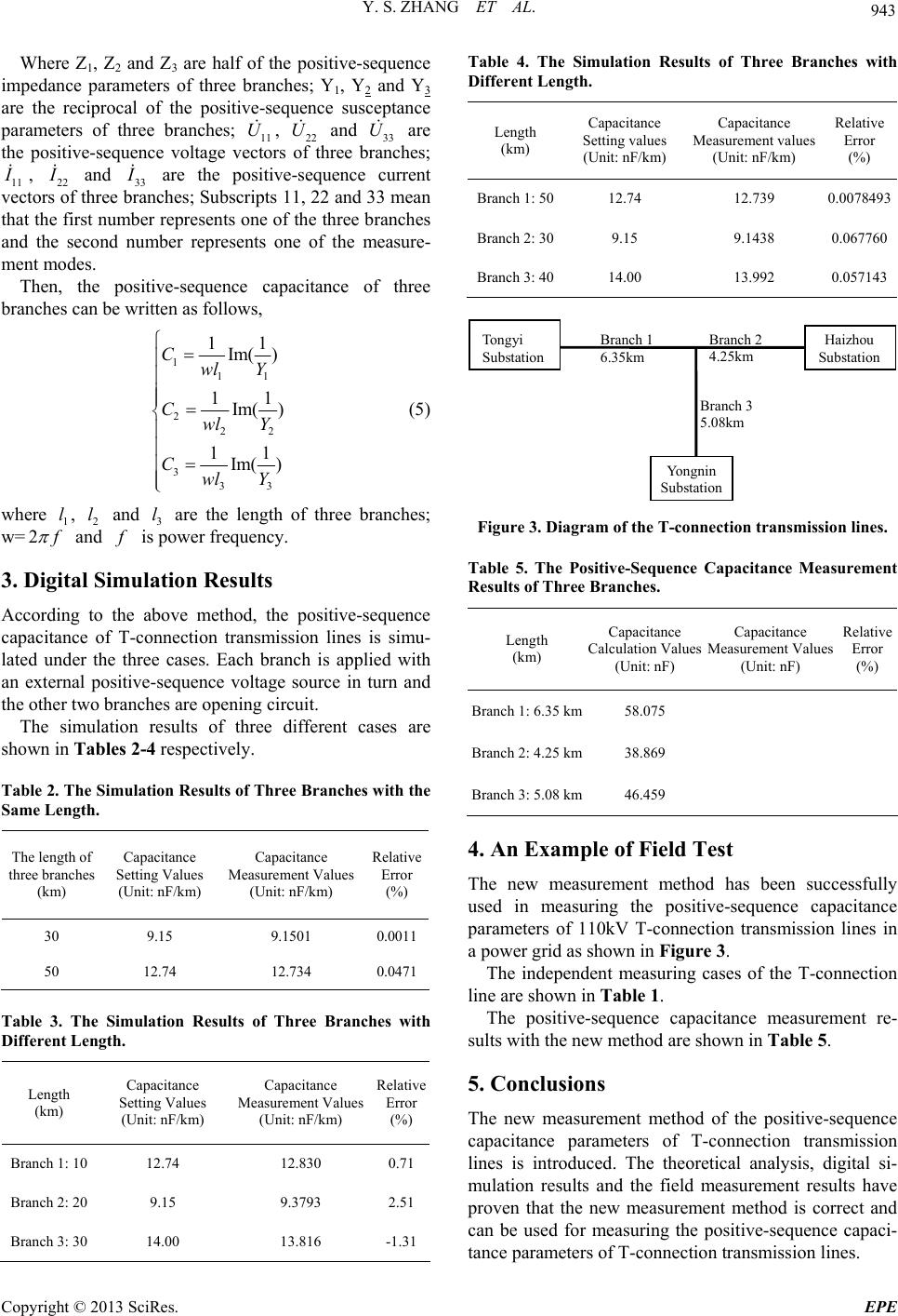 Y. S. ZHANG ET AL. 943 Where Z1, Z2 and Z3 are half of the positive-sequence impedance parameters of three branches; Y1, Y2 and Y3 are the reciprocal of the positive-sequence susceptance parameters of three branches; 11 U, 22 and 33 U are the positive-sequence voltage vectors of three branches; 11 U I , 22 I and 33 I are the positive-sequence current vectors of three branches; Subscripts 11, 22 and 33 mean that th e first number represen ts one of the three br anches and the second number represents one of the measure- ment modes. Then, the positive-sequence capacitance of three branches can be written as follows, 111 222 333 11 Im( ) 11 Im( ) 11 Im( ) Cwl Y Cwl Y Cwl Y (5) where , 2 and 3 l are the length of three branches; w= 1 l l 2 f and f is power f requency. 3. Digital Simulation Results According to the above method, the positive-sequence capacitance of T-connection transmission lines is simu- lated under the three cases. Each branch is applied with an external positive-sequence voltage source in turn and the other two branches are opening circuit. The simulation results of three different cases are shown in Tables 2-4 respectively. Table 2. The Simulation Results of Three Branches with the Same Length. The length of three branches (km) Capacitance Setting Values (Unit: nF/km) Capacitance Measurement Values (Unit: nF/km) Relative Error (%) 30 9.15 9.1501 0.0011 50 12.74 12.734 0.0471 Table 3. The Simulation Results of Three Branches with Different Length. Length (km) Capacitance Setting Values (Unit: nF/km) Capacitance Measurement Values (Unit: nF/km) Relative Error (%) Branch 1: 10 12. 74 12.830 0.71 Branch 2: 20 9.15 9.3793 2.51 Branch 3: 30 14. 0 0 13.816 -1.31 Table 4. The Simulation Results of Three Branches with Different Length. Length (km) Capacitance Setting values (Unit: nF/km) Capacitance Measurement values (Unit: nF/km) Relative Error (%) Branch 1: 5012.74 12.739 0.0078493 Branch 2: 309.15 9.1438 0. 067760 Branch 3: 4014.00 13.992 0. 057143 Tongyi Substation Haizhou Substation Yongnin Substation Branch 1 6.35km Branch 2 4.25km Branch 3 5.08km Figure 3. Diagram of the T-connection transmission lines. Table 5. The Positive-Sequence Capacitance Measurement Results of Three Branches. Length (km) Capacitance Calculation Values (Unit: nF) Capacitance Measurement Values (Unit: nF) Relative Error (%) Branch 1: 6.35 km58.075 Branch 2: 4.25 km38.869 Branch 3: 5.08 km46.459 4. An Example of Field Test The new measurement method has been successfully used in measuring the positive-sequence capacitance parameters of 110kV T-connection transmission lines in a power grid as shown in Figure 3. The independent measuring cases of the T-connection line are shown in Table 1. The positive-sequence capacitance measurement re- sults with the new method are shown in Table 5. 5. Conclusions The new measurement method of the positive-sequence capacitance parameters of T-connection transmission lines is introduced. The theoretical analysis, digital si- mulation results and the field measurement results have proven that the new measurement method is correct and can be used for measuring the positive-sequence capaci- tance parameters of T-connection transmission lines. Copyright © 2013 SciRes. EPE  Y. S. ZHANG ET AL. 944 6. Acknowledgements This work was financially supported by the Ph.D. Pro- grams Foundation of Ministry of Education of China (20110141110032). REFERENCES [1] Z. Hu and Y. Chen, “New Method of Live Line Measur- ing the Inductance Parameters of Transmission Lines Based on GPS Technology,” IEEE Transactions on Power Delivery, Vol. 23, No. 3, 2008, pp. 1288-2195. doi:10.1109/TPWRD.2007.916235 [2] J. R. Carson, “Wave Propagation in Overhead Wires with Ground Return,” Bell Syst. Tech. J., Vol. 5, 1926, pp. 539-556. [3] X. Xiong, C. Zhang and Z. Hu, “Live Line Measurement to the Zero Sequence Impedance Parameters of Multi-terminal Transmission Lines,” Power System Pro- tection and Control, Vol. 38, No. 15, 2010, pp. 65-68, 2010. [4] L. Fang and Z. Hu. “New Method of Live Line Measur- ing the Parameters of T-connection Transmission Lines with Mutual Inductance and Its Engineering Applica- tion,”Power System Technology, Vol. 34, No. 4, 2010, pp. 204-208. [5] Z. Hu. J. Fan, M. Chen and Z. Xu, “Live Line Measure- ment to the Inductance Parameters of T-connection Transmission Lines with Mutual Inductance,” Proceed- ings of the IEEE PES GM 2009, July 26-30, 2009, Cal- gary, Alberta, Canada. [6] J. Suonan, J. Gu, X. Xue, D. Liu and Z. Jiao, “Distance Protection Based on Frequency-domain Compensation Algorithm,” Automation of Electric Power Systems, Vol. 31, No. 23, 2007, pp. 57-60, 68. [7] Z. Liang, B. Li, F. Lu, P. Li and Z. Yang, “Susceptance Measurement Method at Header Point of Transmission Line,” Journal of North China Electric Power University, Vol. 28, No. 1, 2001, pp. 6-9. Copyright © 2013 SciRes. EPE |