

Paper Menu >>
Journal Menu >>
 Energy and Power Engineering, 2013, 5, 932-936 doi:10.4236/epe.2013.54B178 Published Online July 2013 (http://www.scirp.org/journal/epe) Fault current Characterization Based on Fuzzy Algorithm for DOCR Application Luly Susilo, J.C. Gu, S.K. Huang Electrical Engineering Department, National Taiwan University of Science and Technology. Email: [email protected] Received January, 2013 ABSTRACT Penetration of distribution generation (DG) into power system might disturb the existing fault diagnosis system. The detection of fault, fault classification, and random changes of direction of fault current cannot always be monitored and determined via on-line by conventional fault diagnosis system due to DG penetration. In this paper, a fault current cha- racterization which based on fuzzy logic algorithm (FLA) is proposed. Fault detection, fault classification, and fault current direction are extracted after processing the measurement result of three-phase line current. The ability of fault current characterization based on FLA is reflected in directional overcurrent relay (DOCR) model. The proposed DOCR model has been validated in microgrid test system simulation in Matlab environment. The simulation result showed accurate result for different fault location and type. The proposed DOCR model can operate as common protection de- vice (PD) unit as well as unit to improve the effectiveness of existing fault diagnosis system when DG is present. Keywords: Fault Current Characterization; Fuzzy Logic Algorithm; DOCR; Distributed Generation 1. Introduction Penetration of DG that concentrated closer to customer side can improve the efficiency of electric power deliv- ery. In the contrary, multi-source power system scheme as result of penetration of DG both in radial and ring power system might produce bi-directional power flow as well as fault current. The fault current may be in for- ward or reverse direction, and this will change rapidly depends on system requirement. It is inevitable; however, existing fault diagnosis system based on radial scheme with focusing only on single source can be no effective anymore. In conventional fault diagnosis system, after obtaining information operation status of protection de- vice (PD) during/after fault event, then the information will be matched with table database in SCADA. Dis- patcher will locate the fault section as soon as possible according to diagnosis result [1]. One aim of this work is to improve effectiveness of fault diagnosis system; PD will send its operating status to SCADA as well as the fault current characteristic information. Furthermore, dispatcher not only can locate the faulted section, but also accurately determine fault source and decide appro- priate action in advance. Sample of analog signal of line current will be proc- essed in Digital Fourier Transform (DFT) module. Mag- nitude of phase line current, positive sequence current and zero sequence current as well as angle of positive sequence current will be taking into fuzzification input, from fuzzy interference system (FIS) that already con- structed before, the membership value will be generated after comparing the input and membership function. Then from defuzzification process will decide the rela- tionship of all input line current with related fault char- acterization information. Many publications already pre- sented concept regarding fault detection, fault classifica- tion, and fault current direction which based on various intelligence control approaches (Wavelet, Neural Net- work, and FLA) [2,4,7,8]. Unfortunately, none of them clearly provided a complete concept fault characteriza- tion through a single approach. In this work, this solution is addressed. In part II, elaboration of FLA for fault characterization is provided in detail and systematic. The proposed microgrid test system as well as the DOCR and its control model in Matlab environment are shown in part III. Next part, brief discussion about simulation re- sult is conducted before closing by conclusion part. 2. Fuzzy logic algorithm (FLA) for fault current characterization The nature form of fault current characterization problem is not including complex mathematical expression. FLA is preferably to be implemented since this algorithm is simple and not involve any complex computation. Major procedures in this work are shown in Figure 1. Copyright © 2013 SciRes. EPE 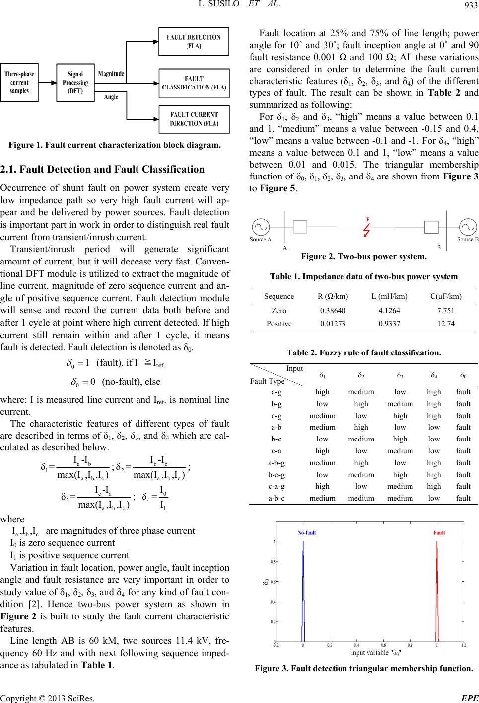 L. SUSILO ET AL. 933 Figure 1. Fault current characterization block diagram. 2.1. Fault Detection and Fault Classification Occurrence of shunt fault on power system create very low impedance path so very high fault current will ap- pear and be delivered by power sources. Fault detection is important part in work in order to distinguish real fault current from transient/inrush current. Transient/inrush period will generate significant amount of current, but it will decease very fast. Conven- tional DFT module is utilized to extract the magnitude of line current, magnitude of zero sequence current and an- gle of positive sequence current. Fault detection module will sense and record the current data both before and after 1 cycle at point where high current detected. If high current still remain within and after 1 cycle, it means fault is detected. Fault detection is denoted as δ0. 01 (fault), if I ≧Iref. 00 (no-fault), else where: I is measured line current and Iref. is nominal line current. The characteristic features of different types of fault are described in terms of δ1, δ2, δ3, and δ4 which are cal- culated as described below. ab 1 abc I-I δ=max(I,I,I) ;bc 2 abc I-I δ=max(I,I,I); ca 3 abc I-I δ=max(I,I,I) ; 0 4 1 I δ=I where abc I0 is zero sequence current I,I,I are magnitudes of three phase current I1 is positive sequence current Variation in fault location, power angle, fault inception angle and fault resistance are very important in order to study value of δ1, δ2, δ3, and δ4 for any kind of fault con- dition [2]. Hence two-bus power system as shown in Figure 2 is built to study the fault current characteristic features. Line length AB is 60 kM, two sources 11.4 kV, fre- quency 60 Hz and with next following sequence imped- ance as tabulated in Table 1. Fault location at 25% and 75% of line length; power angle for 10˚ and 30˚; fault inception angle at 0˚ and 90 fault resistance 0.001 Ω and 100 Ω; All these variations are considered in order to determine the fault current characteristic features (δ1, δ2, δ3, and δ4) of the different types of fault. The result can be shown in Table 2 and summarized as following: For δ1, δ2 and δ3, “high” means a value between 0.1 and 1, “medium” means a value between -0.15 and 0.4, “low” means a value between -0.1 and -1. For δ4, “high” means a value between 0.1 and 1, “low” means a value between 0.01 and 0.015. The triangular membership function of δ0, δ1, δ2, δ3, and δ4 are shown from Figure 3 to Figure 5. Figure 2. Two-bus power system. Table 1. Impedance data of two-bus power system Sequence R (Ω/km) L (mH/km) C(μF/km) Zero 0.38640 4.1264 7.751 Positive 0.01273 0.9337 12.74 Table 2. Fuzzy rule of fault classification. Input Fault Type δ1 δ2 δ3 δ4 δ0 a-g high medium low highfault b-g low high medium highfault c-g mediumlow high highfault a-b mediumhigh low low fault b-c low medium high low fault c-a high low medium low fault a-b-g mediumhigh low highfault b-c-g low medium high highfault c-a-g high low medium highfault a-b-c mediummedium medium low fault Figure 3. Fault detection triangular membership function. Copyright © 2013 SciRes. EPE 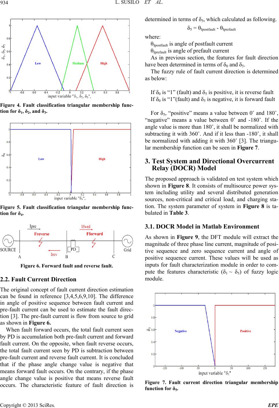 L. SUSILO ET AL. 934 Figure 4. Fault classification triangular membership func- tion for δ1, δ2, and δ3. Figure 5. Fault classification triangular membership func- tion for δ4. Figure 6. Forward fault and reverse fault. 2.2. Fault Current Direction The original concept of fault current direction estimation can be found in reference [3,4,5,6,9,10]. The difference in angle of positive sequence between fault current and pre-fault current can be used to estimate the fault direc- tion [3]. The pre-fault current is flow from source to grid as shown in Figure 6. When fault forward occurs, the total fault current seen by PD is accumulation both pre-fault current and forward fault current. On the opposite, when fault reverse occurs, the total fault current seen by PD is subtraction between pre-fault current and reverse fault current. It is concluded that if the phase angle change value is negative that means forward fault occurs. On the contrary, if the phase angle change value is positive that means reverse fault occurs. The characteristic feature of fault direction is determined in terms of δ5, which calculated as following. δ5 = θIpostfault - θIprefault where: θIpostfault is angle of postfault current θIprefault is angle of prefault current As in previous section, the features for fault direction have been determined in terms of δ0 and δ5. The fuzzy rule of fault current direction is determined as below: If δ0 is “1” (fault) and δ5 is positive, it is reverse fault If δ0 is “1”(fault) and δ5 is negative, it is forward fault For δ5, “positive” means a value between 0˚ and 180˚, “negative” means a value between 0˚ and -180˚. If the angle value is more than 180˚, it shall be normalized with subtracting it with 360˚. And if it less than -180˚, it shall be normalized with adding it with 360˚ [3]. The triangu- lar membership function can be seen in Figure 7. 3. Test System and Directional Overcurrent Relay (DOCR) Model The proposed approach is validated on test system which shown in Figure 8. It consists of multisource power sys- tem including utility and several distributed generation sources, non-critical and critical load, and charging sta- tion. The system parameter of system in Figure 8 is ta- bulated in Table 3. 3.1. DOCR Model in Matlab Environment As shown in Figure 9, the DFT module will extract the magnitude of three phase line current, magnitude of posi- tive sequence and zero sequence current and angle of positive sequence current. These values will be used as inputs for fault characterization module in order to com- pute the features characteristic (δ1 ~ δ5) of fuzzy logic module. Figure 7. Fault current direction triangular membership function for δ5. Copyright © 2013 SciRes. EPE 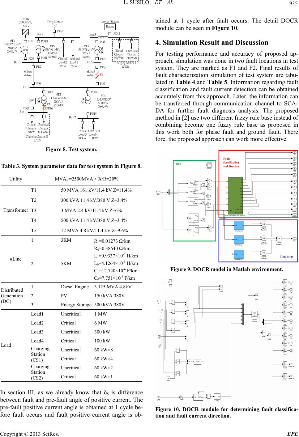 L. SUSILO ET AL. 935 Figure 8. Test system. Table 3. System parameter data for test system in Figure 8. Utility MVAsc=2500MVA,X/R=20% T1 50 MVA 161 kV/11.4 kV Z=11.4% T2 300 kVA 11.4 kV/380 V Z=3.4% T3 3 MVA 2.4 kV/11.4 kV Z=6% T4 500 kVA 11.4 kV/380 V Z=3.4% Transformer T5 12 MVA 4.8 kV/11.4 kV Z=9.6% 1 3KM #Line 2 5KM R1=0.01273 Ω/km R0=0.38640 Ω/km L1=0.9337×10⁻³ H/km L0=4.1264×10⁻³ H/km C1=12.740×10⁻⁶ F/km C0=7.751×10⁻⁶ F/km 1 Diesel Engine 3.125 MVA 4.8kV 2 PV 150 kVA 380V Distributed Generation (DG) 3 Energy Storage 500 kVA 380V Load1 Uncritical 1 MW Load2 Critical 6 MW Load3 Uncritical 300 kW Load4 Critical 100 kW Uncritical 60 kW×8 Charging Station (CS1) Critical 60 kW×4 Uncritical 60 kW×2 Load Charging Station (CS2) Critical 60 kW×1 In section III, as we already know that δ5 is difference between fault and pre-fault angle of positive current. The pre-fault positive current angle is obtained at 1 cycle be- fore fault occurs and fault positive current angle is ob- tained at 1 cycle after fault occurs. The detail DOCR module can be seen in Figure 10. 4. Simulation Result and Discussion For testing performance and accuracy of proposed ap- proach, simulation was done in two fault locations in test system. They are marked as F1 and F2. Final results of fault characterization simulation of test system are tabu- lated in Table 4 and Table 5. Information regarding fault classification and fault current detection can be obtained accurately from this approach. Later, the information can be transferred through communication channel to SCA- DA for further fault diagnosis analysis. The proposed method in [2] use two different fuzzy rule base instead of combining become one fuzzy rule base as proposed in this work both for phase fault and ground fault. There fore, the proposed approach can work more effective. Figure 9. DOCR model in Matlab environment. Figure 10. DOCR module for determining fault classifica- tion and fault current direction. Copyright © 2013 SciRes. EPE 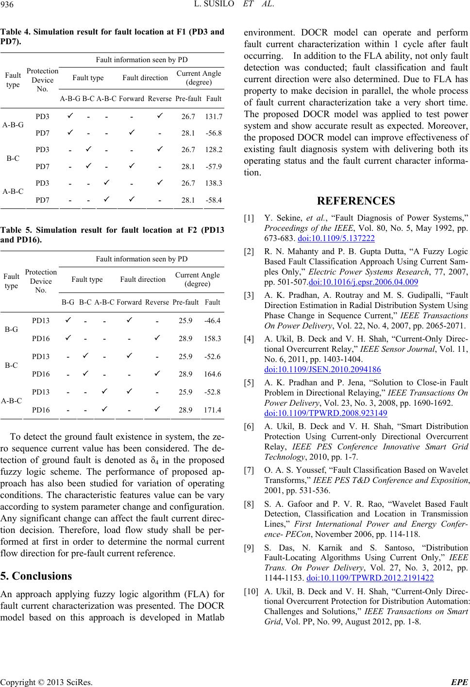 L. SUSILO ET AL. Copyright © 2013 SciRes. EPE 936 Table 4. Simulation result for fault location at F1 (PD3 and PD7). Fault information seen by PD Fault type Fault direction Current Angle (degree) Fault type Protection Device No. A-B-G B-C A-B-CForward Reverse Pre-faultFault PD3 - - - 26.7 131.7 A-B-G PD7 - - - 28.1 -56.8 PD3 - - - 26.7 128.2 B-C PD7 - - - 28.1 -57.9 PD3 - - - 26.7 138.3 A-B-C PD7 - - - 28.1 -58.4 Table 5. Simulation result for fault location at F2 (PD13 and PD16). Fault information seen by PD Fault type Fault direction Current Angle (degree) Fault type Protection Device No. B-G B-C A-B-C Forward Reverse Pre-faultFault PD13 - - - 25.9 -46.4 B-G PD16 - - - 28.9 158.3 PD13 - - - 25.9 -52.6 B-C PD16 - - - 28.9 164.6 PD13 - - - 25.9 -52.8 A-B-C PD16 - - - 28.9 171.4 To detect the ground fault existence in system, the ze- ro sequence current value has been considered. The de- tection of ground fault is denoted as δ4 in the proposed fuzzy logic scheme. The performance of proposed ap- proach has also been studied for variation of operating conditions. The characteristic features value can be vary according to system parameter change and configuration. Any significant change can affect the fault current direc- tion decision. Therefore, load flow study shall be per- formed at first in order to determine the normal current flow direction for pre-fault current reference. 5. Conclusions An approach applying fuzzy logic algorithm (FLA) for fault current characterization was presented. The DOCR model based on this approach is developed in Matlab environment. DOCR model can operate and perform fault current characterization within 1 cycle after fault occurring. In addition to the FLA ability, not only fault detection was conducted; fault classification and fault current direction were also determined. Due to FLA has property to make decision in parallel, the whole process of fault current characterization take a very short time. The proposed DOCR model was applied to test power system and show accurate result as expected. Moreover, the proposed DOCR model can improve effectiveness of existing fault diagnosis system with delivering both its operating status and the fault current character informa- tion. REFERENCES [1] Y. Sekine, et al., “Fault Diagnosis of Power Systems,” Proceedings of the IEEE, Vol. 80, No. 5, May 1992, pp. 673-683. doi:10.1109/5.137222 [2] R. N. Mahanty and P. B. Gupta Dutta, “A Fuzzy Logic Based Fault Classification Approach Using Current Sam- ples Only,” Electric Power Systems Research, 77, 2007, pp. 501-507.doi:10.1016/j.epsr.2006.04.009 [3] A. K. Pradhan, A. Routray and M. S. Gudipalli, “Fault Direction Estimation in Radial Distribution System Using Phase Change in Sequence Current,” IEEE Transactions On Power Delivery, Vol. 22, No. 4, 2007, pp. 2065-2071. [4] A. Ukil, B. Deck and V. H. Shah, “Current-Only Direc- tional Overcurrent Relay,” IEEE Sensor Journal, Vol. 11, No. 6, 2011, pp. 1403-1404. doi:10.1109/JSEN.2010.2094186 [5] A. K. Pradhan and P. Jena, “Solution to Close-in Fault Problem in Directional Relaying,” IEEE Transactions On Power Delivery, Vol. 23, No. 3, 2008, pp. 1690-1692. doi:10.1109/TPWRD.2008.923149 [6] A. Ukil, B. Deck and V. H. Shah, “Smart Distribution Protection Using Current-only Directional Overcurrent Relay, IEEE PES Conference Innovative Smart Grid Technology, 2010, pp. 1-7. [7] O. A. S. Youssef, “Fault Classification Based on Wavelet Transforms,” IEEE PES T&D Conference and Exposition, 2001, pp. 531-536. [8] S. A. Gafoor and P. V. R. Rao, “Wavelet Based Fault Detection, Classification and Location in Transmission Lines,” First International Power and Energy Confer- ence- PECon, November 2006, pp. 114-118. [9] S. Das, N. Karnik and S. Santoso, “Distribution Fault-Locating Algorithms Using Current Only,” IEEE Trans. On Power Delivery, Vol. 27, No. 3, 2012, pp. 1144-1153. doi:10.1109/TPWRD.2012.2191422 [10] A. Ukil, B. Deck and V. H. Shah, “Current-Only Direc- tional Overcurrent Protection for Distribution Automation: Challenges and Solutions,” IEEE Transactions on Smart Grid, Vol. PP, No. 99, August 2012, pp. 1-8. |