

Paper Menu >>
Journal Menu >>
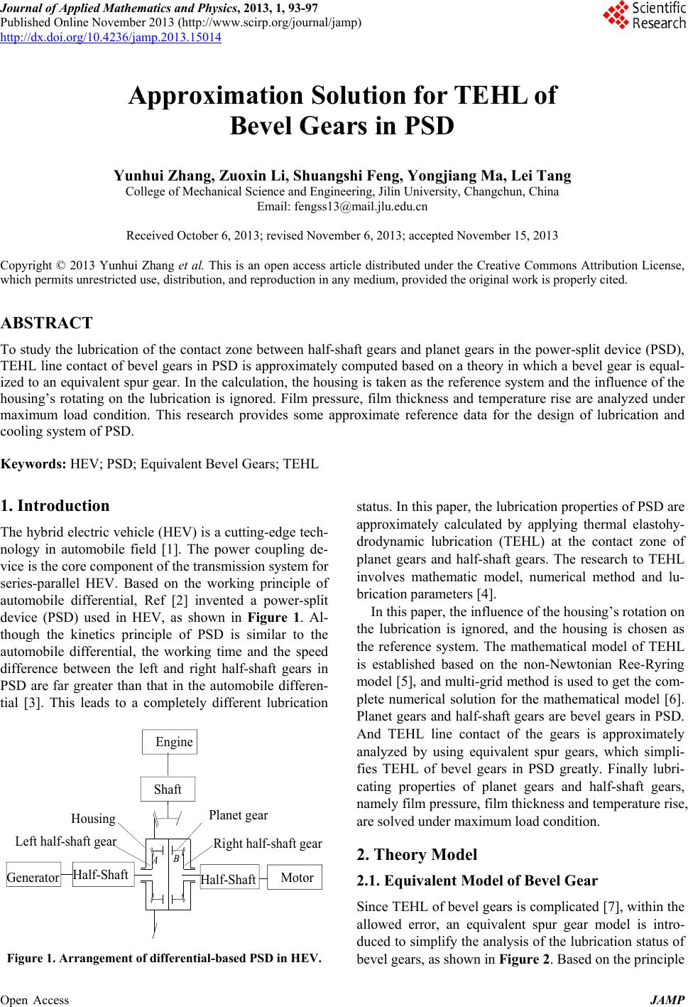 Journal of Applied Mathematics and Physics, 2013, 1, 93-97 Published Online November 2013 (http://www.scirp.org/journal/jamp) http://dx.doi.org/10.4236/jamp.2013.15014 Open Access JAMP Approximation Solution for TEHL of Bevel Gears in PSD Yunhui Zhang, Zuoxin Li, Shuangshi Feng, Yongjiang Ma, Lei Tang College of Mechanical Science and Engineering, Jilin University, Changchun, China Email: [email protected] Received October 6, 2013; revised November 6, 2013; accepted November 15, 2013 Copyright © 2013 Yunhui Zhang et al. This is an open access article distributed under the Creative Commons Attribution License, which permits unrestricted use, distribution, and reproduction in any medium, provided the original work is properly cited. ABSTRACT To study the lubrication of the contact zone between half-shaft gears and planet gears in the power-split device (PSD), TEHL line contact of bevel gears in PSD is approximately computed based on a theory in which a bevel gear is equal- ized to an equivalent spur gear. In the calculation, the housing is taken as the reference system and the influence of the housing’s rotating on the lubrication is ignored. Film pressure, film thickness and temperature rise are analyzed under maximum load condition. This research provides some approximate reference data for the design of lubrication and cooling system of PSD. Keywords: HEV; PSD; Equivalent Bevel Gears; TEHL 1. Introduction The hybrid electric vehicle (HEV) is a cutting-edge tech- nology in automobile field [1]. The power coupling de- vice is the core component of the transmission system for series-parallel HEV. Based on the working principle of automobile differential, Ref [2] invented a power-split device (PSD) used in HEV, as shown in Figure 1. Al- though the kinetics principle of PSD is similar to the automobile differential, the working time and the speed difference between the left and right half-shaft gears in PSD are far greater than that in the automobile differen- tial [3]. This leads to a completely different lubrication Engine Shaft Half-Shaft Generator Half-Shaft Motor Right half-shaft gear Planet gear Left half-shaft gear Housing A B Figure 1. Arrangement of differential-based PSD in HEV. status. In this paper, the lubrication properties of PSD are approximately calculated by applying thermal elastohy- drodynamic lubrication (TEHL) at the contact zone of planet gears and half-shaft gears. The research to TEHL involves mathematic model, numerical method and lu- brication parameters [4]. In this paper, the influence of the housing’s rotation on the lubrication is ignored, and the housing is chosen as the reference system. The mathematical model of TEHL is established based on the non-Newtonian Ree-Ryring model [5], and multi-grid method is used to get the com- plete numerical solution for the mathematical model [6]. Planet gears and half-shaft gears are bevel gears in PSD. And TEHL line contact of the gears is approximately analyzed by using equivalent spur gears, which simpli- fies TEHL of bevel gears in PSD greatly. Finally lubri- cating properties of planet gears and half-shaft gears, namely film pressure, film thickness and temperature rise, are solved under maximum load condition. 2. Theory Model 2.1. Equivalent Model of Bevel Gear Since TEHL of bevel gears is complicated [7], within the allowed error, an equivalent spur gear model is intro- duced to simplify the analysis of the lubrication status of bevel gears, as shown in Figure 2. Based on the principle 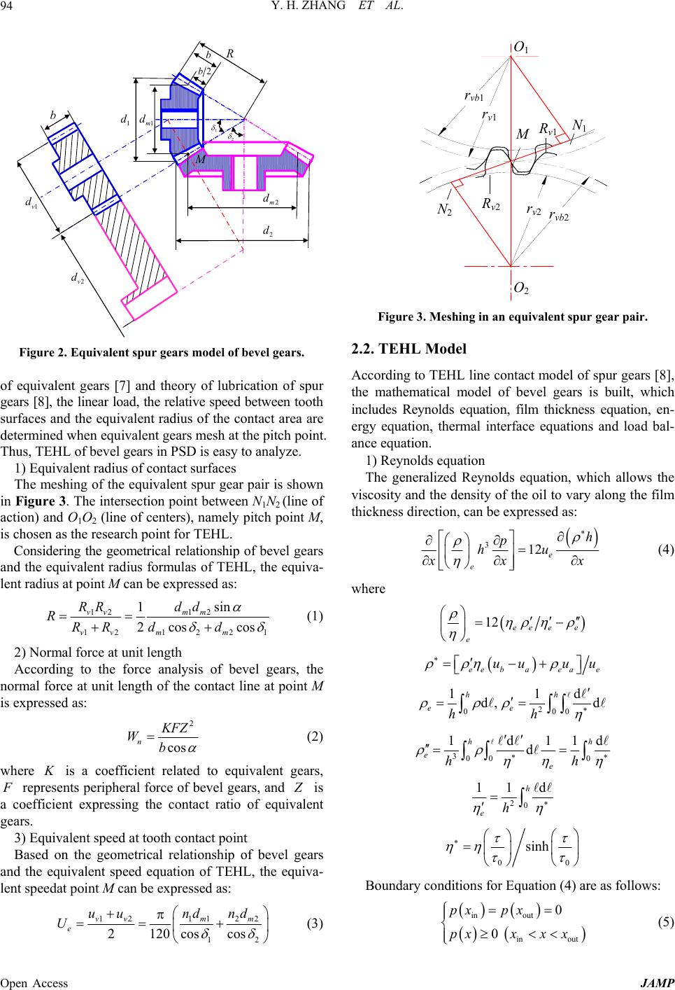 Y. H. ZHANG ET AL. 94 b 2v d 1v d 1m d 1 d 2m d 2 d b R 1 2 2b M Figure 2. Equivalent spur gears model of bevel gears. of equivalent gears [7] and theory of lubrication of spur gears [8], the linear load, the relative speed between tooth surfaces and the equivalent radius of the contact area are determined when equivalent gears mesh at the pitch point. Thus, TEHL of bevel gears in PSD is easy to analyze. 1) Equivalent radius of contact surfaces The meshing of the equivalent spur gear pair is shown in Figure 3. The intersection point between N1N2 (line of action) and O1O2 (line of centers), namely pitch point M, is chosen as the research point for TEHL. Considering the geometrical relationship of bevel gears and the equivalent radius formulas of TEHL, the equiva- lent radius at point M can be expressed as: 121 2 1212 2 sin 1 2cos cos vv mm vv mm RRd d RRR dd 1 (1) 2) Normal force at unit length According to the force analysis of bevel gears, the normal force at unit length of the contact line at point M is expressed as: 2 cos n K FZ Wb (2) where K is a coefficient related to equivalent gears, F represents peripheral force of bevel gears, and Z is a coefficient expressing the contact ratio of equivalent gears. 3) Equivalent speed at tooth contact point Based on the geometrical relationship of bevel gears and the equivalent speed equation of TEHL, the equiva- lent speedat point M can be expressed as: 12 1122 12 2120 coscos vvm m e uund nd U (3) O 2 O 1 r vb1 r vb2 r v2 r v1 N 1 N 2 R v1 R v2 M Figure 3. Meshing in an equivalent spur gear pair. 2.2. TEHL Model According to TEHL line contact model of spur gears [8], the mathematical model of bevel gears is built, which includes Reynolds equation, film thickness equation, en- ergy equation, thermal interface equations and load bal- ance equation. 1) Reynolds equation The generalized Reynolds equation, which allows the viscosity and the density of the oil to vary along the film thickness direction, can be expressed as: 312 e e h p hu x xx (4) where 12 ee ee e ee baeae uu uu 2 000 11 d, d hh ee hh d 300 0 1d11 d hh eeh h d 20 11 d h eh 00 sinh Boundary conditions for Equation (4) are as follows: in out in out 0 0 px px pxxx x (5) Open Access JAMP 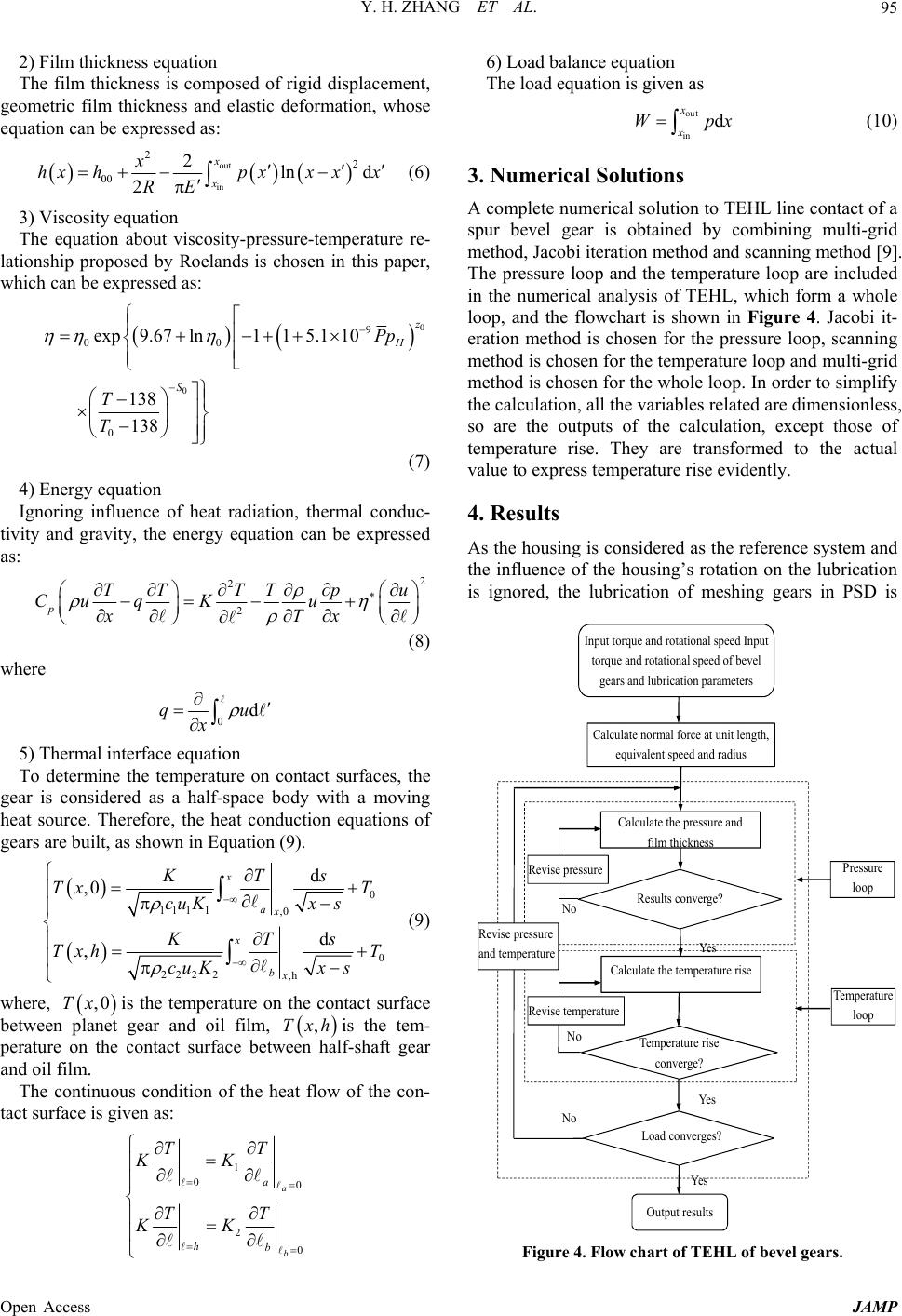 Y. H. ZHANG ET AL. 95 2) Film thickness equation The film thickness is composed of rigid displacement, geometric film thickness and elastic deformation, whose equation can be expressed as: out in 22 00 2ln d 2 x x x hxhpxx xx RE (6) 3) Viscosity equation The equation about viscosity-pressure-temperature re- lationship proposed by Roelands is chosen in this paper, which can be expressed as: 0 0 9 00 0 exp9.67ln115.1 10 138 138 z H S Pp T T (7) 4) Energy equation Ignoring influence of heat radiation, thermal conduc- tivity and gravity, the energy equation can be expressed as: 2 2 2 pTTTT pu Cu qKu xTx (8) where 0dqu x 5) Thermal interface equation To determine the temperature on contact surfaces, the gear is considered as a half-space body with a moving heat source. Therefore, the heat conduction equations of gears are built, as shown in Equation (9). 0 111 1,0 0 222 2,h d ,0 d , x ax x bx KTs Tx T cuKx s KTs Txh T cuKx s (9) where, is the temperature on the contact surface between planet gear and oil film, is the tem- perature on the contact surface between half-shaft gear and oil film. ,0Tx ,Txh The continuous condition of the heat flow of the con- tact surface is given as: 1 00 2 0 a b a hb TT KK TT KK 6) Load balance equation The load equation is given as out in d x x Wpx (10) 3. Numerical Solutions A complete numerical solution to TEHL line contact of a spur bevel gear is obtained by combining multi-grid method, Jacobi iteration method and scanning method [9]. The pressure loop and the temperature loop are included in the numerical analysis of TEHL, which form a whole loop, and the flowchart is shown in Figure 4. Jacobi it- eration method is chosen for the pressure loop, scanning method is chosen for the temperature loop and multi-grid method is chosen for the whole loop. In order to simplify the calculation, all the variables related are dimensionless, so are the outputs of the calculation, except those of temperature rise. They are transformed to the actual value to express temperature rise evidently. 4. Results As the housing is considered as the reference system and the influence of the housing’s rotation on the lubrication is ignored, the lubrication of meshing gears in PSD is Calculate normal force at unit length, equivalent speed and radius Calculate the pressure and film thickness Results converge? Calculate the temperature rise Temperature rise converge? Load converges? Pressure loop Temperature loop No Yes Yes No No Yes Output results Revise pressure Revise temperature Revise pressure and temperature Input torque and rotational speed Input torque and rotational speed of bevel gears and lubrication parameters Figure 4. Flow chart of TEHL of bevel gears. Open Access JAMP 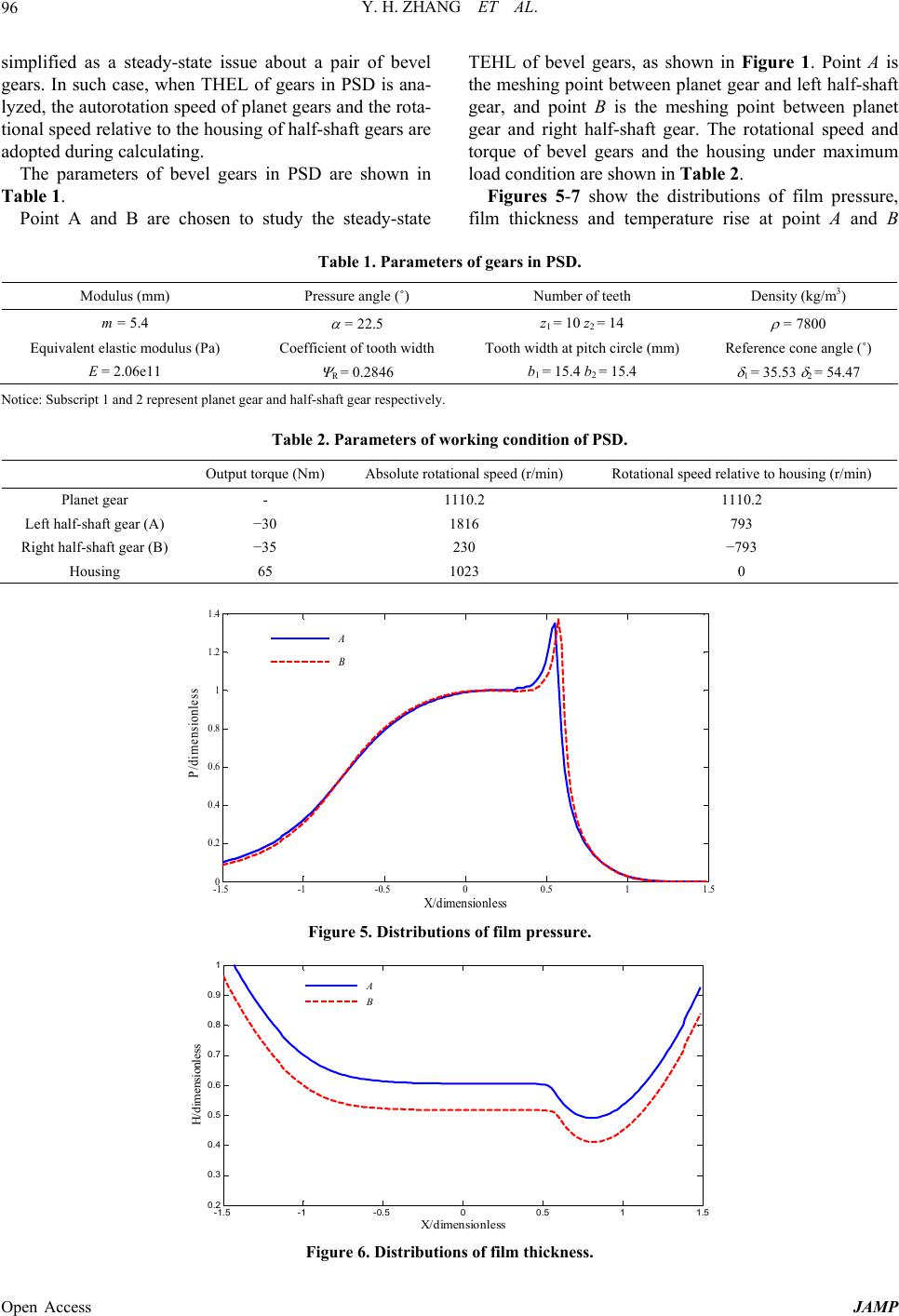 Y. H. ZHANG ET AL. Open Access JAMP 96 TEHL of bevel gears, as shown in Figure 1. Point A is the meshing point between planet gear and left half-shaft gear, and point B is the meshing point between planet gear and right half-shaft gear. The rotational speed and torque of bevel gears and the housing under maximum load condition are shown in Table 2. simplified as a steady-state issue about a pair of bevel gears. In such case, when THEL of gears in PSD is ana- lyzed, the autorotation speed of planet gears and the rota- tional speed relative to the housing of half-shaft gears are adopted during calculating. The parameters of bevel gears in PSD are shown in Table 1. Figures 5-7 show the distributions of film pressure, film thickness and temperature rise at point A and B Point A and B are chosen to study the steady-state Table 1. Parameters of gears in PSD. Modulus (mm) Pressure angle (˚) Number of teeth Density (kg/m3) m = 5.4 = 22.5 z1 = 10 z2 = 14 = 7800 Equivalent elastic modulus (Pa) Coefficient of tooth width Tooth width at pitch circle (mm) Reference cone angle (˚) E = 2.06e11 R = 0.2846 b1 = 15.4 b2 = 15.4 1 = 35.53 2 = 54.47 Notice: Subscript 1 and 2 represent planet gear and half-shaft gear respectively. Table 2. Parameters of working condition of PSD. Output torque (Nm) Absolute rotational speed (r/min) Rotational speed relative to housing (r/min) Planet gear - 1110.2 1110.2 Left half-shaft gear (A) −30 1816 793 Right half-shaft gear (B) −35 230 −793 Housing 65 1023 0 -1.5 -1 -0.500.5 11.5 0 0.2 0.4 0.6 0.8 1 1.2 1.4 X/dimensionless P/dimensionless A B Figure 5. Distributions of film pressure. -1.5 -1 -0.5 00.5 11.5 0.2 0.3 0.4 0.5 0.6 0.7 0.8 0.9 1 X/dimensionless H/dimensi onless A B Figure 6. Distributions of film thickness. 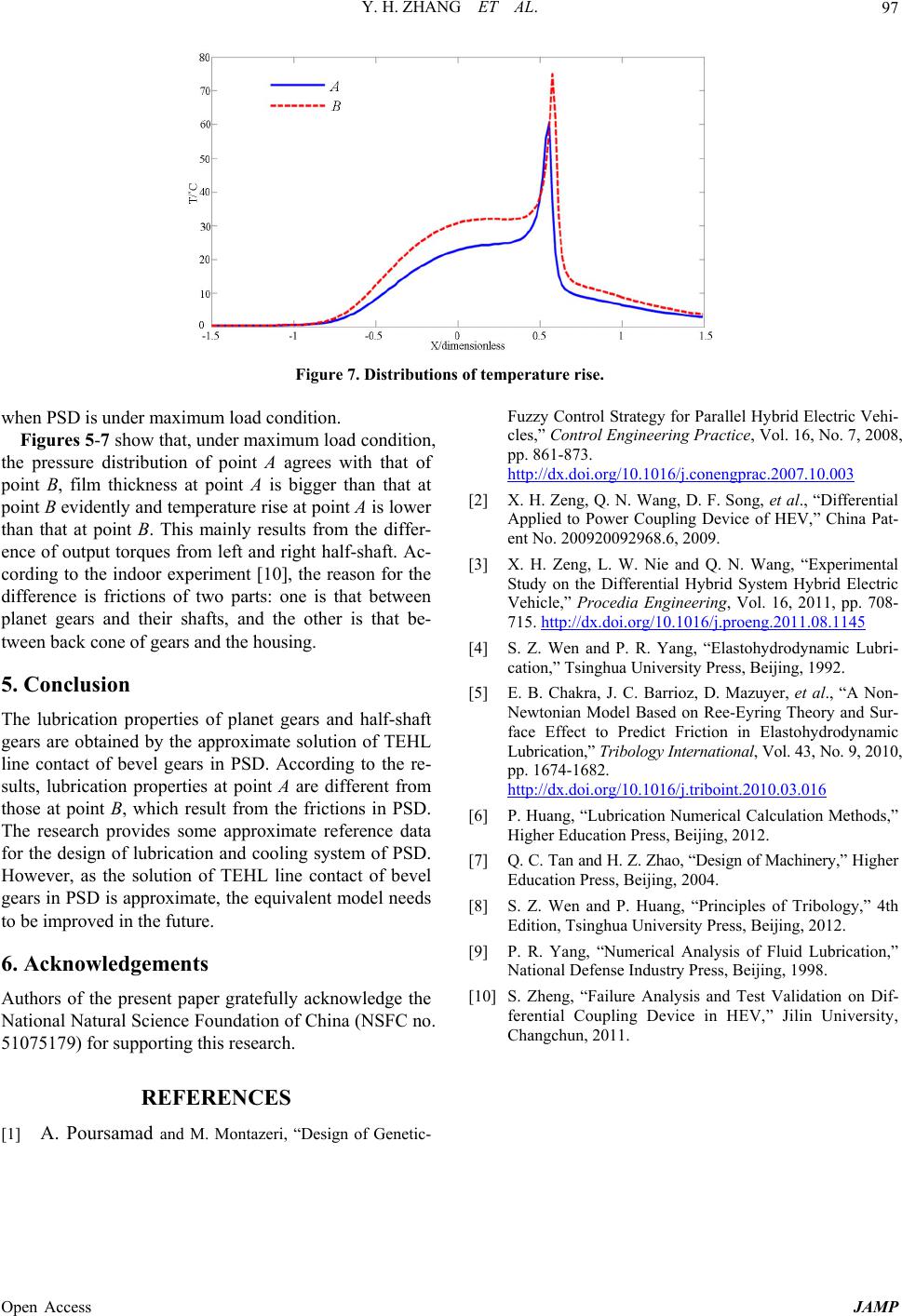 Y. H. ZHANG ET AL. 97 Figure 7. Distributions of temperature rise. when PSD is under maximum load condition. Figures 5-7 show that, under maximum load condition, the pressure distribution of point A agrees with that of point B, film thickness at point A is bigger than that at point B evidently and temperature rise at point A is lower than that at point B. This mainly results from the differ- ence of output torques from left and right half-shaft. Ac- cording to the indoor experiment [10], the reason for the difference is frictions of two parts: one is that between planet gears and their shafts, and the other is that be- tween back cone of gears and the housing. 5. Conclusion The lubrication properties of planet gears and half-shaft gears are obtained by the approximate solution of TEHL line contact of bevel gears in PSD. According to the re- sults, lubrication properties at point A are different from those at point B, which result from the frictions in PSD. The research provides some approximate reference data for the design of lubrication and cooling system of PSD. However, as the solution of TEHL line contact of bevel gears in PSD is approximate, the equivalent model needs to be improved in the future. 6. Acknowledgements Authors of the present paper gratefully acknowledge the National Natural Science Foundation of China (NSFC no. 51075179) for supporting this research. REFERENCES [1] A. Poursamad and M. Montazeri, “Design of Genetic- Fuzzy Control Strategy for Parallel Hybrid Electric Vehi- cles,” Control Engineering Practice, Vol. 16, No. 7, 2008, pp. 861-873. http://dx.doi.org/10.1016/j.conengprac.2007.10.003 [2] X. H. Zeng, Q. N. Wang, D. F. Song, et al., “Differential Applied to Power Coupling Device of HEV,” China Pat- ent No. 200920092968.6, 2009. [3] X. H. Zeng, L. W. Nie and Q. N. Wang, “Experimental Study on the Differential Hybrid System Hybrid Electric Vehicle,” Procedia Engineering, Vol. 16, 2011, pp. 708- 715. http://dx.doi.org/10.1016/j.proeng.2011.08.1145 [4] S. Z. Wen and P. R. Yang, “Elastohydrodynamic Lubri- cation,” Tsinghua University Press, Beijing, 1992. [5] E. B. Chakra, J. C. Barrioz, D. Mazuyer, et al., “A Non- Newtonian Model Based on Ree-Eyring Theory and Sur- face Effect to Predict Friction in Elastohydrodynamic Lubrication,” Tri bology I nternational, Vol. 43, No. 9, 2010, pp. 1674-1682. http://dx.doi.org/10.1016/j.triboint.2010.03.016 [6] P. Huang, “Lubrication Numerical Calculation Methods,” Higher Education Press, Beijing, 2012. [7] Q. C. Tan and H. Z. Zhao, “Design of Machinery,” Higher Education Press, Beijing, 2004. [8] S. Z. Wen and P. Huang, “Principles of Tribology,” 4th Edition, Tsinghua University Press, Beijing, 2012. [9] P. R. Yang, “Numerical Analysis of Fluid Lubrication,” National Defense Industry Press, Beijing, 1998. [10] S. Zheng, “Failure Analysis and Test Validation on Dif- ferential Coupling Device in HEV,” Jilin University, Changchun, 2011. Open Access JAMP |