

Paper Menu >>
Journal Menu >>
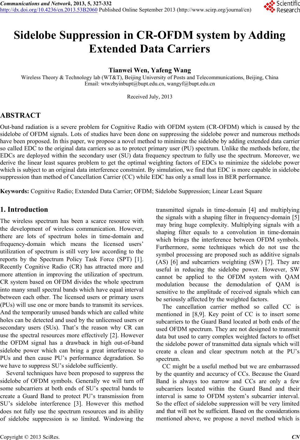 Communications and Network, 2013, 5, 327-332 http://dx.doi.org/10.4236/cn.2013.53B2060 Published Online September 2013 (http://www.scirp.org/journal/cn) Sidelobe Suppression in CR-OFDM system by Adding Extended Data Carriers Tianwei Wen, Yafeng Wang Wireless Theory & Technology lab (WT&T), Beijing University of Posts and Telecommunications, Beijing, China Email: [email protected].cn, [email protected] Received July, 2013 ABSTRACT Out-band radiation is a severe problem for Cognitive Radio with OFDM system (CR-OFDM) which is caused by the sidelobe of OFDM signals. Lots of studies have been done on suppressing the sidelobe power and numerous methods have been proposed. In this paper, we propose a novel method to minimize the sidelobe by adding extended data carrier so called EDC to the original data carriers so as to protect primary user (PU) spectrum. Unlik e the methods before, the EDCs are deployed within the secondary user (SU) data frequency spectrum to fully use the spectrum. Moreover, we derive the linear least squares problem to get the optimal weighting factors of EDCs to minimize the sidelobe power which is subject to an original data in terference constraint. By simulation, we find that EDC is more capable in sidelobe suppression than method of Cancellation Carrier (CC) while EDC has only a small loss in BER performance. Keywords: Cognitive Radio; Extended Data Carrier; OFDM; Sidelobe Suppression; Linear Least Square 1. Introduction The wireless spectrum has been a scarce resource with the development of wireless communication. However, there are lots of spectrum holes in time-domain and frequency-domain which means the licensed users’ utilization of spectrum is still very low according to the reports by the Spectrum Policy Task Force (SPT) [1]. Recently Cognitive Radio (CR) has attracted more and more attention in improving the utilization of spectrum. CR system based on OFDM divides the whole spectrum into many small spectral bands which have equal interval between each other. The licensed users or primary users (PUs) will use one or more bands to transmit its services. And the temporarily unused bands which are called white holes can be detected and used by the unlicensed users or secondary users (SUs). That’s the reason why CR can use the spectral resources more effectively [2]. However the OFDM signal has a drawback in high out-of-band sidelobe power which can bring a great interference to PUs and then cause PU’s performance degradation. So we have to suppress SU’s sidelobe sufficiently. Several techniques have been proposed to suppress the sidelobe of OFDM symbols. Generally we will turn off some subcarriers at both ends of SU’s spectral bands to create a Guard Band to protect PU’s transmission from SU’s sidelobe interference [3]. However this method does not fully use the spectrum resources and its ability of sidelobe suppression is so limited. Windowing the transmitted signals in time-domain [4] and multiplying the signals with a shaping filter in frequency-domain [5] may bring huge complexity. Multiplying signals with a shaping filter equals to a convolution in time-domain which brings the interference between OFDM symbols. Furthermore, some techniques which do not use the symbol processing are proposed such as additive signals (AS) [6] and subcarriers weighting (SW) [7]. They are useful in reducing the sidelobe power. However, SW cannot be applied to the OFDM system with QAM modulation because the demodulation of QAM is sensitive to the amplitude of received signals which can be seriously affected by the weighted factors. The cancellation carrier method so called CC is mentioned in [8,9]. Key point of CC is to insert some subcarriers to the Guard Band located at both ends of the used OFDM spectrum. They are not designed to transmit data but used to carry complex weighted factors to offset the sidelobe power of transmitted data signals which will create a clean and clear spectrum notch at the PU’s spectrum. CC might be a useful method but we are embarrassed by the quantity and accuracy of CCs. Because the Guard Band is always too narrow and CCs are only a few subcarriers located within the Guard Band and their interval is same to OFDM system’s subcarrier interval. So the effect of sidelobe suppression will be very limited and that will not be sufficient. Based on the considerations mentioned above, we propose a novel method which is C opyright © 2013 SciRes. CN 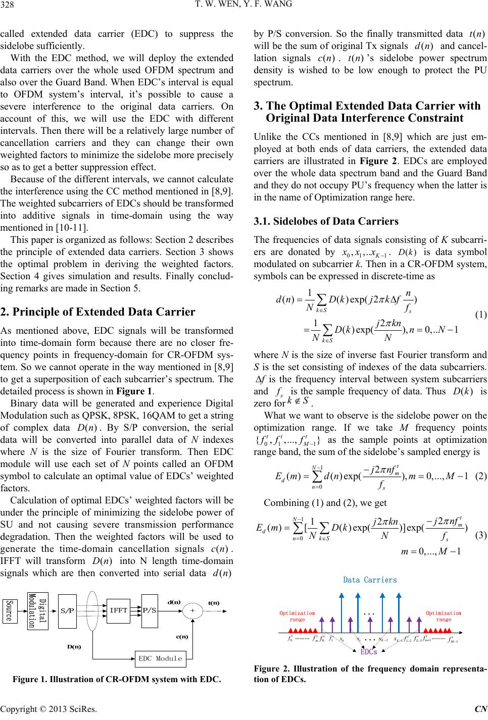 T. W. WEN, Y. F. WANG 328 called extended data carrier (EDC) to suppress the sidelobe sufficiently. With the EDC method, we will deploy the extended data carriers over the whole used OFDM spectrum and also over the Guard Band. When EDC’s interval is equal to OFDM system’s interval, it’s possible to cause a severe interference to the original data carriers. On account of this, we will use the EDC with different intervals. Then there will be a relatively large number of cancellation carriers and they can change their own weighted factors to minimize the sidelobe more precisely so as to get a better suppression effect. Because of the different intervals, we cannot calculate the interference using the CC method mentioned in [8,9]. The weighted subcarriers of EDCs should be transformed into additive signals in time-domain using the way mentioned in [10-11]. This paper is organized as follows: Section 2 describes the principle of extended data carriers. Section 3 shows the optimal problem in deriving the weighted factors. Section 4 gives simulation and results. Finally conclud- ing remarks are made in Section 5. 2. Principle of Extended Data Carrier As mentioned above, EDC signals will be transformed into time-domain form because there are no closer fre- quency points in frequency-domain for CR-OFDM sys- tem. So we cannot operate in the way mentioned in [8,9] to get a superposition of each subcarrier’s spectrum. The detailed process is shown in Figure 1. Binary data will be generated and experience Digital Modulation such as QPSK, 8PSK, 16QAM to get a string of complex data . By S/P conversion, the serial data will be converted into parallel data of N indexes where N is the size of Fourier transform. Then EDC module will use each set of N points called an OFDM symbol to calculate an optimal value of EDCs’ weighted factors. ()Dn Calculation of optimal EDCs’ weigh ted factors will be under the principle of minimizing the sidelobe power of SU and not causing severe transmission performance degradation. Then the weighted factors will be used to generate the time-domain cancellation signals . IFFT will transform into N length time-domain signals which are then converted into serial data ()cn ()dn ()Dn Figure 1. Illustration of CR-OFDM system with EDC. by P/S conversion. So the finally transmitted data will be the sum of original Tx signals and cancel- lation signals . ’s sidelobe power spectrum density is wished to be low enough to protect the PU spectrum. ()tn ()dn ()cn ()tn 3. The Optimal Extended Data Carrier with Original Data Interference Constraint Unlike the CCs mentioned in [8,9] which are just em- ployed at both ends of data carriers, the extended data carriers are illustrated in Figure 2. EDCs are employed over the whole data spectrum band and the Guard Band and they do not occupy PU’s frequency when the latter is in the name of Optimization range here. 3.1. Sidelobes of Data Carriers The frequencies of data signals consisting of K subcarri- ers are donated by 01 1 ,,.. K x xx . is data symbol modulated on subcarrier k. Then in a CR-OFDM system, symbols can be expressed in discrete-time as ()Dk 1 ( )( )exp( 2) 12 ()exp(),0,.. 1 kS s kS n dnDkjk f Nf jkn Dkn N NN (1) where N is the size of inverse fast Fourier transform and S is the set consisting of indexes of the data subcarriers. f is the frequency interval between system subcarriers and s f is the sample frequency of data. Thus is zero forkS ()Dk . What we want to observe is the sidelobe power on the optimization range. If we take M frequency points 01 1 as the sample points at optimization range band, the sum of the sidelobe’s sampled energy is { ,,...,} tt t M ff f 1 0 2 ()( )exp(),0,...,1 t Nm dns jnf Em dnmM f (2) Combini ng (1 ) and (2), we ge t 1 0 2 12 ()[( )exp()]exp() 0,..., 1 t Nm dnkS s jnf jkn Em Dk NN mM f (3) 0t f t m f 1 t m f 1 t M f 0c f 1c f -2 c L f 1 c L f 0 x 1 x 1K x 2K x Figure 2. Illustration of the frequency domain representa- tion of EDCs. Copyright © 2013 SciRes. CN 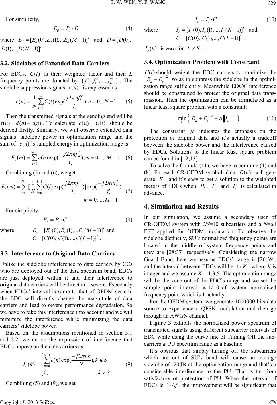 T. W. WEN, Y. F. WANG 329 For simplicity, dd EPD (4) where and [(0),(1),...( 1)] T dd dd EE EEM[(0),DD . (1),.., (1)]T DDN 3.2. Sidelobes of Extended Data Carriers For EDCs, is their weighted factor and their L frequency points are donated by 011 . The sidelobe suppression signals is expres sed as ()Cl { ,,...,} ccc L ff f )(cn 1 0 2 1 ()()exp(),0,.. 1 c Ll ls jnf cnCln N Nf (5) Then the transmit ted signals at the sending end will be . To calculate , should be derived firstly. Similarly, we will observe extended data signals’ sidelobe power in optimization range and the sum of ’s sampled energy in optimization range is ()() ()tndn cn ()cn ()cn ()Cl 1 0 2 ()()exp(),0,...,1 t Nm cns jnf Em cnmM f (6) Combini n g (5) and (6), we get 11 00 22 1 ()[( )exp()]exp() 0,..., 1 c NL l cnl ss jnf jnf Em Cl Nf mM t m f (7) For simplicity, cc EPC (8) where and [(0),(1),...( 1)] T cc cc EE EEM [(0),CC(1),..., (1)]T CCL. 3.3. Interference to Original Data Carriers Unlike the sidelobe interference to data carriers by CCs who are deployed out of the data spectrum band, EDCs are just deployed within it and their interference to original data carriers will be direct and severe. Especially, when EDCs’ interval is same to that of OFDM system, the EDC will directly change the magnitude of data carriers and lead to severe performance degradation. So we have to take this interference into account and we will minimize the interference while minimizing the data carriers’ sidelobe power. Based on the assumptions mentioned in section 3.1 and 3.2, we derive the expression of interference that EDCs impose on the data carriers as 1 0 2 ()exp(), () 0, , N n c jnk cnk S Ik N kS (9) Combini n g (5) and (9), we get ci I PC (10) where and [(0), (1),..., (1)]T cc cc II IIN [(0),CC (1),..., (1)]T CCL. () c I k is zero for kS . 3.4. Optimization Problem with Constraint ()Cl should weight the EDC carriers to minimize the 2 dc EE so as to suppress the sidelobe in the optimi- zation range sufficiently. Meanwhile EDCs’ interference should be constrained to protect the original data trans- mission. Then the optimization can be formulated as a linear least square problem with a constraint: 22 min dc c CEE I (11) The constraint indicates the emphasis on the protection of original data and it’s actually a tradeoff between the sidelobe power and the interference caused by EDCs. Solutions to the linear least square problem can be found in [12,13]. To solve the formula (11), we have to combine (4) and (8). For each CR-OFDM symbol, data will gen- erate d and it’s easy to get a solution to the weighted factors of EDCs when , and is calculated in advance. ()Dk E d Pc Pi P 4. Simulation and Results In our simulation, we assume a secondary user of CR-OFDM system with NS=10 subcarriers and a N=64 FFT applied for OFDM modulation. To observe the sidelobe distinctly, SU’s normalized frequency points are located in the middle of system frequency points and they are [28:37] respectively. Considering the narrow Guard Band, here we assume EDCs’ range is [26:39], and the interval b etween EDCs will be 1/ K where K is integer and we assume K = 1,3,5. The optimization range will be the zone out of the EDC’s range and we set the sample point interval asof system normalized frequency point which is 1 actually. 1/10 For the OFDM system, we generate 1000000 bits data source to experience a QPSK modulation and then go through an AWGN channel. Figure 3 exhibits the normalized power spectrum of transmitted signals using different subcarrier intervals of EDC while using the curve line of Turning Off the sub- carriers at PU spectrum range as a baseline. It’s obvious that simply turning off the subcarriers which are out of SU’s band will cause an average sidelobe of -20dB at the optimization range and that’s a considerable interference to the PU. That is far from satisfactory of protection of PU. When the interval of EDCs is 1 f , the improvement will be significant that C opyright © 2013 SciRes. CN 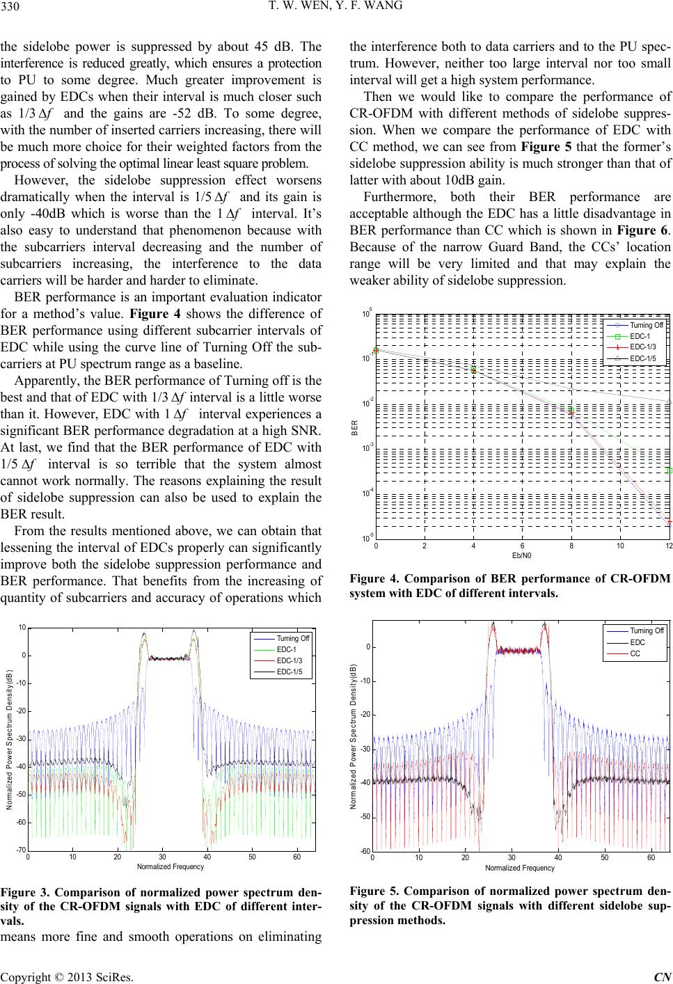 T. W. WEN, Y. F. WANG 330 the sidelobe power is suppressed by about 45 dB. The interference is reduced greatly, which ensures a protection to PU to some degree. Much greater improvement is gained by EDCs when their interval is much closer such as 1/3 f and the gains are -52 dB. To some degree, with the number of inserted carriers increasing, there will be much more choice for their weighted factors from the process of solving the optimal linear least square problem. However, the sidelobe suppression effect worsens dramatically when the interval is 1/5 f and its gain is only -40dB which is worse than the 1 f interval. It’s also easy to understand that phenomenon because with the subcarriers interval decreasing and the number of subcarriers increasing, the interference to the data carriers will be harder and harder to eliminate. BER performance is an important evaluation indicator for a method’s value. Figure 4 shows the difference of BER performance using different subcarrier intervals of EDC while using the curve line of Turning Off the sub- carriers at PU spectrum range as a baseline. Apparently, the BER performance of Turning off is the best and that of EDC with 1/3 f interval is a little worse than it. However, EDC with 1 f interval experiences a significant BER performance degradation at a high SNR. At last, we find that the BER performance of EDC with 1/5 f interval is so terrible that the system almost cannot work normally. The reasons explaining the result of sidelobe suppression can also be used to explain the BER result. From the results mentioned above, we can obtain that lessening the interval of EDCs properly can significantly improve both the sidelobe suppression performance and BER performance. That benefits from the increasing of quantity of subcarriers and accuracy of operations which 010 20 30 4050 60 -70 -60 -50 -40 -30 -20 -10 0 10 Normal i ze d Frequ enc y Norm alized P ower S pect rum Dens ity (dB) Turning Off EDC-1 EDC-1/3 EDC-1/5 Figure 3. Comparison of normalized power spectrum den- sity of the CR-OFDM signals with EDC of different inter- vals. means more fine and smooth operations on eliminating the interference both to data carriers and to the PU spec- trum. However, neither too large interval nor too small interval will get a high system performance. Then we would like to compare the performance of CR-OFDM with different methods of sidelobe suppres- sion. When we compare the performance of EDC with CC method, we can see from Figure 5 that the former’s sidelobe suppression ability is much stronger than that of latter with about 10dB gain. Furthermore, both their BER performance are acceptable although the EDC has a little disadvantage in BER performance than CC which is shown in Figure 6. Because of the narrow Guard Band, the CCs’ location range will be very limited and that may explain the weaker ability of sidelobe suppression. 0246810 1 2 10 -5 10 -4 10 -3 10 -2 10 -1 10 0 Eb/N0 BER Turning Off EDC-1 EDC-1/3 EDC-1/5 Figure 4. Comparison of BER performance of CR-OFDM system with EDC of different intervals. 010 20 30 40 50 60 -60 -50 -40 -30 -20 -10 0 Normali z ed F requency Norm alized P ower Spec trum Density(dB ) Tu r nin g Off EDC CC Figure 5. Comparison of normalized power spectrum den- sity of the CR-OFDM signals with different sidelobe sup- pression methods. C opyright © 2013 SciRes. CN 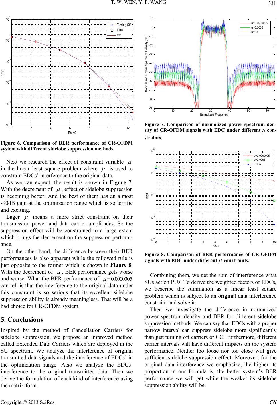 T. W. WEN, Y. F. WANG 331 0246810 12 10 -5 10 -4 10 -3 10 -2 10 -1 10 0 Eb/N0 BER Tu r n in g Off EDC CC Figure 6. Comparison of BER performance of CR-OFDM system with different sidelobe suppression methods. Next we research the effect of constraint variable in the linear least square problem where is used to constrain EDCs’ interfe rence to the original data. As we can expect, the result is shown in Figure 7. With the d ecreme nt of , effect of sidelobe suppression is becoming better. And the best of them has an almost -90dB gain at the optimization range which is so terrific and exciting. Lager means a more strict constraint on their transmission power and data carrier amplitudes. So the suppression effect will be constrained to a large extent which brings the decrement on the suppression perform- ance. On the other hand, the difference between their BER performances is also apparent while the followed rule is just opposite to the former which is shown in Figure 8. With the decremen t of , BER performance gets worse and worse. What the BER performance of 0.0000005 can tell is that the interference to the original data under this constraint is so serious that its excellent sidelobe suppression ability is already meaningless. That will be a bad choice for CR-OF DM sys tem. 5. Conclusions Inspired by the method of Cancellation Carriers for sidelobe suppression, we propose an improved method called Extended Data Carriers which are deployed in the SU spectrum. We analyze the interference of original transmitted data signals and the interference of EDCs’ in the optimization range. Also we analyze the EDCs’ interference to the original transmitted data. Then we derive the formulation of each kind of interference using the matrix form. 010 20 30 40 50 60 -90 -80 -70 -60 -50 -40 -30 -20 -10 0 10 Normal ized Frequency Normal ize d P ower Spec t rum De nsi ty (dB ) u=0 .000 0005 u=0 .000 5 u=0 .5 Figure 7. Comparison of normalized power spectrum den- sity of CR-OFDM signals with EDC under different con- straints. 012 345678910 10 -4 10 -3 10 -2 10 -1 10 0 Eb/N0 BER u=0 .00000 05 u=0 ,0005 u=0 .5 Figure 8. Comparison of BER performance of CR-OFDM signals with EDC under different constraints. Combining them, we get the sum of interference what SUs act on PUs. To derive the weighted factors of EDCs, we describe the summation as a linear least square problem which is subject to an original data interference constraint and solve it. Then we investigate the difference in normalized power spectrum density and BER for different sidelobe suppression methods. We can say that EDCs with a proper narrow interval can suppress sidelobe more significantly than just turning off carriers or CC. Furthermore, different carrier intervals will have different impa cts on t he s yste m performance. Neither too loose nor too close will give sufficient sidelobe suppression effect. Moreover, for the original data interference we emphasize, the higher its proportion in our formula is, the better system’s BER performance we will get while the weaker its sidelobe suppression ability will be. C opyright © 2013 SciRes. CN 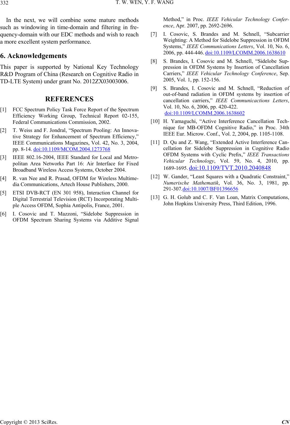 T. W. WEN, Y. F. WANG Copyright © 2013 SciRes. CN 332 In the next, we will combine some mature methods such as windowing in time-domain and filtering in fre- quency-domain with our EDC methods and wish to reach a more excellent system performance. 6. Acknowledgements This paper is supported by National Key Technology R&D Program of China (Research on Cognitive Radio in TD-LTE System) under grant No. 2012Z X 03003006. REFERENCES [1] FCC Spectrum Policy Task Force Report of the Spectrum Efficiency Working Group, Technical Report 02-155, Federal Communications Commission, 2002. [2] T. Weiss and F. Jondral, “Spectrum Pooling: An Innova- tive Strategy for Enhancement of Spectrum Efficiency,” IEEE Communications Magazines, Vol. 42, No. 3, 2004, pp. 8-14. doi:10.1109/MCOM.2004.1273768 [3] IEEE 802.16-2004, IEEE Standard for Local and Metro- politan Area Networks Part 16: Air Interface for Fixed Broadband Wireless Access Systems, October 2004. [4] R. van Nee and R. Prasad, OFDM for Wireless Multime- dia Communications, Artech House Publishers, 2000. [5] ETSI DVB-RCT (EN 301 958), Interaction Channel for Digital Terrestrial Television (RCT) Incorporating Multi- ple Access OFDM, Sophia Antipolis, France, 2001. [6] I. Cosovic and T. Mazzoni, “Sidelobe Suppression in OFDM Spectrum Sharing Systems via Additive Signal Method,” in Proc. IEEE Vehicular Technology Confer- ence, Apr. 2007, pp. 2692-2696. [7] I. Cosovic, S. Brandes and M. Schnell, “Subcarrier Weighting: A Method for Sidelobe Suppression in OFDM Systems,” IEEE Communications Letters, Vol. 10, No. 6, 2006, pp. 444-446. doi:10.1109/LCOMM.2006.1638610 [8] S. Brandes, I. Cosovic and M. Schnell, “Sidelobe Sup- pression in OFDM Systems by Insertion of Cancellation Carriers,” IEEE Vehicular Technology Conference, Sep. 2005, Vol. 1, pp. 152-156. [9] S. Brandes, I. Cosovic and M. Schnell, “Reduction of out-of-band radiation in OFDM systems by insertion of cancellation carriers,” IEEE Communicactions Letters, Vol. 10, No. 6, 2006, pp. 420-422. doi:10.1109/LCOMM.2006.1638602 [10] H. Yamaguchi, “Active Interference Cancellation Tech- nique for MB-OFDM Cognitive Radio,” in Proc. 34th IEEE Eur. Microw. Conf., Vol. 2, 2004, pp. 1105-1108. [11] D. Qu and Z. Wang, “Extended Active Interference Can- cellation for Sidelobe Suppression in Cognitive Radio OFDM Systems with Cyclic Prefix,” IEEE Transactions Vehicular Technology, Vol. 59, No. 4, 2010, pp. 1689-1695. doi:10.1109/TVT.2010.2040848 [12] W. Gander, “Lea st Squares with a Quadratic Constraint,” Numerische Mathematik, Vol. 36, No. 3, 1981, pp. 291-307.doi:10.1007/BF01396656 [13] G. H. Golub and C. F. Van Loan, Matrix Computations, John Hopkins University Press, Third Edition, 1996. |