

Paper Menu >>
Journal Menu >>
 Energy and Power Engineering, 2013, 5, 769-773 doi:10.4236/epe.2013.54B148 Published Online July 2013 (http://www.scirp.org/journal/epe) A Full Dynamic Voltage Stability Research Based on Time-domain Simulation* Yuyao Chen1, Yanping Zhang1, Jian Zhang1, Yanjun Zhang2, Lixin Song1 1China Electric Power Research Institute, Haidian District, Beijing, China 2Liaoning Electric Power Company Limited, Heping District, Shenyang, China Email: [email protected] Received April, 2013 ABSTRACT The voltage stability is substantially a dynamic stability, bu t the primary method which is more mature and engineering practical to analyze the stability of voltage is still static analysis. The time-domain simulation is an important measure in research of complex power grid. With the development of full dynamic simulation technology, the research of dy- namic voltage stability by using full dynamic simulation program which is based on time-domain simulation can be carried out. This paper uses full dynamic simulation program in dynamic voltage stability research, lays special stress on research in how generator over-excitation limiter functioned and influence in dynamic voltage stability research, and raise 2 methods and steps to figure out dynamic stable voltage in both over-excitation counted and not counted. The simulation results of examples indicate the correctness and effectiveness of these methods, and also fully verify the function and influence of generator over-excitation limiter in full dynamic voltage stability research. Keywords: Dynamic Voltage Stability; Generator Over-excitation Limiter; Time-domain Simulation 1. Introduction The voltage stab ility refers to the abili ty that all the bus es’ voltage was sustained in an acceptable range by power system when it runs in normal or disturbance circum- stances. Voltage instability stems from the unbalance between power requirements of load and supply of the system[1,2]. The voltage stability analysis falls into two major categories: static and dynamic voltage stability analysis. Static voltage stability analysis is more mature than dynamic one. But with deeper research in voltage instability, it’s gradually becomes more recognized that the voltage stability is substantially a dynamic stability and, the results of static analysis need to be verified by dynamic methods. The main dynamic voltage stability analysis methods are: small signal stability analysis, dy- namic power flow analysis, time-domain simulation, direct method analysis and bifurcation theory analy- sis[3-8]. The time-domain simulation is one of the best tools in system planning, management, running and re- search of electric power system, also in dynamic voltage stability study. Full dynamic simulation of the power system that based on time-domain simulation is such a method in which the electro-mechanical transient,mid-te rm and long-term dynamic phenomena are unified[9-11]. But voltage instability is a slow process, which means the simulation would frequently last a few minutes, sometimes even tens of minutes. It is a typical rigid nonlinear system that the time constant in simulation model vary a lot and also combine with fast and slow dynamic process. And considering of stab ility of integra- tion by parts and convergence of iteration, a long time step should not be used. Hence, a large amount of calcu- lation is needed in time-domain simulation. Furthermore, the simulation may result unreliable because of the cu- mulative error of integration by parts with an improper time step length. By analyzing the features of solving rigid nonlinear system and the key problem in existing numerical inte- gration algorithm of power system dynamic simulation, Literature [12] raise a new composite numerical integra- tion algorithm applying to full dynamic simulation which can overcome the shortages of existing algorithm that inefficient calculation and complicated intermitten t proc- essing in electro-mechanical transient process. By using full dynamic simulation program with the new algorithm in dynamic voltage stability research, this paper lays special stress on how generator over-excita- tion limiter functioned and influence in dynamic voltage stability research, and raise methods and steps to figure out dynamic stable voltage in both over-excitation *This work is supported by the Science Technology Project of State Grid Corporation of China (Contract N o . XT17201100032). Copyright © 2013 SciRes. EPE 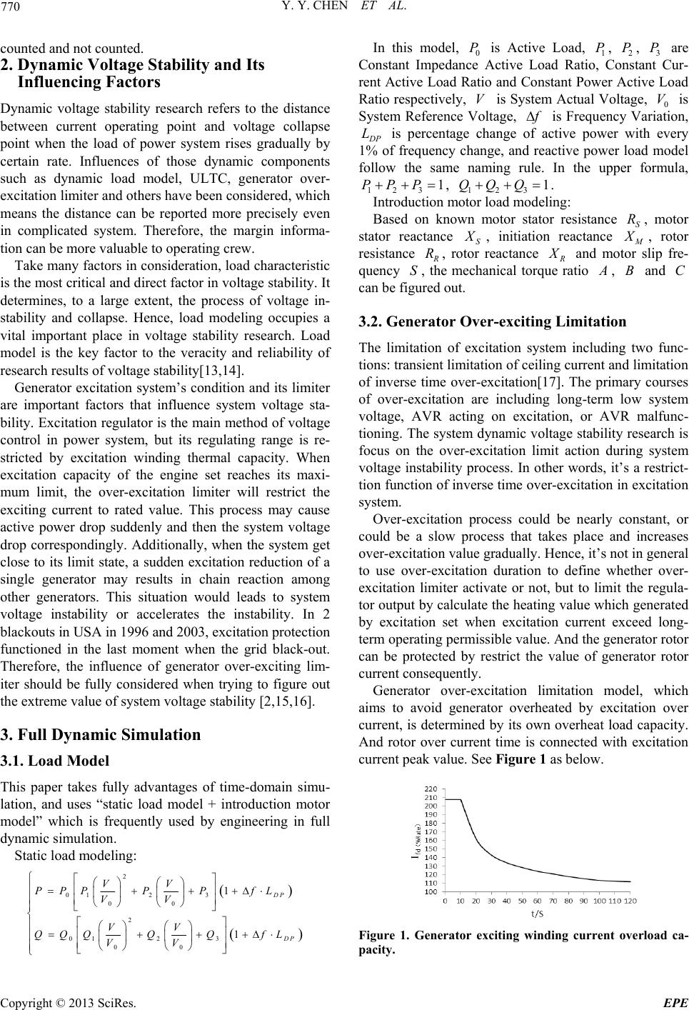 Y. Y. CHEN ET AL. 770 counted and not counted. 2. Dynamic Voltage Stability and Its Influencing Factors Dynamic voltage stability research refers to the distance between current operating point and voltage collapse point when the load of power system rises gradually by certain rate. Influences of those dynamic components such as dynamic load model, ULTC, generator over- excitation limiter and others have been considered, which means the distance can be reported more precisely even in complicated system. Therefore, the margin informa- tion can be more valuable to operating crew. Take many factors in consideration, load characteristic is the most critical and direct factor in voltage stability. It determines, to a large extent, the process of voltage in- stability and collapse. Hence, load modeling occupies a vital important place in voltage stability research. Load model is the key factor to the veracity and reliability of research results of voltage stability[13,14]. Generator excitation system’s condition and its limiter are important factors that influence system voltage sta- bility. Excitation regulator is the main method of voltage control in power system, but its regulating range is re- stricted by excitation winding thermal capacity. When excitation capacity of the engine set reaches its maxi- mum limit, the over-excitation limiter will restrict the exciting current to rated value. This process may cause active power drop suddenly and then the system voltage drop correspondingly. Additionally, when the system get close to its limit state, a sudden excitation reduction of a single generator may results in chain reaction among other generators. This situation would leads to system voltage instability or accelerates the instability. In 2 blackouts in USA in 1996 and 2003, excitation protection functioned in the last moment when the grid black-out. Therefore, the influence of generator over-exciting lim- iter should be fully considered when trying to figure out the extreme value of system voltage stability [2,15,16]. 3. Full Dynamic Simulation 3.1. Load Model This paper takes fully advantages of time-domain simu- lation, and uses “static load model + introduction motor model” which is frequently used by engineering in full dynamic simulation. Static load modeling: 2 012 3 00 2 012 3 00 1 1 DP In this model, 0 is Active Load, 1, 2, 3 are Constant Impedance Active Load Ratio, Constant Cur- rent Active Load Ratio and Constan t Power Active Load Ratio respectively, is System Actual Voltage, 0 is System Reference Voltage, P V P PP V f is Frequency Variation, D P is percentage change of active power with every 1% of frequency change, and reactive power load model follow the same naming rule. In the upper formula, L PP 123 1P , 123 1QQQ . Introduction motor load modeling: Based on known motor stator resistance , motor stator reactance S S R X , initiation reactance M X , rotor resistance R R, rotor reactance R X and motor slip fre- quency , the mechanical torque ratio S A , and can be figure d out . BC 3.2. Generator Over-exciting Limitation The limitation of excitation system including two func- tions: transien t limitatio n of ceiling curren t and limitation of inverse time over-excitation[17]. The primary courses of over-excitation are including long-term low system voltage, AVR acting on excitation, or AVR malfunc- tioning. The system dynamic voltag e stability research is focus on the over-excitation limit action during system voltage instability process. In other words, it’s a restrict- tion function of inverse time over-excitation in excitatio n system. Over-excitation process could be nearly constant, or could be a slow process that takes place and increases over-excitation value grad ually. Hence, it’s not in general to use over-excitation duration to define whether over- excitation limiter activate or not, but to limit the regula- tor output by calculate the heating value which generated by excitation set when excitation current exceed long- term operating permissible value. And the generator rotor can be protected by restrict the value of generator rotor current consequently. Generator over-excitation limitation model, which aims to avoid generator overheated by excitation over current, is determined by its own overheat load capacity. And rotor over current time is connected with excitation current peak value. See Figure 1 as below. D P VV PPPPP fL VV VV QQQQQ fL VV Figure 1. Generator exciting winding current overload ca- pacity. Copyright © 2013 SciRes. EPE 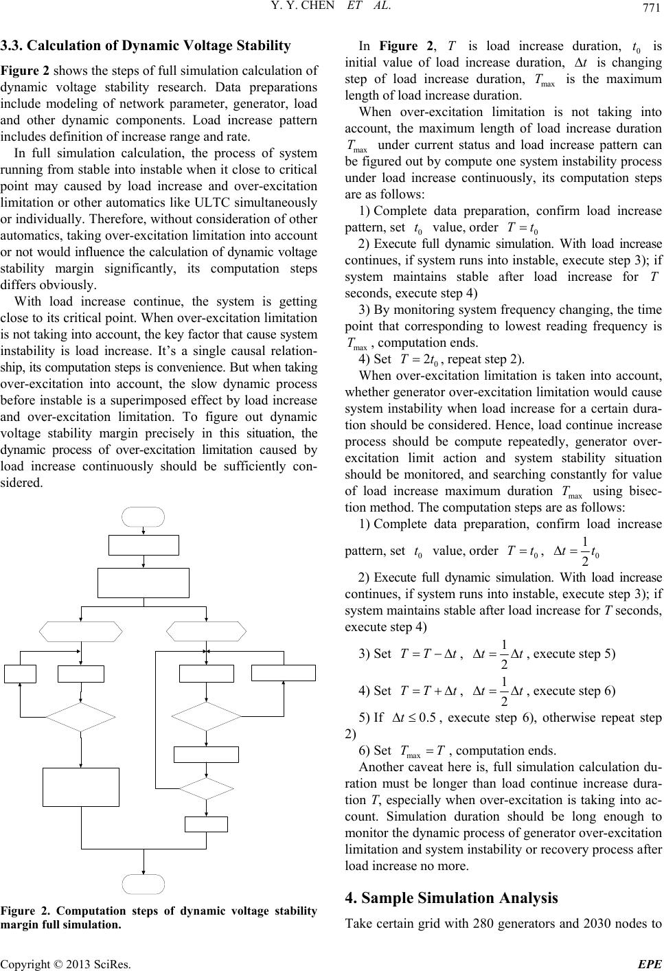 Y. Y. CHEN ET AL. 771 3.3. Calculation of Dynamic Voltage Stability Figure 2 shows the steps of full simulation calculation of dynamic voltage stability research. Data preparations include modeling of network parameter, generator, load and other dynamic components. Load increase pattern includes definition of increase range and rate. In full simulation calculation, the process of system running from stable into instable when it close to critical point may caused by load increase and over-excitation limitation or other automatics like ULTC simultaneously or individually. Therefore, without consideration of other automatics, taking over-excitatio n limitation into accoun t or not would influence the calculation of dynamic voltage stability margin significantly, its computation steps differs obviousl y . With load increase continue, the system is getting close to its critical point. When over-excitation limitation is not taking into account, the key factor that cause system instability is load increase. It’s a single causal relation- ship, its compu tation steps is conven ience. But when taking over-excitation into account, the slow dynamic process before instable is a superimposed effect by load increase and over-excitation limitation. To figure out dynamic voltage stability margin precisely in this situation, the dynamic process of over-excitation limitation caused by load increase continuously should be sufficiently con- sidered. Figure 2. Computation steps of dynamic voltage stability margin full simulation. In Figure 2, is load increase duration, 0 is initial value of load increase duration, is changing step of load increase duration, is the maximum length of load increase duration. Tt t max T When over-excitation limitation is not taking into account, the maximum length of load increase duration max under current status and load increase pattern can be figured out by compute one system instability process under load increase continuously, its computation steps are as follows: T 1) Complete data preparation, confirm load increase pattern, set t value, order Tt 0 0 2) Execute full dynamic simulation. With load increase continues, if system runs into instable, execute step 3); if system maintains stable after load increase for T seconds, execute step 4) 3) By monitoring system frequency changing, the time point that corresponding to lowest reading frequency is ma T, computation ends. x 4) Set 2Tt 0 , repeat step 2). When over-excitation limitation is taken into account, whether generator over-excitation limitation would cause system instability when load increase for a certain dura- tion should be considered. Hence, load continue increase process should be compute repeatedly, generator over- excitation limit action and system stability situation should be monitored, and searching constantly for value of load increase maximum duration max T using bisec- tion method. The computation steps are as follows: 1) Complete data preparation, confirm load increase pattern, set value, order , 0 t0 Tt0 1 2 tt 2) Execute full dynamic simulation. With load increase continues, if system runs into instable, execute step 3); if system maintains stable after load increase for T seconds, execute step 4) 3) Set TT t , 1 2 tt , execute step 5) 4) Set TT t , 1 2 tt , execute step 6) 5) If 0.5t , execute step 6), otherwise repeat step 2) 6) Set TT max , computation ends. Another caveat here is, full simulation calculation du- ration must be longer than load continue increase dura- tion T, especially when over-excitation is taking into ac- count. Simulation duration should be long enough to monitor the dynamic process of generator over-excitation limitation and system instability o r recovery process after load increase no more. 4. Sample Simulation Analysis Take certain grid with 280 generators and 2030 nodes to Copyright © 2013 SciRes. EPE 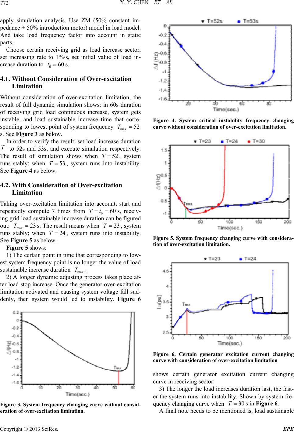 Y. Y. CHEN ET AL. 772 apply simulation analysis. Use ZM (50% constant im- pedance + 50% introduction motor) model in load model. And take load frequency factor into account in static parts. Choose certain receiving grid as load increase sector, set increasing rate to 1%/s, set initial value of load in- crease duration to s. 060t 4.1. Without Consideration of Over-excitation Limitation Without consideration of over-excitation limitation, the result of full dynamic simulation shows: in 60s duration of receiving grid load continuous increase, system gets instable, and load sustainable increase time that corre- sponding to lowest point of system frequency max 52T s. See Figure 3 as below. In order to verify the result, set load increase duration to 52s and 53s, and execute simulation respectively. The result of simulation shows when , system runs stably; when , system runs into instability. See Figure 4 as be low. T 52T 53T 4.2. With Consideration of Over-excitation Limitation Taking over-excitation limitation into account, start and repeatedly compute 7 times from 0s, receiv- ing grid load sustainable increase duration can be figured out: max s. The result means when , system runs stably; when , system runs into instability. See Figure 5 as be low. 60Tt 23T23T24T Figure 5 shows: 1) The certain point in time that corresponding to low- est system frequency point is no longer the value of lo ad sustainable increase duration T. max 2) A longer dynamic adjusting process takes place af- ter load stop increase. Once the generator over-excitation limitation activated and causing system voltage fall sud- denly, then system would led to instability. Figure 6 Figure 3. System frequency changing curve without consid- eration of over-excitation limitation. Figure 4. System critical instability frequency changing curve without consideration of over - e xcitation limitation. Figure 5. System frequency changing curve with considera- tion of over-excitation limitation. Figure 6. Certain generator excitation current changing curve with consideration of over-excitation limitation shows certain generator excitation current changing curve in receiving sector. 3) The longer the load increases duration last, the fast- er the system runs into instability. Shown by system fre- quency changing curve when 30Ts in Figure 6. A final note needs to be mentioned is, load sustainable Copyright © 2013 SciRes. EPE 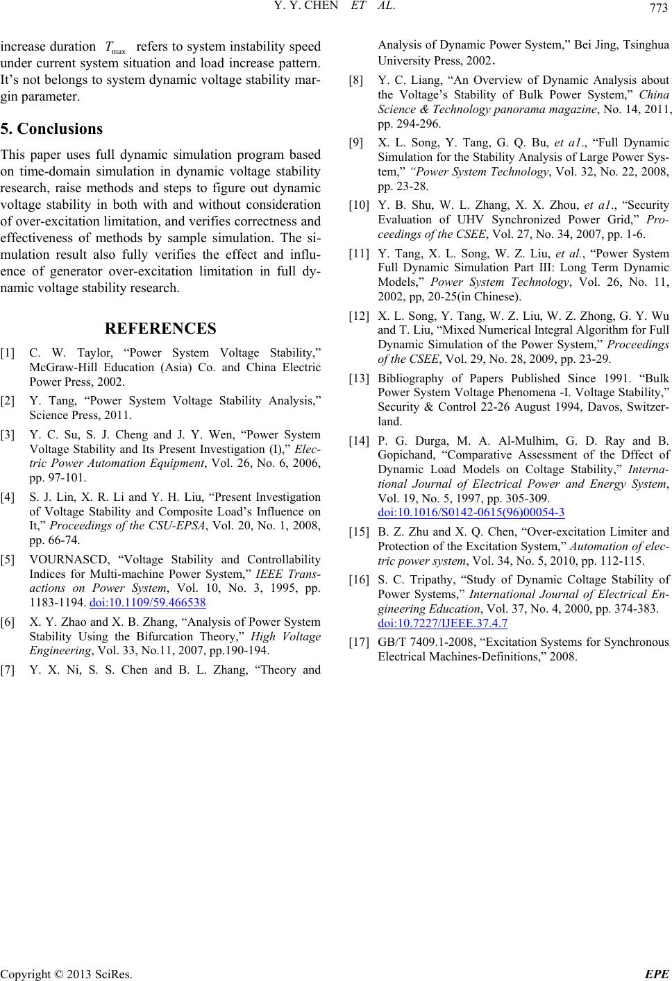 Y. Y. CHEN ET AL. Copyright © 2013 SciRes. EPE 773 increase duration max refers to system instability speed under current system situation and load increase pattern. It’s not belongs to system dynamic voltage stability mar- gin parameter. T 5. Conclusions This paper uses full dynamic simulation program based on time-domain simulation in dynamic voltage stability research, raise methods and steps to figure out dynamic voltage stability in both with and without consideration of over-excitation limitation, and verifies correctness and effectiveness of methods by sample simulation. The si- mulation result also fully verifies the effect and influ- ence of generator over-excitation limitation in full dy- namic voltage stability research. REFERENCES [1] C. W. Taylor, “Power System Voltage Stability,” McGraw-Hill Education (Asia) Co. and China Electric Power Press, 2002. [2] Y. Tang, “Power System Voltage Stability Analysis,” Science Press, 2011. [3] Y. C. Su, S. J. Cheng and J. Y. Wen, “Power System Voltage Stability and Its Present Investigation (I),” Elec- tric Power Automation Equipment, Vol. 26, No. 6, 2006, pp. 97-101. [4] S. J. Lin, X. R. Li and Y. H. Liu, “Present Investigation of Voltage Stability and Composite Load’s Influence on It,” Proceedings of the CSU-EPSA, Vol. 20, No. 1, 2008, pp. 66-74. [5] VOURNASCD, “Voltage Stability and Controllability Indices for Multi-machine Power System,” IEEE Trans- actions on Power System, Vol. 10, No. 3, 1995, pp. 1183-1194. doi:10.1109/59.466538 [6] X. Y. Zhao and X. B. Zhang, “Analy sis of Power System Stability Using the Bifurcation Theory,” High Voltage Engineering, Vol. 33, No.11, 2007, pp.190-194. [7] Y. X. Ni, S. S. Chen and B. L. Zhang, “Theory and Analysis of Dynamic Power System,” Bei Jing, Tsinghua University Press, 2002. [8] Y. C. Liang, “An Overview of Dynamic Analysis about the Voltage’s Stability of Bulk Power System,” China Science & Technology panorama magazine, No. 14, 2011, pp. 294-296. [9] X. L. Song, Y. Tang, G. Q. Bu, et a1., “Full Dynamic Simulation for the Stability Analysis of Large Power Sys- tem,” “Power System Technology, Vol. 32, No. 22, 2008, pp. 23-28. [10] Y. B. Shu, W. L. Zhang, X. X. Zhou, et a1., “Security Evaluation of UHV Synchronized Power Grid,” Pro- ceedings of the CSEE, Vol. 27, No. 34, 2007, pp. 1-6. [11] Y. Tang, X. L. Song, W. Z. Liu, et al., “Power System Full Dynamic Simulation Part III: Long Term Dynamic Models,” Power System Technology, Vol. 26, No. 11, 2002, pp, 20-25(in Chinese). [12] X. L. Song, Y. Tang, W. Z. Liu, W. Z. Zhong, G. Y. Wu and T. Liu, “Mixed Numerical Integral Algorithm for Full Dynamic Simulation of the Power System,” Proceedings of the CSEE, Vol. 29, No. 28, 2009, pp. 23-29. [13] Bibliography of Papers Published Since 1991. “Bulk Power System Voltage Phenomena -I. Voltage Stability,” Security & Control 22-26 August 1994, Davos, Switzer- land. [14] P. G. Durga, M. A. Al-Mulhim, G. D. Ray and B. Gopichand, “Comparative Assessment of the Dffect of Dynamic Load Models on Coltage Stability,” Interna- tional Journal of Electrical Power and Energy System, Vol. 19, No. 5, 1997, pp. 305-309. doi:10.1016/S0142-0615(96)00054-3 [15] B. Z. Zhu and X. Q. Chen, “Over-excitation Limiter and Protection of the Excitation System,” Automation of elec- tric power system, Vol. 34, No. 5, 2010, pp. 112-115. [16] S. C. Tripathy, “Study of Dynamic Coltage Stability of Power Systems,” International Journal of Electrical En- gineering Education, Vol. 37, No. 4, 2000, pp. 374-383. doi:10.7227/IJEEE.37.4.7 [17] GB/T 7409.1-2008, “Excitation Systems for Synchronous Electrical Machines-Definitions,” 2008. |