

Paper Menu >>
Journal Menu >>
 Energy and Power Engineering, 2013, 5, 733-739 doi:10.4236/epe.2013.54B142 Published Online July 2013 (http://www.scirp.org/journal/epe) The Control Technology Research of the Z-source Three-phase Four-bridge Arm Inverter Xiangli Li, Zhaoyang Yan , Keke Pan, Chenghao Ma, Hanhong Qi Key Lab of Power Electronics for Energy Conservation and Motor Drive of Hebei Province, Yanshan university, Qinhuangdao, China Email: [email protected] Received March, 2013 ABSTRACT Z-source inverter can boost the voltage of the DC-side, allow the two switches of the same bridge arm conducting at the same time and it has some other advantages. The zero-sequence current flows through the fourth leg of the three-phase four-leg inverter so the three-phase four-leg inverter can work with unbalanced load. This paper presents a Z-source three-phase four-leg inverter which combines a Z-source network with three-phase four-leg inverter. The circuit uses simple SPWM modulation technique and the fourth bridge arm uses fully compensated control method. The inverter can maintain a symmetrical output voltage when the proposed scheme under the unbalanced load. Keywords: Z-source Inverter; Three-phase Four-leg inverter; Unbalanced Load; Imbalanced Voltage 1. Introduction Z-source inverter[1-5] with Buck-Boost characteristic can boost the low DC power to a specified high voltage, and the two switches of the same bridge arm can conduct at the same time. Then there is no longer necessary to add the dead zone, thereby Z-source inverter can reduce the harmonic content because of the dead zone setting, and improve the quality of the power conversion. The traditional three-phase inverter can not provide pathways for the zero sequence current which is generated by un- balanced load, It is only suitable for balanced load. Three-phase four-bridge arm inverter[6-7] increases a bridge arm on the basis of the traditional three-bridge arm inverter structure. And this bridge arm constitutes midline and then eliminates the need of the midpoint transformer when the load is unbalanced, reduces the volume and weight of the system. Dq0 rotating coordi- nate variables are mutually orthogonal, there is no cou- pling, they can be individually controlled, but the disad- vantage of this method is the large amount calculation of the coordinate transformation and coordinate inverse transformation[8]. The paper separates the fourth bridge arm from the other control coupled bridge arm. The fourth bridge arm is individually controlled. Based on the advantages of the Z-source network and three-phase four-bridge arm inverter, this paper presents Z source three-phase four- bridge arm inverter, and it can improve the voltage pressure, under the unbalanced load it is able to maintain a good symmetrical output voltage. 2. Analysis of the Main Circuit 2.1. The Main Circuit The main circuit is shown in Figure 1. Z-source imped- ance network is provided by the diode D, capacitor C1, C2 and inductors L1, L2.In the design of the Z imped- ance network, the capacitance value of C1, C2 is equal and the inductance value of L1, L2 is equal. And the formula is C1 = C2 = C, L1 = L2 = L. The fourth bridge arm of the three-phase four- bridge arm inverter is added to the traditional three-phase three arms. The fourth bridge arm consists of switching tube Q7, Q8. The midpoint of the bridge arm connects the in- ductor Ln to the load neutral point. The main function of the inductance Ln is to filter the switching ripple of the neutral current. Z-source network and three-phase four- bridge arm inverter are combined to form a Z -source three-phase four-bridge arm inverter. The DC voltage Udc boost by the Z-source network then changes into alternating current through the four-leg inverter then the alternating current powers the unbalanced load through the LC filter. 2.2. Working Principle of Z-source Inverter Z-source inverter has two working conditions which are the active state and the shoot-through state. The inverter can be equivalent to a controlled current source iin. Figure 2(a) shows the active working state of the Z- source inverter’s equivalent circuit diagram. When the Copyright © 2013 SciRes. EPE 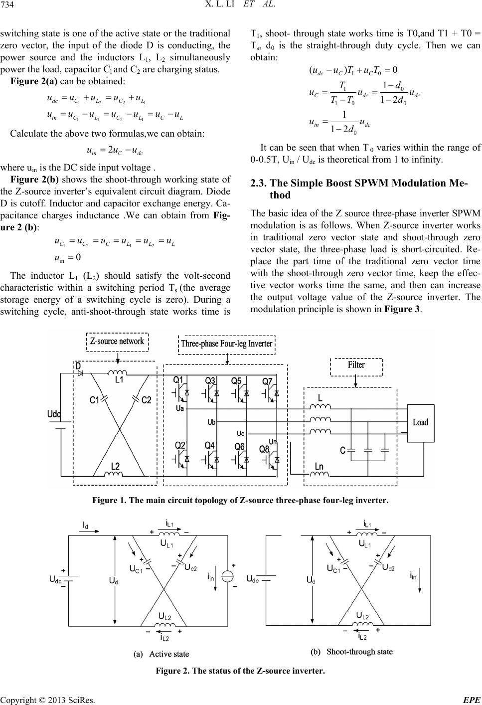 X. L. LI ET AL. 734 switching state is one of the active state or the traditional zero vector, the input of the diode D is conducting, the power source and the inductors L1, L2 simultaneously power the load, capacitor Cl and C2 are charging status. Figure 2( a) can be obtained: 12 21 11 21 dc CLCL inCL C L CL uuuuu uuuuuuu Calculate the above two formulas,we can obtain: 2 inC dc uuu where uin is the DC side input voltage . Figure 2(b) shows the shoot-through working state of the Z-source inverter’s equivalent circuit diagram. Diode D is cutoff. Inductor and capacitor exchange energy. Ca- pacitance charges inductance .We can obtain from Fig- ure 2 (b): 12 12 in 0 CCCLL uuuuuu u L The inductor L1 (L2) should satisfy the volt-second characteristic within a switching period Ts (the average storage energy of a switching cycle is zero). During a switching cycle, anti-shoot-through state works time is T1, shoot- through state works time is T0,and T1 + T0 = Ts, d0 is the straight-through duty cycle. Then we can obtain: 10 0 1 10 0 0 () 0 1 12 1 12 dc CC Cdc in dc uuTuT d T uu TT d uu d dc u It can be seen that when T 0 varies within the range of 0-0.5T, Uin / Udc is theoretical from 1 to infinity. 2.3. The Simple Boost SPWM Modulation Me- thod The basic idea of the Z source three-phase inverter SPWM modulation is as follows. When Z-source inverter works in traditional zero vector state and shoot-through zero vector state, the three-phase load is short-circuited. Re- place the part time of the traditional zero vector time with the shoot-through zero vector time, keep the effec- tive vector works time the same, and then can increase the output voltage value of the Z-source inverter. The modulation principle is shown in Figure 3. Figure 1. The main circuit topology of Z-source three-phase four-leg inverter. Figure 2. The status of the Z-source inverter. Copyright © 2013 SciRes. EPE 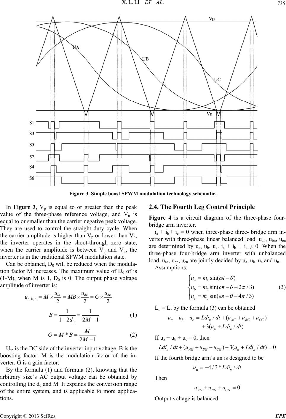 X. L. LI ET AL. 735 Figure 3. Simple boost SPWM modulation technology sche matic . In Figure 3, Vp is equal to or greater than the peak value of the three-phase reference voltage, and Vn is equal to or smaller than the carrier negative peak voltage. They are used to control the straight duty cycle. When the carrier amplitude is higher than Vp or lower than Vn, the inverter operates in the shoot-through zero state, when the carrier amplitude is between Vp and Vn, the inverter is in the traditional SPWM modulation state. Can be obtained, D0 will be reduced when the modula- tion factor M increases. The maximum value of D0 of is (1-M), when M is 1, D0 is 0. The output phase voltage amplitude of inverter is: dc dc 22 in uu uMMB G a,b,c 2 u 0 11 122 1 BdM (1) *21 M GMB M (2) Uin is the DC side of the inverter input voltage. B is the boosting factor. M is the modulation factor of the in- verter. G is a gain factor. By the formula (1) and formula (2), knowing that the arbitrary size’s AC output voltage can be obtained by controlling the d0 and M. It expands the conversion range of the entire system, and is applicable to more applica- tions. 2.4. The Fourth Leg Control Principle Figure 4 is a circuit diagram of the three-phase four- bridge arm inverter. ia + ib + ic = 0 when three-phase three- bridge arm in- verter with three-phase linear balanced load. uan, ubn, ucn are determined by ua, ub, uc. ia + ib + ic ≠ 0. When the three-phase four-bridge arm inverter with unbalanced load, uan, ubn, ucn are jointly decided by ua, ub, uc and un. Assumptions: asin( ) sin(2/ 3) sin(4/ 3) a bb cc um t um t um t (3) Ln = L, by the formula (3) can be obtained n /( 3(/) a b cnAGBGCG n uuuLdi dtuuu uLdidt ) 0 If ua + ub + uc = 0, then n /()3( /) nAGBGCGn Ldi dtuuuuLdi dt If the fourth bridge arm’s un is designed to be n4/3* / n uLdi dt Then 0 AG BG CG uuu Output voltage is balanced. Copyright © 2013 SciRes. EPE 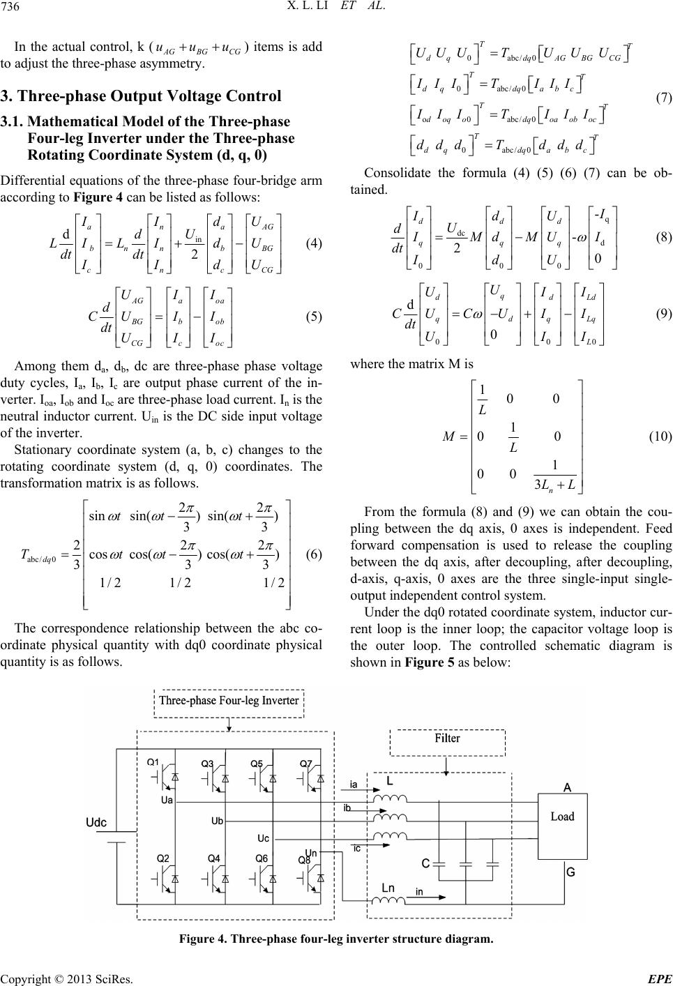 X. L. LI ET AL. 736 In the actual control, k (AG BG) items is add to adjust the three-phase asymmetry. CG uuu 3. Three-phase Output Voltage Control 3.1. Mathematical Model of the Three-phase Four-leg Inverter under the Three-phase Rotating Coordinate System (d, q, 0) Differential equations of the three-phase four-bridge arm according to Fig u r e 4 can be listed as follows: in d 2 ana bn nbBG cnc IId U d LILIdU dt dt IId AG CG U U (4) AGa oa B Gbob CGc oc UII d CUI I dt UII (5) Among them da, db, dc are three-phase phase voltage duty cycles, Ia, Ib, Ic are output phase current of the in- verter. Ioa, Iob and Ioc are three-phase load current. In is the neutral inductor current. Uin is the DC side input voltage of the inverter. Stationary coordinate system (a, b, c) changes to the rotating coordinate system (d, q, 0) coordinates. The transformation matrix is as follows. abc/ 0 22 sinsin() sin() 33 22 coscos() cos() 33 1/ 21/21/ 2 dq tt t Tttt 2 3 (6) The correspondence relationship between the abc co- ordinate physical quantity with dq0 coordinate physical quantity is as follows. 0abc/0 0abc/0 o0abc/0 0abc/0 TT d qdqAG BGCG TT dqdq abc TT doqodqoa ob oc TT dqdq abc UUUTUUU IIITIII IIIT III ddd Tddd (7) Consolidate the formula (4) (5) (6) (7) can be ob- tained. q dc d 000 - - 20 ddd qqq I IdU U d I Md MUI dt IdU (8) 00 d 0 q dd qdq L U UI CU CUII dt UI 0 Ld Lq I I (9) where the matrix M is 100 1 0 1 00 3n L ML LL 0 (10) From the formula (8) and (9) we can obtain the cou- pling between the dq axis, 0 axes is independent. Feed forward compensation is used to release the coupling between the dq axis, after decoupling, after decoupling, d-axis, q-axis, 0 axes are the three single-input single- output independent control system. Under the dq0 rotated coordinate system, inductor cur- rent loop is the inner loop; the capacitor voltage loop is the outer loop. The controlled schematic diagram is shown in Figure 5 as below: Figure 4. Three-phase four-leg inverter structure diagram. Copyright © 2013 SciRes. EPE 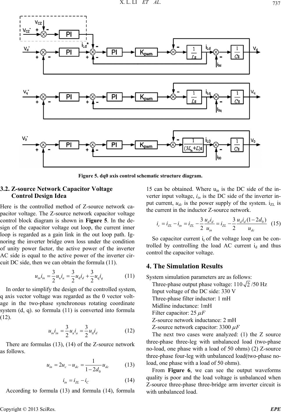 X. L. LI ET AL. 737 Figure 5. dq0 axis control schematic structure diagram. 3.2. Z-source Network Capacitor Voltage Control Design Idea Here is the controlled method of Z-source network ca- pacitor voltage. The Z-source network capacitor voltage control block diagram is shown in Figure 5. In the de- sign of the capacitor voltage out loop, the current inner loop is regarded as a gain link in the out loop path. Ig- noring the inverter bridge own loss under the condition of unity power factor, the active power of the inverter AC side is equal to the active power of the inverter cir- cuit DC side, then we can obtain the formula (11). ad 333 222 in inadq uiuiuiui q (11) In order to simplify the design of the controlled system, q axis vector voltage was regarded as the 0 vector volt- age in the two-phase synchronous rotating coordinate system (d, q). so formula (11) is converted into formula (12). a 33 22 in inad uiui ui d (12) There are formulas (13), (14) of the Z-source network as follows. 0 1 212 inc dcdc uuu u d (13) inZL C iii (14) According to formula (13) and formula (14), formula 15 can be obtained. Where uin is the DC side of the in- verter input voltage, iin is the DC side of the inverter in- put current, udc is the power supply of the system. iZL is the current in the inductor Z-source network. 0 (1 2) 33 22 dd dd cZLinZL ZL in dc uiui d iii ii uu (15) So capacitor current ic of the voltage loop can be con- trolled by controlling the load AC current id and thus control the capacitor voltage. 4. The Simulation Results System simulation parameters are as follows: Three-phase output phase voltage: 1102/50 Hz Input voltage of the DC side: 330 V Three-phase filter inductor: 1 mH Midline inductance: 1mH Filter capacitor: 25 F Z-source network inductance: 2 mH Z-source network capacitor: 3300 F The next two cases were analyzed: (1) the Z source three-phase three-leg with unbalanced load (two-phase no-load, one phase with a load of 50 ohms) (2) Z-source three-phase four-leg with unbalanced load(two-phase no- load, one phase with a load of 50 ohms). From Figure 6, we can see the output waveforms quality is poor and the load voltage is unbalanced when Z-source three-phase three-bridge arm inverter circuit is with unbalanced load. Copyright © 2013 SciRes. EPE 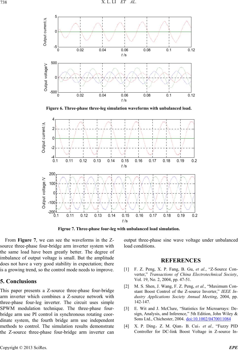 X. L. LI ET AL. 738 00.02 0.04 0.060.080.10.12 -5 0 5 t /s Out put c urrent/A 00.02 0.04 0.060.080.10.12 -500 0 500 t /s Out put voltage/V Figure 6. Three-phase three-leg simulation waveforms with unbalanced load. 0.10.11 0.12 0.13 0.14 0.150.16 0.17 0.18 0.19 0.2 -4 -2 0 2 4 t /s Output current /A 0.10.11 0.12 0.130.14 0.15 0.160.17 0.18 0.19 0.2 -200 -100 0 100 200 t/s Output v oltage /V Figrue 7. Three-phase four-le g with unbalanced load simulation. From Figure 7, we can see the waveforms in the Z- source three-phase four-bridge arm inverter system with the same load have been greatly better. The degree of imbalance of output voltage is small. But the amplitude does not have a very good stability in expectation; there is a growing trend, so the control mode needs to improve. 5. Conclusions This paper presents a Z-source three-phase four-bridge arm inverter which combines a Z-source network with three-phase four-leg inverter. The circuit uses simple SPWM modulation technique. The three-phase four- bridge arm use PI control in synchronous rotating coor- dinate system, the fourth bridge arm use independent methods to control. The simulation results demonstrate the Z-source three-phase four-bridge arm inverter can output three-phase sine wave voltage under unbalanced load conditions. REFERENCES [1] F. Z. Peng, X. P. Fang, B. Gu, et al., “Z-Source Con- verter,” Transactions of China Electrotechnical Society, Vol. 19, No. 2, 2004, pp. 47-51. [2] M. S. Shen, J. Wang, F. Z. Peng, et al., “Maximum Con- stant Boost Control of the Z-source Inverter,” IEEE In- dustry Applications Society Annual Meeting, 2004, pp. 142-147. [3] E. Wit and J. McClure, “Statistics for Microarrays: De- sign, Analysis, and Inference,” 5th Edition, John Wiley & Sons Ltd., Chichester, 2004. doi:10.1002/0470011084 [4] X. P. Ding,Z. M. Qian,B. Cui,et al., “Fuzzy PID Controller for DC-link Boost Voltage in Z-source In- Copyright © 2013 SciRes. EPE  X. L. LI ET AL. 739 verter,” Proceedings of the CSEE, Vol. 28, No. 24, 2008, pp. 31-38. [5] P. C. Loh, D. M. Vilathgamuwa, C. J. Gajanayake, Y. R. Lim and C. W. Teo, “Transient Modeling and Analysis of Pulse-Width Modulated Z-Source Inverter,” EEEE Trans- action on Power Electronics, Vol. 22, No. 2, 2009, pp. 498-507. [6] L. B. Li, Z. G. Zhao, et al., “Study on three-phase photo- voltaic grid-connected inverter system based on composi- tive control,” Power System Protection and Control, 2010, Vol. 38, No. 21, pp. 44-47. [7] L. Jun, T. C. Green and C. Feng, “Increasing Voltage Utilization inSplit-Link, Four-Wire Inverters,” IEEE Trans. on Power Electronics,” Vol. 6, No. 24, 2009, pp. 1562-1569. [8] P. C. Loh, D. M. Vilathgamuwa, C. J. Gajanayake, L. T. Wong, C. P. Ang, “Z-Source Current—Type Inverters: Digital Modulation and Logic Imple- mentation,” IEEE Transactions on Power Electron- ics, Vol. 22, No. 1, 2007, pp. 169-177. doi:10.1109/TPEL.2006.886618 Copyright © 2013 SciRes. EPE |