

Paper Menu >>
Journal Menu >>
 Communications and Network, 2013, 5, 74-79 http://dx.doi.org/10.4236/cn.2013.53B2015 Published Online September 2013 (http://www.scirp.org/journal/cn) Copyright © 2013 SciRes. CN Two-Step Resource Block Alloc at ion Algor ithm f or Data Rate Maximization in LTE Downlink Systems* Baorong Jiang1, Li Sun1,2, Pinyi Ren1 1School of Electronic and Information Engineering, Xi’an Jiaotong University, China 2National Mobile C ommunications Research Laboratory, Southeast University, China Email: [email protected], [email protected], [email protected] u.edu.cn Received June, 2013 ABSTRACT This study focu ses on resourc e bloc k allocatio n issue in t he d ownlin k tr an s miss i o n s yste m s of the Long Term Evolution (LTE). In existing LTE standa rds, all Allocation Units (AUs ) a lloca ted to any user must adopt the same Modulat io n and Coding Scheme (MCS), which is determined by the AU with the worst channel condition. Despite its simplicity, this strategy incurs significant performance degradation since the achi evable system throug hput is li mited b y the AUs hav- ing the wor st channel quality. To address this issue, a two-step resource block allocation algorithm is proposed in this paper. The algor ithm first allocates AUs to each user according to the users' priorities and the number of the ir required AUs. Then, a re-allocation mechanism is introduced. Specifically, for any given user, the AUs with the worst channel condition are removed. In this manner, the users may adopt a higher MCS level, and the achievable data rate can be increased. Finally, all the unallocated AUs are assigned among users wit hout changing the chosen MCSs, and the total thro ughput o f the s ys te m is f u rt her en ha nc ed . Si mul a ti on r e s ults s how t hat tha nk s to t he proposed algorithm, the system gains higher throughput without adding too many complexities. Keywords: Resource Block Allocatio n; Allocation Unit (AU); Two step; Re-allocation Mechanism 1. Introduction Compared with 2G and 3G networks, The LTE systems can provide higher data rates and better transmission quality. Given limited radio resources, one challenge in LTE systems is to support a large number of users and satisfy differe nt users' data rate r equi reme nts. Ortho gona l Freq uency Di vision Multiplex ing (OFDM) is used a s the basic transmission scheme in LTE downlink systems, which can achieve high system capacity. By using OFDM technique multiple users can share OFDM sub-carriers in a certain time slot [1-4]. In LT E syst em s, sub-carriers are grouped into Resource Blocks (RBs), and each RB con- sists of 12 adjacent sub-carriers. Two consecutive RBs are called an Allocation Unit (AU) [5]. In practical sys- tems, all AUs allocated to a given user should use the same MCS, which is determined by the AU with the worst channel co nd ition for this use r . Resource block allocation has been extensively studied in LTE systems. Proportional Fairness (PF) resource al- location mechanisms were presented in [5] and [6], which in reference [5] is composed of a priority adjust- ment scheme and a resource block allocation scheme. The prior ity a djustme nt scheme determines users’ priori- ties according to channel conditions and average bit rate. The resource block allocation scheme allocates resource block to the user by PF mechanism, so t he user ’s fairness is guaranteed. However, the users’ data rate requirements are not taken into consideration in this allocation sche me. Resource block allocation scheme for data rate maximi- zation is proposed in [7-9], the algorithm i n reference [7] allocates AUs to the users according to their priorities determined by users’ average channel conditions. In this manner, the minimum rate requirement of each user is satisfied. Nevertheless, for any user, the throughput is limite d by t he wo r st channe l c onditio n, a nd the AUs with better channel condition cannot be made full use of. In addition, if the users’ minimum data rate requirements are too high, the users with lower prio rities will not meet their minimum data rate requirements. It is not reasona- ble that the remaining AUs are just assigned to the user with the hi g hest prio rity. In order to solve those problems presented above, a two-step resource block allocation algorithm is proposed in this paper. The proposed algorithm consists of initial allocation The research reported in this paper was supported by the National Natural Science Foundation of China (No. 61201207), the National Science and Technology Major Project of China (No. 2012ZX03001005-004), the Open Research Fund of National Mobile Com munications Research Laboratory, Southeast University (No. 2012D04), and the Fundamental Research Funds for the Central Uni- versities of China.  B. R. JI ANG ET AL. Copyright © 2013 SciRes. CN 75 scheme and re-allocation scheme. The initial allocation scheme allocates AUs to each user based on the number of AUs required by each user and its priority. The num- ber of required AUs and the user's priority are deter- mined by proportional fairness scheme. Next, for a cer- tain user, the re -allocatio n sche me removes the AUs with the worst channel condition if the user’s data rate is in- creased by doing so. Those removed AUs are saved as free AUs to re-allocate to the other users. If there are some AUs remained after each user has reached its minimum data rate requirement, the remaining AU is assigned to the user whose M CS is not highe r than those of AU. As a result, the capacity of the proposed alloca- tion algorithm has a better performance than the Qos algorithm a nd PF al gorithm, while its co mplexity ha s not promoted so much. The rest of this paper is organized as follows. Section 2 introduces the system model and presents the op timiza- tion objective function of resource block allocation for LTE systems. In section 3, the proposed resource block allocation algorithm is described. The simulation results are shown in Section 4. Finally, Section 5 makes a con- clusion o f this p aper. 2. System Model In LTE downlink transmission systems, we assume that K active mobile users are distributed in a cell, and the total number of AUs is denoted by N. T he c onsidered system is sho wn in Figure 1. T here are five users in one cell. Vector ,1 ,1, [,, ] T kk kkN cc c=c indicates the Chan- nel Quality Indicator (CQI) of user k for N AUs. The boxes at the top of figure represent the total AUs in LTE systems. The eNB allocates AUs to each user according to the feedback of CQI. The numbers in the boxes a r e the MCS indexes of corresponding AUs. We can see the AUs allocated to the same user have different MCS in- dexes, and the MCS of the user is determined by the AU with wors t c hannel condition [10]. 1 c 2 c 3 c 4 c 5 c . . . AUs 98 7 889 U1 MCS Index : 8 9 10 U2 MCS Index : 4 11 10 U3 MCS Index : 9 U4 MCS Index : 5 9 U5 MCS Index : 7 6 7 8 94 5 56789 Figure 1 . Sys tem model of reso urce bl ock all ocati on in L TE downlink syst ems. Let ,kn c denote the CQI of user k on AU n. The minimum data tra nsmission ra te of the user k is i ndicated by k R.j r is the symbol transmission rate for a given Mod ulati on and Cod ing Sc he me (M CS) j , and J is the total number of MCS supported in the tra nsmissio n [11]. Define au N as the number of symbols for data transmis- sion in one AU. Set s T as the OFDM symbol duration time. Then, the bit rate transmitted in one AU can be calculated by: j jau au s rN rT = (1) Variable ,kn a represents the resource allocation indi- cator, with value 1 if AUn is allocated to user k and 0 otherwise. Furthermore, define the variable ,kj b as the choice of MCS of user k, and , 1 kj b= indicates that the MCS j is chosen for user k. The data rate achieved by user k can be described as: ,, 11 NJ j kk nkjau nj rabr = = =∑∑ (2) As the resource block allocation in this paper aims to achieve maximum sum data rate, the optimization prob- lem is formulated a s follows: ,, ,, ,11 1 max knkj NJ Kj k nkjau abkn j a br = == ∑∑ ∑ (3) Subject to : , kk rR k≥∀ (4) ,, 1 1,n, {0,1} K kn kn k aa = =∀∈ ∑ (5) ,, 11, , b{0,1} J kj kj j bk = =∀∈ ∑ (6) Constraint (3) is the objective function stating the achievable total rate, (4) ensures that each user can satis- fy its mini mum data rate requ irement, (5) means that one AU can only be allocated to one user, (6) presents the fact that each user must use the same MCS, which i s de- termined by the AU with the worst channel condition. It should be pointed out that finding the optimal solution would face high computational cost, so the suboptimal algorithm with low complexity is preferable 3. Proposed Algorithm The algorithm in this paper is proposed based the alloca- tion regulatio ns of LT E do wnlink t rans miss io n. As user ’s MCS is deter mined by the AU with the worst channel condition, the data rate of each user is limited, and the AUs with the better channel condition are wasted. Therefore, a t wo-step resource block allocation algorithm focus on those problems is proposed in this paper. The  B. R. JI ANG ET AL. Copyright © 2013 SciRes. CN 76 first step of proposed algorithm initially alloca te s re- source block by PF mechanis m. The next step re-allocates the AUs with the worst channel condition of each user. 3.1. Initial Allocation Scheme 1) Estimating the number of required AUs: In thi s p ap e r, we calculate the number of AUs required based on the ratio of user’s minimum data rate require- ment to channel condition [4]. Let be the average CQI of user k. is defined as the number of AUs allocated to user k. should satisfy the following conditions: (7) which means the number of AUs each user needs is pro- portional to its minimum data rate requirement, and in- versely proportional to the average channel condition. The number of AUs allocated to user k is calculated by: (8) 2) Calculati ng the prio rity of each user: Reference [12] represents two methods to calculate the priority. The one is stated in Eq. (9), which means that the users with lower minimum rate requirements have higher priorities. The next one is formulated in Eq. (10), which indicates that the user with better channel condi- tion could be first allocated. In this paper, we adopt a new way to calculate user’s priority based on the va- riance of channel conditions and minimum data rate re- quirements simultaneously. The new method is given by Eq. (11), which implies that the user with better channel condition and lower data rate requirement has higher priority. The first one: (9) The second one: (10) The third one: (11) 3) Allocating AUs to each user The initial allocation scheme is described in Table 1, which allocates AUs to the user k according to the users’ priorities and the number of AUs each user needs. Meanwhile, the minimum data rate requirement of each user is guarante ed. 3.2. Re-allocation Scheme In LTE systems, if AUs allocated to the same user have different channel qualities in terms of CQI, the MCS is determined by the lowest CQI to make sure that the data transmitted by each AU can be correctly received. Ob- viously, the users’ data rate is limited by the AUs with the worst channel condition, and the AUs with better channel condition cannot be made full use of. A solution for above problem is proposed, which is explained in Figure 2. The number of AUs allocated to each user in Figure 2 is the same as Figure 1. Assuming that each AU o nly consists of o ne symbol, the symbol transmission rate can be found in Table 2. `Before' in Figure 2 is MCS index and data rate obtained by the user without removing any AUs. `DR' in Figure 2 is abbreviatio n of data rate. Take user 2 for example, if the AU with the worst channel condition is removed, MCS index of this user turns into 5, and the data rate of this user is in- creased. The dotted boxes indicate the removed AUs, Which is saved as free AUs to allocate to other users, such as the first AU adopted to user 3 is removed by user 2, and the MCS indexes of AUs allocated to user 3 turn into higher level. Table 1. The Initial Allocation Scheme. Initial Allocation 01. Estimate the number of AUs required by according to the Eqs. (8) and (9); 02. Calculate us e rs' pr iorit ies base d on the Eqs. (10), (11) or (12), and sort them in descending order; 03. Find out the fir stAUs with better channel condition from av a il ab l e AUs for user; 04. Calculate the data rate of user by Eq. (1), if it is les s than its minimum d at a rate requirement, alloca te one more AU to this user until the minimum requirement is met.  B. R. JI ANG ET AL. Copyright © 2013 SciRes. CN 77 Figure 2 . The example to illustrate p roposed scheme. Moreover, there are several AUs remaining in practic- al applications after users have reached their minimum data rate requirements. Those remaining AUs should be assigned without changing the MCS of each user, that is to say, we allocate the remaining AUs to users, whose MCS are not hi gher t han tho se of remaining AU. By t his way, the total number of AUs allocated to some users is added, so the data rates achieved by these users are im- proved. The re-allocation scheme is stated in Table 2. 4. Simulation Results This section compares the performance of the proposed scheme, Qos algorithm [7], and PF algorithm [5] and max-rate algorithm. The simulation parameters are shown in Table 4. All simulations are obtained by aver- aging o ver 1000 channel realizations [13-14]. Table 2. MCS Table in LTE Systems. MCS Index 1 2 3 4 5 r (bit/symbo l) 0.1523 0.2344 0.3770 0.6010 0.8770 MCS Index 6 7 8 9 10 r (bit/symbo l) 1.1758 1.4766 1.9141 2.4063 2.7305 MCS Index 11 12 13 14 15 r (bit/symbo l) 3.3223 3.9023 4.5234 5.1152 5.5547 Table 3. The Re-allocation Scheme. Re-allo ca tion schem e 01. For k=1:K 02. Allocate k NAUs to us er k , and calculate k r of this user; 03. While kk rR< 04. allocate one more AU to the user; 05. End While 06. Calculate data rate ' k r without allocation of AUs with 07. the worst channel condition; 08. If ' k k rr≥ 09. Remove AUs with the worst channel condition. 10. Then 1kk= + , go to s te p 1; 11. End If 12. End For 13. Allocate the remaining AUs to users, whose MCS are not higher than those of remaining AU. Table 4. Simulation Parameters. Simulation Parameters Values System bandwidth Carrier frequency Sampling frequency Channel model Number of AUs Number of users Cha n nel feedba ck OFDM symbols per fra m e TTI duration 20MHZ 2GHZ 30.72MHZ SCM 50 6-18 Full 14 1ms QPSK:1/3,1/2,2/3,3/4,4/5 Simulation Parameters Values Modulation and coding 16QAM:1/2,2/3,3/4,4/5 64QAM:2/3,3/4,4/5 To illustrate user’s fairness achieved by each algo- rithm, the fairness factor is introduced [2], which is stated as: 2 2 11 ( )/ KK kk kk IT KT = = = ∑∑ (12) where I is the fairness factor. k T is the aver a ge data rate of user k. The closer the fairness factor obtained by algo- rithm approximates to 1, the better the fairness of the algorithm is. Figure 3 compares fairness index of the proposed scheme, Qos algorithm, PF algorithm and max-rate algo- rithm. As the max-rate algorithm aims to maximize the system throughput without considering users' require- ments, it di splays the worst in ter ms of fairness. With the increasing of the number of users, the fairness factor of max-rate algorithm is decreased sharply. The fairness factors of the other three algorithms are close. Their fairness factors are all more than 0.9 when the number of users is less than 14. The proposed algorithm exhibits the best fairness in these three algorithms, and Qos and PF algorithm are slightly lower t han it. The throughput of the system is shown in Figure 4. Because the users' requirements and remaining AUs are not considered, the throughput of PF algorithm is the lowest of all. From the point of throughput, the proposed algorithm is superior to the Qos and PF algorithm, bene- fiting from higher MCS of some users, free AUs, and the appropriate allocation of remaining AUs. Max-rate algo- rithm displays the best performance of the four algo- rithms. The curve of proposed algorithm is close to that of the max-rate algorithm. When the number of users is small, the curve of proposed algorithm is highe r t ha n t ha t of max-rate algorithm. Because of the MCS selection mechanism in LTE systems, max-rate algorithm cannot always provide the best performance. 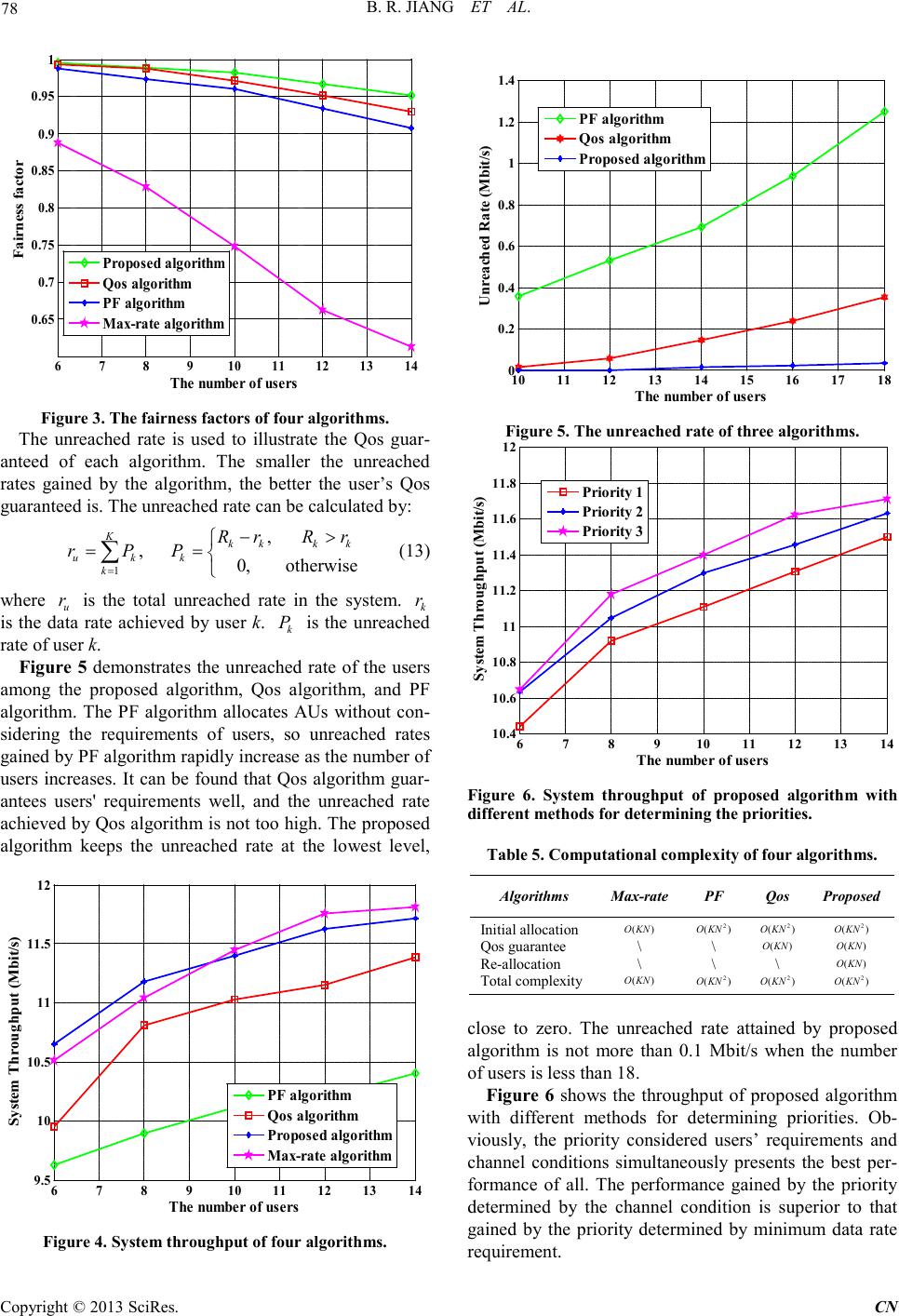 B. R. JI ANG ET AL. Copyright © 2013 SciRes. CN 78 678910 11 12 13 14 0.65 0.7 0.75 0.8 0.85 0.9 0.95 1 The numbe r of users F airn es s facto r Proposed algorithm Qos algorithm PF algorithm Max-rate algorithm Figure 3. The fairness fa ct ors of four algorithms. The unreached rate is used to illustrate the Qos guar- anteed of each algorithm. The smaller the unreached rates gained by the algorithm, the better the user’s Qos guaranteed is. The unreached rate can be calculated by: 1 , , 0, otherwise Kkkk k u kk k Rr Rr r PP = −> == ∑ (13) where u r is the total unreached rate in the system. k r is the data rate achieved by user k. k P is the unreached rate of user k. Figure 5 demonstrates the unreached rate of the users among the proposed algorithm, Qos algorithm, and PF algorithm. The PF algorithm allocates AUs without con- sidering the requirements of users, so unreached rates gained by P F algorithm rapid ly increase as the number of users increases. It can be found that Qos algorithm guar- antees users' requirements well, and the unreached rate achieved b y Qos algorithm is not too high. The proposed algorithm keeps the unreached rate at the lowest level, 678910 1112 13 14 9.5 10 10.5 11 11.5 12 The numbe r of users System Throughput (Mbit/s) PF algorithm Qos algorithm Proposed algorithm Max-rate algorithm Figure 4. System throughput of four a lgorithms. 10 11 12 13 14 15 16 1718 0 0.2 0.4 0.6 0.8 1 1.2 1.4 The number of users U nrea ched Rate (Mbit/s) PF algorithm Qos algorithm Proposed algorithm Figure 5. The unreached rate of three algorithms. 678910 11 12 13 14 10.4 10.6 10.8 11 11.2 11.4 11.6 11.8 12 The number of user s System Throughput (Mbit/s) P ri ority 1 P ri ority 2 P ri ority 3 Figure 6. System throughput of proposed algorithm with different methods for determining the priorit ies. Table 5. Compu tational complexity of four alg or ithms. Algorithms Max-ra te PF Qos Proposed Initial allocation Qos gua rantee Re-allocation Total complexity ()OKN \ \ ()OKN 2 ()O KN \ \ 2 ()O KN 2 ()O KN ()OKN \ 2 ()O KN 2 ()O KN ()OKN ()OKN 2 ()O KN close to zero. The unreached rate attained by proposed algorithm is not more than 0.1 Mbit/s when the number of users is les s t han 18 . Figure 6 shows the throughput of proposed algorithm with different methods for determining priorities. Ob- viously, the priority considered users’ requirements and channel conditions simultaneously presents the best per- formance of all. The performance gained by the priority determined by the channel condition is superior to that gained by the priority determined by minimum data rate require ment. 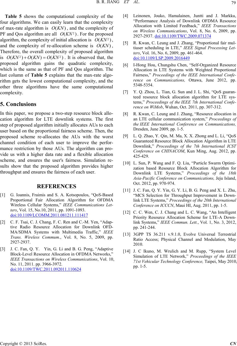 B. R. JI ANG ET AL. Copyright © 2013 SciRes. CN 79 Table 5 shows the computational complexity of the four algorithms. We can easily learn that the complexity of ma x-rate algorith m is () O KN, and the complexity of PF and Qos algo rithm a r e all 2 ()O KN . For the proposed algorithm , th e c ompl exity of initial allocation is 2 ()O KN , and the complexity of re-allocation scheme is () O KN, Therefore, the overall complexity of proposed algorithm is 22 ()()() O KNOKNO KN+= . It is observed that, the proposed algorithm gains the quadratic complexity, which is the same as that of PF and Qos algorithm. The last column of Tabl e 5 explains that the max-rate algo- rithm gets the lowest computational complexity, and the other three algorithms have the same computational complexity. 5. Conclusions In this paper, we propose a two-step resource block allo- cation algorithm for LTE downlink systems. The first step of pro posed algorithm initiall y allocates AUs to each user based on the proportional fairne ss sc he me. The n, t h e proposed scheme re-allocates the AUs with the worst channel condition of each user to improve the perfor- mance restriction by those AUs. The algorithm can pro- vide us with a higher data rate and a flexible allocation scheme, and ensures the user's fairness. Simulation re- sults show that the proposed algorithm provides higher thro ughput and ens ures the fairness of each user. REFERENCES [1] G. Ioannis, Fraimis and S. A. Kotsopoulos, “QoS-Based Proportional Fair Allocation Algorithm for OFDMA Wireless Cellular Systems,” IEEE Communications Let- ters, Vol. 15, No.10, 2011, pp. 1091-1093. doi:10.1109/LCOMM.2011.081211.111417 [2] C. F. Tsai , C. J. Chang, F. C. Ren and C.-M. Yen, “Adap- tive Radio Resource Allocation for Downlink OFD- MA/SDMA Systems with Multimedia Traffic,” IEEE Trans. Wireless Commum., Vol. 8, No. 5, 2009, pp. 2927-2937. [3] J. C. Fan, Q. Y. Yin, G. Li and B. G. Peng, “Adaptive Block-Level Resource Allocation in OFDMA Networks,” IEEE Transact ions on Wireless Communications, Vol. 10, No. 11, 2011. pp. 3966-3972. [4] Leinonen, Jouko, Hamalainen, Juntti and J. Markku, “Performance Analysis of Downlink OFDMA Resource Allocation with Limited Feedback,” IEEE Transactions on Wireless Communications, Vol. 8, No. 6, 2009, pp. 2927-2937. doi:10.1109/TWC.2011.092011.110624 doi:10.1109/TWC.2009.071374 [5] R. Kwan , C. Leung and J. Zhang, “Proportional fair mul- tiuser scheduling in LTE,” IEEE Signal Processing Let- ters, Vol. 16, No . 6, 2009, pp. 461-464. [6] I-Hong Hou, Chungshu Chen, “Self-Organized Resource Allocation in LTE Systems with Weighted Proportional Fairn es s,” Proceedings of the IEEE International Confe- rence on Communications, Ottawa, Jun e 2012, pp. 5348-5354. doi:10.1109/LSP.2009.2016449 [7] Y. Q. Zhou, L. Tian, G. Sun and J. L. Shi, “QoS guaran- teed resource block allocation algorithm for LTE sys- tems,” Proceedings of the IEEE 7th International Confe- rence on WiMob, Wuhan, Oct. 2011, pp. 307-312. [8] R. Kwa n , C . Leung and J. Zhang, “Reso urce allo catio n in an LTE cellular communication system,” Proceedings of the IEEE International Conference on Communications, Dresden , June 2009, pp. 1-5. [9] L. Q. Zhao, Y. Qin, M . M a , X . X. Zhong and L. Li, “QoS Guaranteed R esou rce B lo ck Allocatio n Algorithm in LTE Downlink,” Proceedings of the 7th International ICST Conference on CHINACOM, Kun Ming, Aug. 2012, pp. 425-429. [10] L. Sun, P. Wang and F. Q. Liu , “Particl e Swarm Optimi- zation based Resource Block Allocation Algorithm for Downlink LTE Systems,” Proceedings of the 18th Asia-Pa cific Conference o n Communications, Jeju Island, Oct. 2012, pp. 970-974. [11] J. C. Fan, Q. Y. Yin, G. Y. Li, B. G. Peng and X. L. Zhu, “MCS Selection for Throughput Improvement in Down- link LTE Systems,” Proceedings of the 20th International Conference on ICCCN, Maui HI, Aug. 2011, pp. 1-5. [12] C. C. Wen, C. J. Chang and L. C. Wang, “An Intelligent Priority Resource Allocation Scheme for LTE-A Down- link Systems,” IEEE Commun. Lett., Vol. 1, No. 3, 2012, pp. 241-244. [13] 3GPP TS 36.211 v.9.1.0, Evolve Universal Terrestrial Ratio Access; Physical Channel and Modulation, May 2010. [14] J. C Ikuno, M. Wrulich and M. Rupp, “System Level Simulation of LTE Network,” Proceedings of the IEEE 71st Vehicular Technology Conf erence, Taipei, May 2010, pp. 1-5. |