

Paper Menu >>
Journal Menu >>
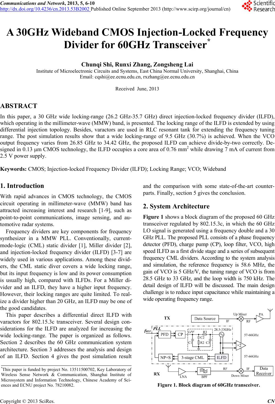 Communications and Network, 2013, 5, 6-10 http://dx.doi.org/10.4236/cn.2013.53B2002 Published Online September 2013 (http://www.scirp.org/journal/cn) A 30GHz Wideband CMOS Injection-Locked Frequency Divider for 60GHz Transceiver* Chunqi Shi, Runxi Zhang, Zongsheng Lai Institute of Microelectronic Circuits and Systems, East China Normal University, Shanghai, China Email: [email protected], [email protected] Received June, 2013 ABSTRACT In this paper, a 30 GHz wide locking-range (26.2 GHz-35.7 GHz) direct injection-locked frequency divider (ILFD), which operating in the millimeter-wave (MMW) band, is presented. The locking range of the ILFD is extended by using differential injection topology. Besides, varactors are used in RLC resonant tank for extending the frequency tuning range. The post simulation results show that a wide locking-range of 9.5 GHz (30.7%) is achieved. When the VCO output frequency varies from 26.85 GHz to 34.42 GHz, the proposed ILFD can achieve divide-by-two correctly. De- signed in 0.13 μm CMOS technology, the ILFD occupies a core area of 0.76 mm2 while drawing 7 mA of current from 2.5 V power supply. Keywords: CMOS; Injection-locked Frequency Divider (ILFD); Locking Range; VCO; Wideband 1. Introduction With rapid advances in CMOS technology, the CMOS circuit operating in millimeter-wave (MMW) band has attracted increasing interest and research [1-9], such as point-to-point communications, image sensing, and au- tomotive radar systems. Frequency dividers are key components for frequency synthesizer in a MMW PLL. Conventionally, current- mode-logic (CML) static divider [1], Miller divider [2], and injection-locked frequency divider (ILFD) [3-7] are widely used in various applications. Among these divid- ers, the CML static diver covers a wide locking range, but its input frequency is low and its power consumption is usually high, compared with ILFDs. For a Miller di- vider and an ILFD, they have a higher input frequency. However, their locking ranges are quite limited. To real- ize a divider higher than 20 GHz, an ILFD may be one of the good candidates. This paper describes a differential direct ILFD with varactors for 802.15.3c transceiver. Several design con- siderations for the ILFD are analyzed for increasing the wide locking-range. The paper is organized as follows. Section 2 describes the 60 GHz communication system architecture. Section 3 addresses the analysis and design of an ILFD. Section 4 gives the post simulation result and the comparison with some state-of-the-art counter- parts. Finally, section 5 gives the conclusion. 2. System Architecture Figure 1 shows a block diagram of the proposed 60 GHz transceiver regulated by 802.15.3c, in which the 60 GHz LO signal is generated using a frequency double and a 30 GHz PLL. The proposed PLL consists of a phase frequency detector (PFD), charge pump (CP), loop filter, VCO, high speed ILFD as a first divide stage and a series of subsequent frequency CML dividers. According to the system analysis and simulation, the reference frequency is 58.6 MHz, the gain of VCO is 5 GHz/V, the tuning range of VCO is from 28.5 GHz to 33 GHz, and the loop width is 750 kHz. The detail design of ILFD will be discussed. The main design challenge is to reduce input capacitance while maintaining a wide operating frequency range. *This paper is funded by project No. 13511500702, Key Laboratory o f Wireless Sense Network & Communication, Shanghai Institute o f Microsystem and Information Technology, Chinese Academy of Sci- ences and ECNU p ro j ect No. 78210082. Figure 1. Block diagram of 60GHz transceiver. C opyright © 2013 SciRes. CN 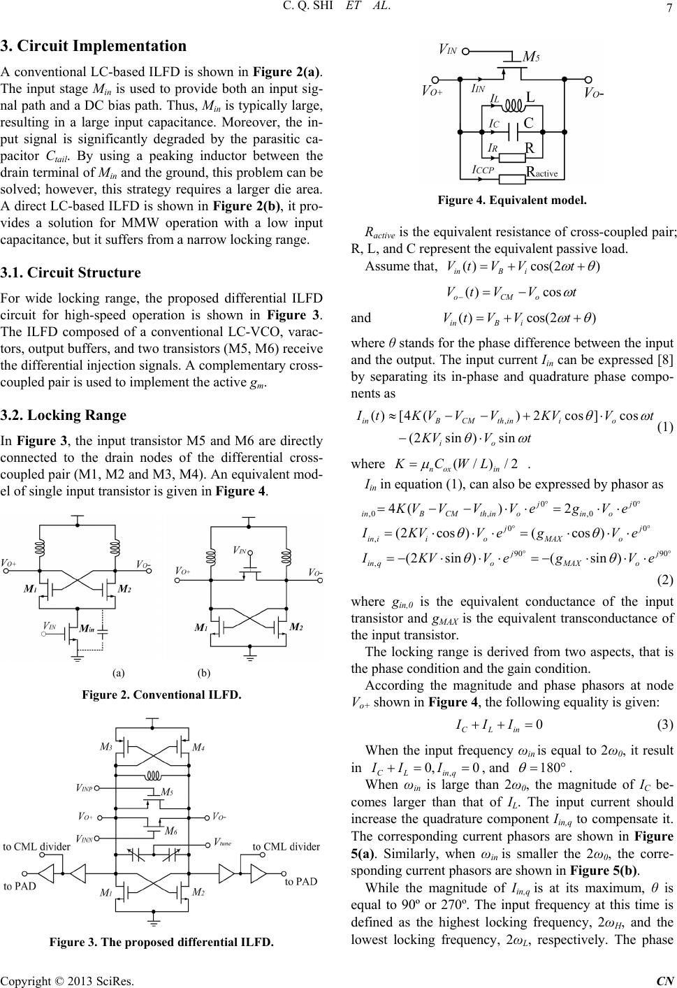 C. Q. SHI ET AL. 7 3. Circuit Implementation A conventional LC-based ILFD is shown in Figure 2(a). The input stage Min is used to provide both an input sig- nal path and a DC bias path. Thus, Min is typically large, resulting in a large input capacitance. Moreover, the in- put signal is significantly degraded by the parasitic ca- pacitor Ctail. By using a peaking inductor between the drain terminal of Min and the ground, this problem can be solved; however, this strategy requires a larger die area. A direct LC-based ILFD is shown in Figure 2(b), it pro- vides a solution for MMW operation with a low input capacitance, but it suffers from a narrow locking range. 3.1. Circuit Structure For wide locking range, the proposed differential ILFD circuit for high-speed operation is shown in Figure 3. The ILFD composed of a conventional LC-VCO, varac- tors, output buffers, and two transistors (M5, M6) receive the differential injection signals. A complementary cross- coupled pair is used to implement the active gm. 3.2. Locking Range In Figure 3, the input transistor M5 and M6 are directly connected to the drain nodes of the differential cross- coupled pair (M1, M2 and M3, M4). An equivalent mod- el of single input transistor is given in Figure 4. (a) (b) Figure 2. Conventional ILFD. Figure 3. The proposed differential ILFD. Figure 4. Equivalent model. Ractive is the equivalent resistance of cross-coupled pair; R, L, and C represent the equivalent passive load. Assume that, ()cos(2 ) inB i VtV Vt () cos oCMo Vt VVt and ()cos(2 ) inB i VtV Vt where θ stands for the phase difference between the input and the output. The input current Iin can be expressed [8] by separating its in-phase and quadrature phase compo- nents as , ( )[4()2cos]cos (2sin)sin inBCMth inio io I tKVVV KVV KVV t t (1) where (/)/2 nox in KCWL . Iin in equation (1), can also be expressed by phasor as 00 ,0, ,0 00 , 90 90 , 4() 2 (2cos )(cos ) (2sin )(sin ) jj inBCMthinoino jj in iioMAXo jj in qoMAXo KVVVVegV e IKV VegVe I KVVegV e (2) where g in,0 is the equivalent conductance of the input transistor and gMAX is the equivalent transconductance of the input transistor. The locking range is derived from two aspects, that is the phase condition and the gain condition. According the magnitude and phase phasors at node Vo+ shown in Figure 4, the following equality is given: 0 CLin III (3) When the input frequency ωin is equal to 2ω0, it result in , 0, 0 CL inq II I , and 180 . When ωin is large than 2ω0, the magnitude of IC be- comes larger than that of I L. The input current should increase the quadrature component Iin,q to compensate it. The corresponding current phasors are shown in Figure 5(a). Similarly, when ωin is smaller the 2ω0, the corre- sponding current phasors are shown in Figure 5(b). While the magnitude of Iin,q is at its maximum, θ is equal to 90º or 270º. The input frequency at this time is defined as the highest locking frequency, 2ωH, and the lowest locking frequency, 2ωL, respectively. The phase Copyright © 2013 SciRes. CN 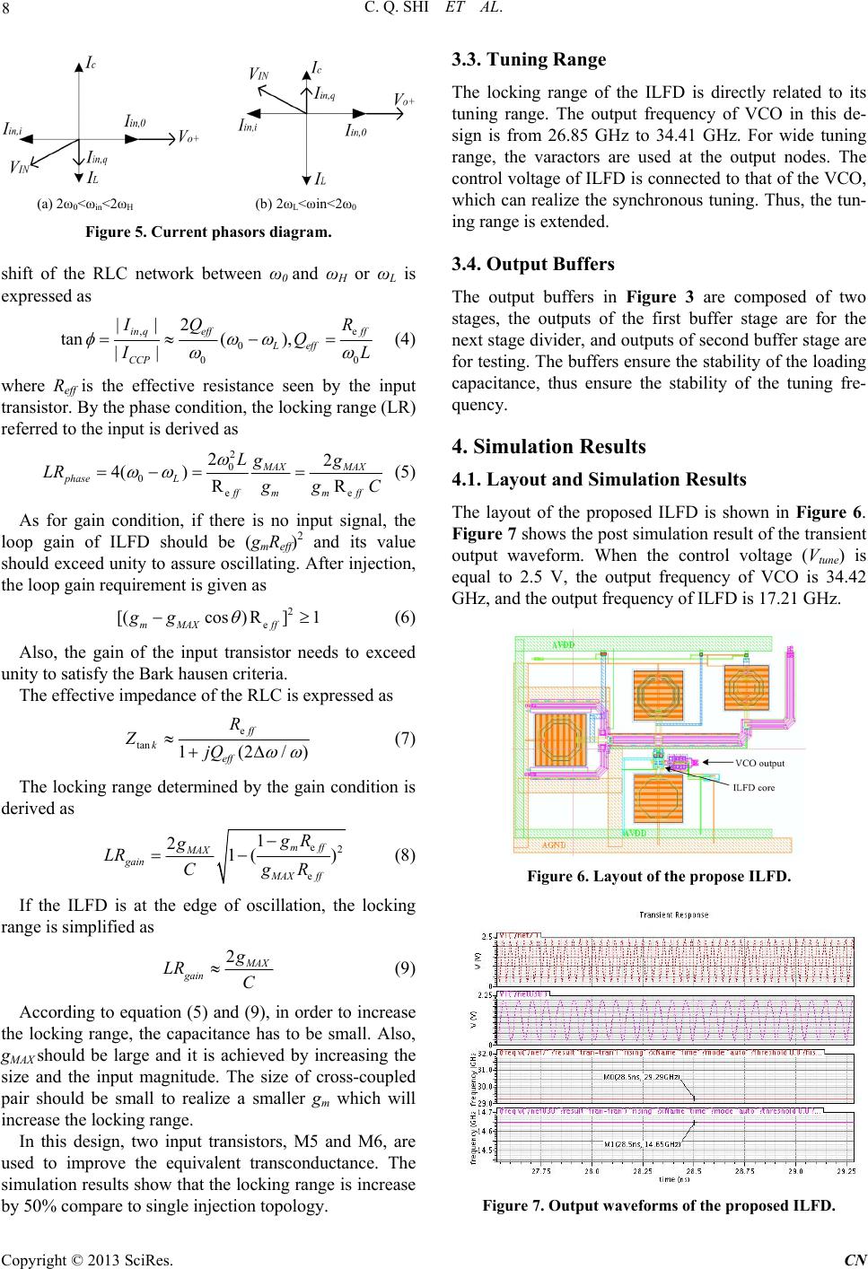 C. Q. SHI ET AL. 8 (a) 2ω0<ωin<2ωH (b) 2ωL<ωin<2ω0 Figure 5. Current phasors diagram. shift of the RLC network between ω0 and ωH or ωL is expressed as , 0 0 ||2 tan( ), || in qeffff Leff CCP e 0 I Q QR I L (4) where Reff is the effective resistance seen by the input transistor. By the phase condition, the locking range (LR) referred to the input is derived as 2 0 0 e 22 4() R MAX MAX phase L ffmm ff Lgg LR e R g gC (5) As for gain condition, if there is no input signal, the loop gain of ILFD should be (gmReff)2 and its value should exceed unity to assure oscillating. After injection, the loop gain requirement is given as 2 e [(cos) R]1 mMAX ff gg (6) Also, the gain of the input transistor needs to exceed unity to satisfy the Bark hausen criteria. The effective impedance of the RLC is expressed as e tan 1(2/ ff k eff R ZjQ ) (7) The locking range determined by the gain condition is derived as e2 e 1 21( ) mff MAX gain MAX ff gR g LR CgR (8) If the ILFD is at the edge of oscillation, the locking range is simplified as 2 M AX gain g LR C (9) According to equation (5) and (9), in order to increase the locking range, the capacitance has to be small. Also, gMAX should be large and it is achieved by increasing the size and the input magnitude. The size of cross-coupled pair should be small to realize a smaller gm which will increase the locking range. In this design, two input transistors, M5 and M6, are used to improve the equivalent transconductance. The simulation results show that the locking range is increase by 50% compare to single injection topology. 3.3. Tuning Range The locking range of the ILFD is directly related to its tuning range. The output frequency of VCO in this de- sign is from 26.85 GHz to 34.41 GHz. For wide tuning range, the varactors are used at the output nodes. The control voltage of ILFD is connected to that of the VCO, which can realize the synchronous tuning. Thus, the tun- ing range is extended. 3.4. Output Buffers The output buffers in Figure 3 are composed of two stages, the outputs of the first buffer stage are for the next stage divider, and outputs of second buffer stage are for testing. The buffers ensure the stability of the loading capacitance, thus ensure the stability of the tuning fre- quency. 4. Simulation Results 4.1. Layout and Simulation Results The layout of the proposed ILFD is shown in Figure 6. Figure 7 shows the post simulation result of the transient output waveform. When the control voltage (Vtune) is equal to 2.5 V, the output frequency of VCO is 34.42 GHz, and the output frequency of ILFD is 17.21 GHz. Figure 6. Layout of the propose ILFD. Figure 7. Output waveforms of the proposed ILFD. Copyright © 2013 SciRes. CN 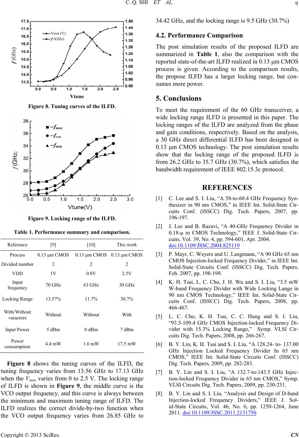 C. Q. SHI ET AL. 9 Figure 8. Tuning curves of the ILFD. Figure 9. Locking range of the ILFD. Table 1. Performance summary and comparison. Reference [9] [10] This work Process 0.13 μm CMOS 0.13 μm CMOS 0.13 μm CMOS Divided number 2 2 2 VDD 1V 0.8V 2.5V Input frequency 70 GHz 63 GHz 30 GHz Locking Range 13.57% 11.7% 30.7% With/Without varactors Without Without With Input Power5 dBm 0 dBm 7 dBm Power consumption 4.4 mW 1.6 mW 17.5 mW Figure 8 shows the tuning curves of the ILFD, the tuning frequency varies from 13.56 GHz to 17.13 GHz when the Vtune varies from 0 to 2.5 V. The locking range of ILFD is shown in Figure 9, the middle curve is the VCO output frequency, and this curve is always between the minimum and maximum tuning range of ILFD. The ILFD realizes the correct divide-by-two function when the VCO output frequency varies from 26.85 GHz to 34.42 GHz, and the locking range is 9.5 GHz (30.7%) 4.2. Performance Comparison The post simulation results of the proposed ILFD are summarized in Table 1, also the comparison with the reported state-of-the-art ILFD realized in 0.13 μm CMOS process is given. According to the comparison results, the propose ILFD has a larger locking range, but con- sumes more power. 5. Conclusions To meet the requirement of the 60 GHz transceiver, a wide locking range ILFD is presented in this paper. The locking ranges of the ILFD are analyzed from the phase and gain conditions, respectively. Based on the analysis, a 30 GHz direct differential ILFD has been designed in 0.13 μm CMOS technology. The post simulation results show that the locking range of the proposed ILFD is from 26.2 GHz to 35.7 GHz (30.7%), which satisfies the bandwidth requirement of IEEE 802.15.3c protocol. REFERENCES [1] C. Lee and S. I. Liu, “A 58-to-60.4 GHz Frequency Syn- thesizer in 90 nm CMOS,” in IEEE Int. Solid-State Cir- cuits Conf. (ISSCC) Dig. Tech. Papers, 2007, pp. 196-197. [2] J. Lee and B. Razavi, “A 40-GHz Frequency Divider in 0.18-μ m CMOS Technology,” IEEE J. Solid-State Cir- cuits, Vol. 39, No. 4, pp. 594-601, Apr. 2004. doi:10.1109/JSSC.2004.825119 [3] P. Mayr, C. Weyers and U. Langmann, “A 90 GHz 65 nm CMOS Injection-locked Frequency Divider,” in IEEE Int. Solid-State Circuits Conf. (ISSCC) Dig. Tech. Papers, Feb. 2007, pp. 198-199. [4] K. H. Tsai, L. C. Cho, J. H. Wu and S. I. Liu, “3.5 mW W-band Frequency Divider with Wide Locking Lange in 90 nm CMOS Technology,” IEEE Int. Solid-State Cir- cuits Conf. (ISSCC) Dig. Tech. Papers, 2008, pp. 466-467. [5] L. C. Cho, K. H. Tsai, C. C. Hung and S. I. Liu, “93.5-109.4 GHz CMOS Injection-locked Frequency Di- vider with 15.3% Locking Range,” Symp. VLSI Cir- cuits Dig. Tech. Papers, 2008, pp. 266-267. [6] B. Y. Lin, K. H. Tsai and S. I. Liu, “A 128.24- to- 137.00 GHz Injection Locked Frequency Divider In 65 nm CMOS,” IEEE Int. Solid-State Circuits Conf. (ISSCC) Dig. Tech. Papers, 2009, pp. 282-283. [7] B. Y. Lin and S. I. Liu, “A 132.7-to-143.5 GHz Injec- tion-locked Frequency Divider in 65 nm CMOS,” Symp. VLSI Circuits Dig. Tech. Papers, 2009, pp. 230-231. [8] B. Y. Lin and S. I. Liu, “Analysis and Design of D-band Injection-locked Frequency Dividers,” IEEE J. Sol- id-State Circuits, Vol. 46, No. 6, pp. 1250-1264, June 2011. doi:10.1109/JSSC.2011.2131750 Copyright © 2013 SciRes. CN  C. Q. SHI ET AL. Copyright © 2013 SciRes. CN 10 [9] C. Y. Wu and C. Y. Yu, “Design and Analysis of Milli- meter-wave Direct Injection-locked Frequency Divider with Large Frequency Locking Range,” IEEE Transac- tions on Microwave Theory and Techniques, Vol. 55, No. 8, 2007, pp. 1649-1658. doi:10.1109/TMTT.2007.902067 [10] S. J. Rong, W. L. Alan and H. C. Luong, “0.9 mW 7 GHz and 1.6 mW 60 GHz Frequency Dividers with Lock- ing-range Enhancement in 0.13 μm CMOS,” IEEE Int. Solid-State Circuits Conf. (ISSCC) Dig. Tech. Papers, 2009, pp. 96-97. |