

Paper Menu >>
Journal Menu >>
 Communications and Network, 2013, 5, 25-28 doi:10.4236/cn.2013.51B007 Published Online February 2013 (http://www.scirp.org/journal/cn) A Smart Home System Design Based on GSM Rongrong Zhang, Xiaoping Zou, Wenhui Huang, Qimu-Surong Beijing Key Laboratory for Sensor, Beijing Information Science and Technology University, Beijing, China Email: [email protected] Received 2012 ABSTRACT This paper introduces a mobile phone short message control method in smart home based on GSM (Global System for Mobile communications). AT commands and the system structure is illustrated in detail. The hardware system including STC89C51 and TC35i is presented. The software framework is also analyzed clearly in this paper. In addition, some other potential application areas and its direction of development in future are given at last. Keywords: GSM; Smart Home; STC89C51; Wireless Communication 1. Introduction As the prevailing trend of IOT (Internet of Things) [1] covering the glob al, smart home find its way in the trend. All control and communication method dashed into this area: GSM, WIFI, CAN, Bluetooth, ZigBee. They all try to solve those problems in this smart world [2]. Among these solutions, GSM has a prominent po sition as mobile phone has been a comprehensive communicating fashion in modern society. GSM is a kind of digital mobile communication net- work. It is developing rapidly in recent years. And the short message service is an important business network based on GSM. Its simple and efficient performance as well as relatively low fee absorbs the customers. [3] Moreover, the technical possibility for many types of remote monitoring make it bound to be the most conven- ient and welcomed way in smart home control as people can monitor their home anytime anywhere. In this paper, I’ll present you a wonderful smart home solution based on GSM and explain the implementation of software and hardware. 2. System Framework The GSM control system contains the communication part, the control center and the object to be controlled. Figure 1 is the system block diagram. In this system, GSM module plays the communication role. STC89C516RD+ bears the task of a control center. The relay module connected to home appliances is the object to be controlled. There are several channels of relays on the module. Each connects to a different home appliance. The GSM module with a smart card is responsible for receiving text messages from the GSM network and transmitting the short message from the local MCU (STC89C516RD+) to the GSM network. It also receives message command from user’s mobile and sends the cor- responding command to the control center STC89C- 516RD+. The controller analysis the command and con- ducts the relay to open or close the anticipated cannel, such to open or close the related appliance. After this, the control center indicates the GSM module to send feed- back message to the user terminal. 3. AT Commands MCU communicate with GSM module through AT (At- tention Commands) [4]. AT command set is the interface standard between TE (terminal equipment) and TA (ter- minal adaptor), as well as between DTE (data terminal equipment) and DCE (data circuit terminal equipment). In the early 1990s, AT command set is only used in the operation of modem. With a series of evolution, AT commands are added GSM07.05 standards. Up to now, Most of the GSM modules support this standard. 3.1. The Syntax of Basic AT Commands Each AT command must begin with “AT” or “at”, and end with <CR>. Four kinds of syntax are showed in Ta - ble l. Figure 1. The block diagram of the mobile control system. Copyright © 2013 SciRes. CN 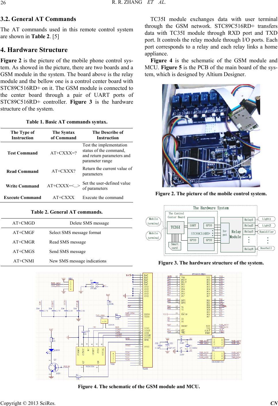 R. R. ZHANG ET AL. 26 3.2. General AT Commands The AT commands used in this remote control system are shown in Table 2. [5] 4. Hardware Structure Figure 2 is the picture of the mobile phone control sys- tem. As show ed in th e p ictur e, th ere are two bo ards and a GSM module in the system. The board above is the relay module and the bellow one is a control center board with STC89C516RD+ on it. The GSM module is connected to the center board through a pair of UART ports of STC89C516RD+ controller. Figure 3 is the hardware structure of the system. Table 1. Basic AT commands syntax. The Type of Instruction The Syntax of Command The Describe of Instruction Test Command AT+CXXX=? Test the implementation status of the command, and return parameters and parameter rang e Read Command AT+CXXX? Return the current value of parameters Write Command AT+CXXX=<...> Set the user-defined value of parameters Execute Command AT+CXXX Execute the command Table 2. General AT commands. AT+CMGD Delete SMS message AT+CMGF Select SMS message format AT+CMGR Read SMS message AT+CMGS Send SMS message AT+CNMI New SMS message indications TC35I module exchanges data with user terminal through the GSM network. STC89C516RD+ transfers data with TC35I module through RXD port and TXD port. It controls the relay module through I/O ports. Each port corresponds to a relay and each relay links a home appliance. Figure 4 is the schematic of the GSM module and MCU. Figure 5 is the PCB of the main board of the sys- tem, which is designed by Altium Designer. Figure 2. The picture of the mobile control system. Figure 3. The hardware structure of the system. Figure 4. The schematic of the GSM module and MCU. Copyright © 2013 SciRes. CN 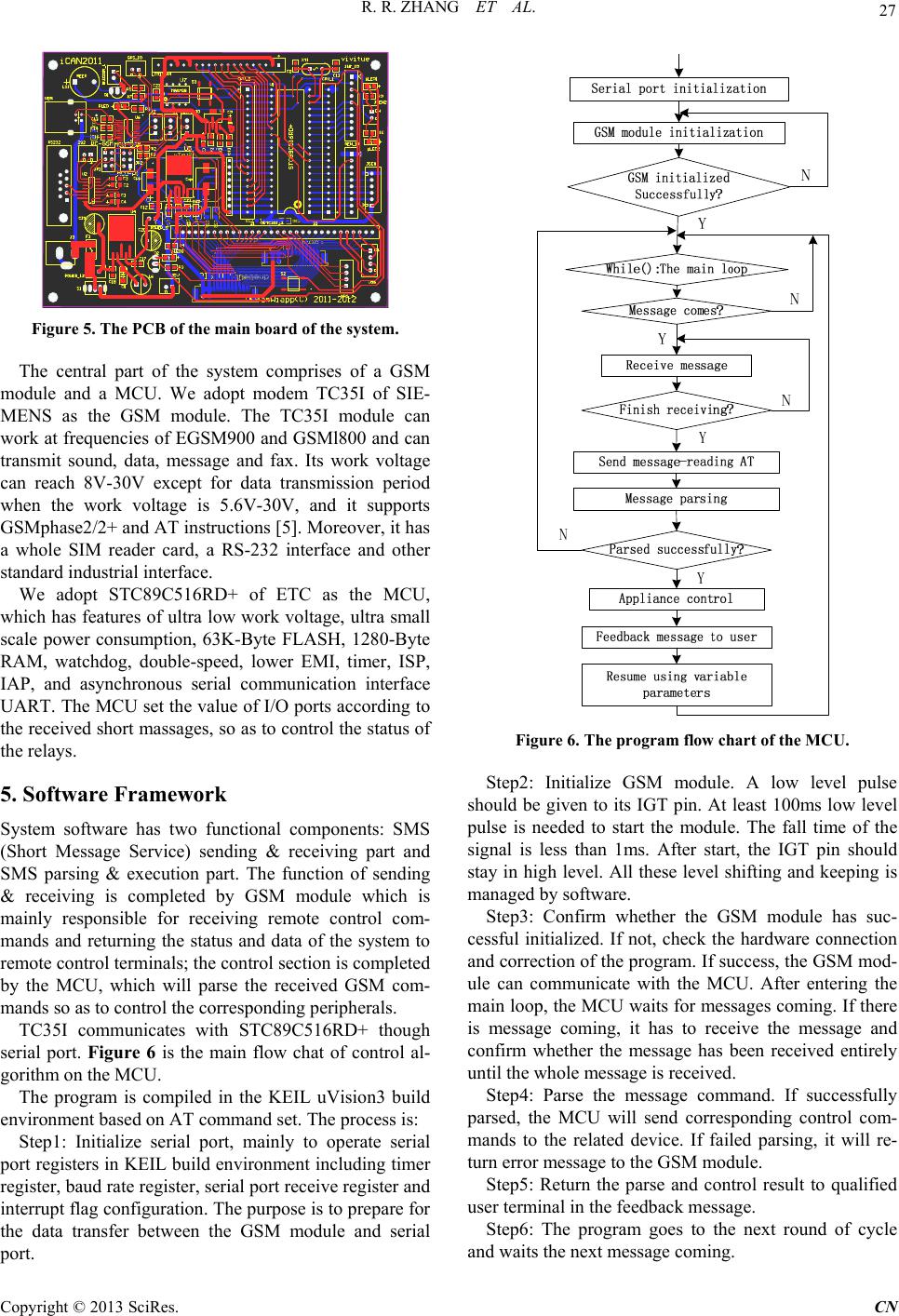 R. R. ZHANG ET AL. 27 3 2 10 2 1 21 2 1 1 2 1 2 1 22 1 2 4 6 1 3 5 2 1 1 2 4142 4142 6 5 43 2 1 6 5 4 3 2 1 40 39 38 37 36 35 34 33 32 31 30 29 28 27 26 25 24 23 22 20 19 18 17 16 15 14 13 12 11 10 9 8 7 6 5 4 3 21 2 1 20 19 1817 16 15 1413 12 1110 987654321 1 2 3 4 5 6 7 8 9 10 11 12 13 14 15 16 17 18 19 20 20 19 18 17 16 15 14 13 12 11 10 9 8 7 6 5 4 3 2 1 3 2 5 4 1 6 3 3 3 3 2 222 3 2 1 1 1 1 1 12 8 7 6 5 4 1 2 3 9 10 8 7 6 5 4 1 2 3 9 10 2 1 2 1 1 532 5 4 12 1 2 1 2 3 2 1 4 5 6 2 1 3 2 1 2 1 1 2 2 1 1 2 1 2 2 1 2 1 12 2 1 1 2 1 2 1 2 1 2 2 1 12 1 2 2 1 12 2 1 2 1 1 2 1 2 21 1 2 3 2 1 2 1 3 2 1 8 7 6 5 4 3 2 1 9 1 2 132 3 1 2 12 2 1 12 1 2 12 1 2 1 2 5678 1 2 34 1 2 8 7 6 4 3 2 5 1 9 10 11 23 1 4 3 2 1 54321 6 14 23 3 2 4 1 16 15 14 13 12 11 10 8 7 6 5 4 3 2 1 9 10 11 12 13 14 15 16 214 53 15 1 2 3 4 5 6 7 8 9 10 11 12 13 14 16 17 18 19 20 21 22 23 24 25 26 27 28 4 1 2 3 1 2 21 1 2 2 1 12 1121 12 1314 1516 17 1819 2021 22 2324 25 26 2728 29 3031 32 33 3435 36 3738 3940 1 2 1 2 12 12 A K Figure 5. The PCB of the main board of the system. The central part of the system comprises of a GSM module and a MCU. We adopt modem TC35I of SIE- MENS as the GSM module. The TC35I module can work at frequencies of EGSM900 and GSMl800 and can transmit sound, data, message and fax. Its work voltage can reach 8V-30V except for data transmission period when the work voltage is 5.6V-30V, and it supports GSMphase2/2+ and AT instructions [5]. Moreov er, it has a whole SIM reader card, a RS-232 interface and other standard industrial interface. We adopt STC89C516RD+ of ETC as the MCU, which has features of ultra low work voltage, ultra small scale power consumption, 63K-Byte FLASH, 1280-Byte RAM, watchdog, double-speed, lower EMI, timer, ISP, IAP, and asynchronous serial communication interface UART. The MCU set the value of I/O ports according to the received short massages, so as to control the status of the relays. 5. Software Framework System software has two functional components: SMS (Short Message Service) sending & receiving part and SMS parsing & execution part. The function of sending & receiving is completed by GSM module which is mainly responsible for receiving remote control com- mands and returning the status and data of the system to remote control terminals; the control section is completed by the MCU, which will parse the received GSM com- mands so as to control the corresponding peripherals. TC35I communicates with STC89C516RD+ though serial port. Figure 6 is the main flow chat of control al- gorithm on the MCU. The program is compiled in the KEIL uVision3 build environment based on AT command set. The process is: Step1: Initialize serial port, mainly to operate serial port registers in KEIL build environment including timer register, baud rate register, serial port receive register and interrupt flag configur ation. The purpose is to prepare for the data transfer between the GSM module and serial port. Figure 6. The program flow chart of the MCU. Step2: Initialize GSM module. A low level pulse should be given to its IGT pin. At least 100ms low level pulse is needed to start the module. The fall time of the signal is less than 1ms. After start, the IGT pin should stay in high level. All these level shifting and keeping is managed by software. Step3: Confirm whether the GSM module has suc- cessful initialized. If not, check the hardware connection and correction of the program. If success, the GSM mod- ule can communicate with the MCU. After entering the main loop, the MCU waits for messages coming. If there is message coming, it has to receive the message and confirm whether the message has been received entirely until the whole message is received . Step4: Parse the message command. If successfully parsed, the MCU will send corresponding control com- mands to the related device. If failed parsing, it will re- turn error message to the GSM module. Step5: Return the parse and control result to qualified user terminal in the feedback message. Step6: The program goes to the next round of cycle and waits the next message coming. Copyright © 2013 SciRes. CN  R. R. ZHANG ET AL. 28 6. Software Tests and Results Discussion The qualified mobile phone can send prescriptive text messages remotely to control the work status of home appliances. When we edit a message “open1” and send to the SIM card number of the GSM module, the light on channel1 is illuminated. Then we receive a feedback message from the system indicating “Light 1 opened!” When we send a message “close1” to the system, the light will be extinguished and a feedback message is send to the mobile phone. If we use other commands (pre- scribed in the program) like “open2”, “open3”…other appliance will be opened. In this way, we realize the function to control home appliances at any place the GSM networ k cov ered. 7. Conclusions and Prospect This system makes remote control available based on GSM with low cost hardware and low consumption. The design is not merely a good smart home solution. It makes sense in industry control and other fields. Al- though it’s a simple solution, it indicates the technology trend of smart world. In our future research, more tech- nology will be added to the system. For example, sensor module, which can collect parameters like temperature and humidity as references for relevant appliance con- trolling. With the fast development of mobile phone hardware and software, embedding accessional software in mobile phone will be possible as mobile p hone tends to be like a mini computer. In the near future, we can monitor and control our home appliances through the multimedia ap- plication software on our mobile phone. There will be video, sound or word messages interact with smart home devices [1]. The prospect of mobile phone control system is bright with no doubt. 8. Acknowledgements This work has been partially funded by the Program of Beijing Key Lab for Sensor under Grant No.KF2011 1077205. REFERENCES [1] Neil Gershenfeld, Raffi Krikorian, Danny Cohen, “The Internet of Things,” Scientific American, Vol. 91, 2004, pp. 76-81. doi:10.1038/scientificamerican1004-76 [2] J. Yick, B. Mukherjee and D. Ghosal, “Wireless Sensor Network Survey,” Computer Networks, Vol. 52, 2008, pp. 2297-2230. doi:10.1016/j.comnet.2008.04.002 [3] Q. W. Sun and Z. Yu, “An SMS Alarm Processing Scheme in GSM,” Journal of Fuzhou University (Natural Science), Vol. 36, 2008. [4] E. Zhou, “A Remote Measurement and Control System based on GSM-SMS,” Sci/Tech Information Development & Economy, Vol. 11, No. 5, 2001. [5] Siemens Cellular Engine, TC35i Terminal Datasheet, TC35i_ATC_V02. 07, 2007. Copyright © 2013 SciRes. CN |