

Paper Menu >>
Journal Menu >>
 Journal of Applied Mathematics and Physics, 2013, 1, 45-50 http://dx.doi.org/10.4236/jamp.2013.14009 Published Online October 2013 (http://www.scirp.org/journal/jamp) Copyright © 2013 SciRes. JAMP Modeling of the Behavior of a Deep Groove Ball Bearing in Its Housing Ayao E. Azianou1 ,2, Karl Debray1, Fabrice Bolaers1, Philippe Chiozzi2, Frédéric Pall eschi2 1Groupe de Recherche en Sciences de l’Ingénieur, Université de Reims Champagne Ardenne, EA 4694 URCA, Moulin de la Housse, 51687 Reims Cedex 2, France 2Valeo Electric Systems, 2 Rue André Boulle, 94000 Créteil, France Email: a.a [email protected], karl.debray@univ-reims.fr Received August 2013 ABSTRACT Load distribution in deep groove ball bearing has been studied in this work. A deep groove ball bearing model is pro- posed basing on geometry specific measurement. Two approaches (finite element method and semi-analytical) have been used to determine the distribution of an external radial force applied. These two approaches have been compared in terms of computation time and precision. At the second point, a deformable complex bearing housing has been inte- grated in the FEM ball bearing model to assess the influence of its deformation on load distribution. Keywords: Ball Bearing; Finite Element; Semi-Analytical; Load Distribution; Housing 1. Introduction Automotive alternators are rotating machines whose main role is to convert the mechanical energy of rotation into electrical energy for powering electrical and elec- tronic components of the car. With the evolution of technology, new generations of alternators have been developed. These alternators have complex shapes and are equipped with stop-and-start systems to reduce noise, fuel consumption and the emission of greenhouse gases. An alternator is mainly composed of a stator and a rotor guided in rotation by two ball bearings. The transfer of loads from one ring to another is possible by means of the balls in contact with the rings. Load distribution in bearings is an important factor in the proper functioning of the ball bearing and its fatigue lifetime estimation. Depending on the type of external load, all the balls don’t have the same contribution to the load transfer. Another important parameter involved in the load distribution is the internal clearance within the ball bearing. Several authors have worked on load distribution problem. The first work was done by Stribeck [1] for external radial loading. He has determined in his formu- lation the maximum force on a ball. Although this for- mulation has been used for a long time to calculate the static bearing capacity, it do es not explicitly consider the value of the clearance. Sjovall [2] established a formula- tion taking into account the value of the clearance where the maximum force is a function of an integral that holds his name. Jones [3], based on the Hertz contact theory [4] pro- posed an analytical approach to determine the relative motion of the rolling over rings. This approach was im- proved by Harris and was called Jones-Harris method (JHM) [5]. The relative displacements at the contact ball- rings due to external forces were determined by Newton- Raphson method. From the relation between force and displacement, the forces are obtained from the displace- ments o btained by Hertz formulation. Other authors used Finite Element Method (FEM) to solve the problems of contact within the bearing and determine load distribu- tion. By using the finite element method to determine coefficients used in load-displacement relation, Yuan Kang et al. [6] modified the method of Jones-H ar - ris which was called modified Jones-Harris method (MJHM). Bourdon et al. [7] replaced, in a modeling of deep groove ball bearings, balls by specific elements to study the bearing behavior. Most of these studies considered that the bearings are mounted in a rigid housing. This assumption is not rea- listic when we consider the case of a new generation of alternator where the housing is complex and deformable. This paper assesses the influence of housing deformation on load distribution in the bearing by two different ap- proaches: a finite element approach and a semi-analytical approach where the rolling elements are replaced by user elements. A prior study has been done by using these two approaches in the case of rigid housing. The geometry of ball bearing is important in load dis- tribution modeling, especially curvature radii of the 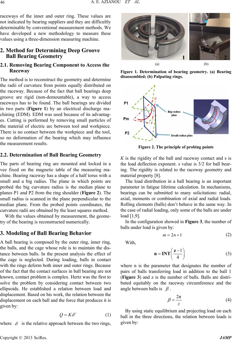 A. E. AZIANOU ET AL. Copyright © 2013 SciRes. JAMP 46 raceways of the inner and outer ring. These values are not indicated by bearing suppliers an d they are difficultly determinable by conventional measurement methods. We have developed a new methodology to measure these values using a three-dimension measuring machine. 2. Method for Determining Deep Groove Ball Bearing Geometry 2.1. Removing Bearing Component to Access the Raceway The method is to reconstruct the geometry and determine the radii of curvature from points equally distributed on the raceway. Because of the fact that ball bearings deep groove are rigid (non-demountable), a way to access raceways has to be found. The ball bearings are divided in two parts (Figure 1) by an electrical discharge ma- chining (EDM). EDM was used because of its advantag- es. Cutting is performed by removing small particles of the material of electric arc between tool and workpiece. There is no contact between the workpiece and the tool, so no deformation of the bearing which may influence the measurement results. 2.2. Determination of Ball Bearing Geometry The parts of bearing ring are mounted and locked in a vee fixed on the magnetic table of the measuring ma- chine. Bearing raceway has a shape of a h alf torus with a small and a big radius. The plane in which points are probed the big curvature radius is the median plane to planes P1 and P2 from the ring shoulder (Figure 2) . The small radius is scanned in the plane perpendicular to the median plane. From the probed points coordinates, the curvature radii are obtained by the least squares method. With the values obtained by measurement, the geome- try of the bearing is reconstructed numerically. 3. Modeling of Ball Bearing Behavior A ball bearing is composed by the outer ring, inner ring, the balls, and the cage whose role is to maintain the dis- tance between balls. In the present analysis the effect of the cage is neglected. During loading, balls in contact with the rings deform both inner and outer rings. Because of the fact that the contact surfaces in ball bearing are not known, contact pro blem is complex. Her tz was the first to solve the problem by considering contact between two ellipsoids. He established a relation between load and displacement. Based on his work, the relation between the displacement on each ball and the force that produces it is given by: s QK δ = (1) where δ is the relative approach between the two rings, (a) (b) Figure 1. Determination of bearing geometry. (a) Bearing disassembled; (b) Palpating rings. Figure 2. The principle of probing points K is the rigidity of the ball and raceway contact and s is the load deflection exponent. s value is 3/2 for ball bear- ing. The rigidity is related to the raceway geometry and material property [8]. The load distribution in a ball bearing is an important parameter in fatigue lifetime calculation. In mechanisms, bearings can be submitted to many solicitations: radial, axial, moments or combination of axial and radial loads. Rolling elements (balls) don’t behave in the same way. In the case of r a di a l loading, only s ome of the balls a r e unde r load [1,9]. In the configuration showed in Figure 3, the number of balls under l oad is given by: 21mn= + (2) With, 1 4 − = z n INT (3) where n is the parameter that designates the number of pairs of balls transferring load in addition to the ball 1 (Figure 3) and z is the number of balls. Balls are distri- buted equitably on the raceway circumference and the angle between balls is β . 2π z β = (4) By using static equilibrium and projecting load on each ball in the three directions, the relation between loads is given by: 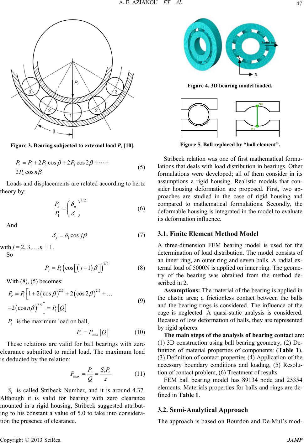 A. E. AZIANOU ET AL. Copyright © 2013 SciRes. JAMP 47 Figure 3. Bearing subjected to external load Pr [10]. 12 3 2cos2 cos2 2 cos r n PP PP Pn ββ β =+ +++ (5) Loads and displacements are related according to hertz theory by: 3/2 11 nn P P δ δ = (6) And 1 cos j j δδ β = (7) with j = 2, 3,…,n + 1. So ( ) ( ) 3/2 1 cos 1 j PP j β = − (8) With (8), (5) becomes: ( )() ( ) [ ] 2.5 2.5 1 2.5 1 12 cos2 cos2 2 cos r PP n PQ ββ β = +++… += (9) 1 P is the maximum load on ba ll, [ ] maxr PPQ= (10) These relations are valid for ball bearings with zero clearance submitted to radial load. The maximum load is deducted by the relation: max tr rSP P PQz = = (11) t S is called Stribeck Number, and it is around 4.37. Although it is valid for bearing with zero clearance mounted in a rigid housing, Stribeck suggested attribut- ing to his constant a value of 5.0 to take into considera- tion the presence of clearance. Figure 4. 3D bearing model loaded. Figure 5. Ball replaced by “ball element”. Stribeck relation was one of first mathematical formu- lations that d eals with load distribution in bearings. Other formulations were developed; all of them consider in its assumptions a rigid housing. Realistic models that con- sider housing deformation are proposed. First, two ap- proaches are studied in the case of rigid housing and compared to mathematical formulations. Secondly, the deformable housing is integrated in the model to evaluate its deformation influenc e . 3.1. Finite Element Method Model A three-dimension FEM bearing model is used for the determination of load distribution. The model consists of an inner ring, an outer ring and seven balls. A radial ex- ternal load of 5000N is applied on inner ring. The geome- try of the bearing was obtained from the method de- scribed in 2 . Assumptions: The material of the bearing is applied in the elastic area; a frictionless contact between the balls and the bearing rings is considered. The influence of the cage is neglected. A quasi-static analysis is considered. Because of low deformation of balls, they are represented by rigid spheres. The main steps of the analysis of bearing contact are: (1) 3D construction using ball bearing geometry, (2) De- finition of material properties of components: (Table 1), (3) Definition of contact properties (4) Application of the necessary boundary conditions and loading, (5) Resolu- tion of contact problem , (6) T r e a tment of results. FEM ball bearing model has 89134 node and 25354 elements. Materials properties for balls and rings are de- fined in Table 1. 3.2. Semi-Analytical Approach The approach is based on Bourdon and De Mul’s mod- 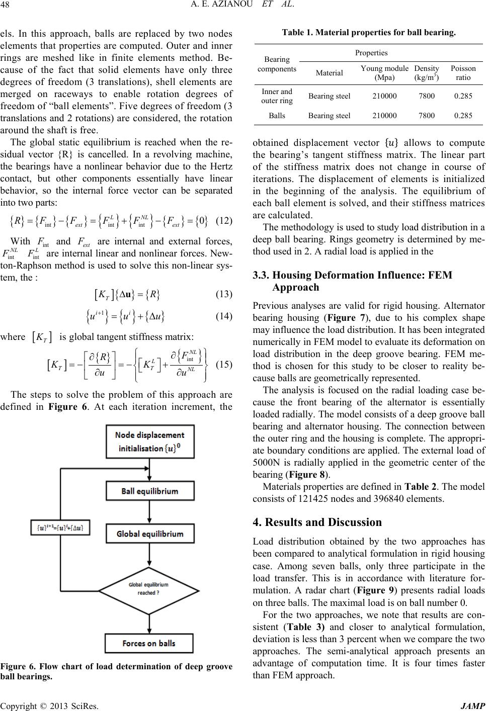 A. E. AZIANOU ET AL. Copyright © 2013 SciRes. JAMP 48 els. In this approach, balls are replaced by two nodes elements that proper ties are computed. Outer and inner rings are meshed like in finite elements method. Be- cause of the fact that solid elements have only three degrees of freedom (3 translations), shell elements are merged on raceways to enable rotation degrees of freedom of “ball elements”. Five degrees of freedom (3 translations and 2 rotations) are considered, the rotation around the shaft is fr ee. The global static equilibrium is reached when the re- sidual vector {R} is cancelled. In a revolving machine, the bearings have a nonlinear behavior due to the Hertz contact, but other components essentially have linear behavior, so the internal force vector can be separated into two parts: { } {} {} {} {} { } { } intint int 0 L NL ext ext RF FF FF=−=+ −= (12) With int F and ext F are internal and external forces, int NL F int L F are internal linear and nonlinear forces. New- ton-Raphson method is used to solve this non-linear sys- tem, the : [ ] {}{ } T KR∆=u (13 ) {}{ } { } 1ii uuu + = +∆ (14) where [ ] T K is global tangent stiffness matrix: [ ] { } { } int NL L TT NL F R KK uu ∂ ∂ =− =−+ ∂∂ (15) The steps to solve the problem of this approach are defined in Figure 6. At each iteration increment, the Figure 6. Flow chart of load determination of deep groove ball bear i ngs. Table 1. Material properties for ball bearing. Bearing components Properties Material Young module (Mpa) Density (kg/m3) Poisson ratio Inner and outer ring Bearing steel 210000 7800 0.285 Balls Bearing steel 210000 7800 0.285 obtained displacement vector {} allows to compute the bearing’s tangent stiffness matrix. The linear part of the stiffness matrix does not change in course of iterations. The displacement of elements is initialized in the beginning of the analysis. The equilibrium of each ball element is solved, an d their stiffn ess matrices are calcula ted. The methodology is used to study load distribution in a deep ball bearing. Rings geometry is determined by me- thod used in 2. A radial load is applied in the 3.3. Housing Deformation Influence: FEM Approach Previous analyses are valid for rigid housing. Alternator bearing housing (Figure 7), due to his complex shape may influence the load distribution. It has been integrated numerically in FEM model to evaluate its deformation on load distribution in the deep groove bearing. FEM me- thod is chosen for this study to be closer to reality be- cause balls are geometrically represented. The analysis is focused on the radial loading case be- cause the front bearing of the alternator is essentially loaded radially. The model consists of a deep groove ball bearing and alternator housing. The connection between the outer ring and the housing is complete. The appropri- ate boundary conditions are applied. The external load of 5000N is radially applied in the geometric center of the bearing (Figure 8). Materials properties ar e defined in Tab le 2. The model consist s of 12 1425 nodes and 39 6840 element s . 4. Results and Discussion Load distribution obtained by the two approaches has been compared to analytical formulation in rigid housing case. Among seven balls, only three participate in the load transfer. This is in accordance with literature for- mulation. A radar chart (Figure 9) presents radial loads on three balls. The maximal load is on ball number 0. For the two approaches, we note that results are con- sistent (Table 3) and closer to analytical formulation, deviation is less than 3 percent when we compare the two approaches. The semi-analytical approach presents an advantage of computation time. It is four times faster than FEM approach. 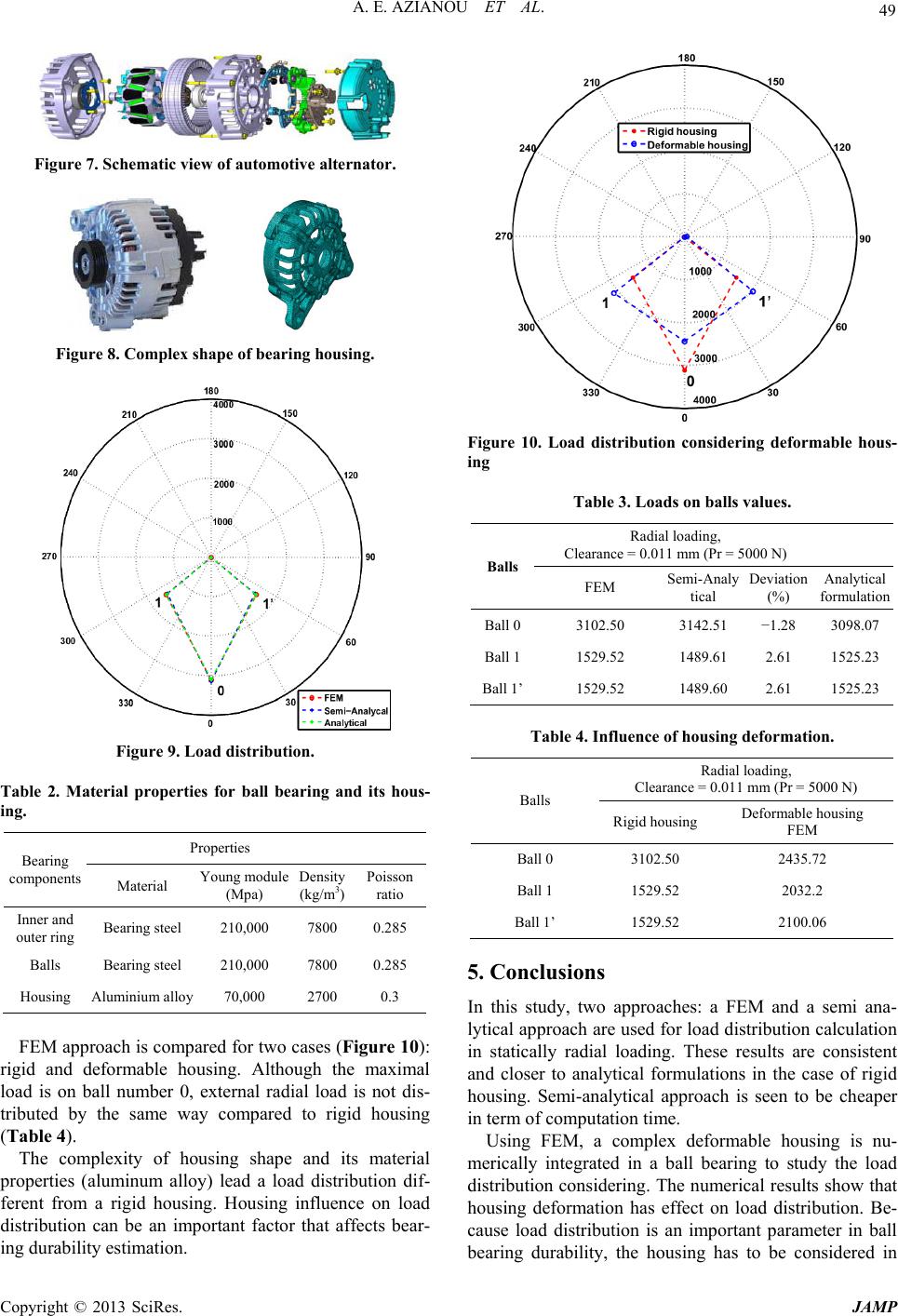 A. E. AZIANOU ET AL. Copyright © 2013 SciRes. JAMP 49 Figure 7. Schematic view of automotive alternator. Figure 8. Complex shape of bearing hou s i ng. Figure 9. Load distribution. Table 2. Material properties for ball bearing and its hous- ing. Bearing components Properties Material Young module (Mpa) Density (kg/m3) Poisson ratio Inner and outer ring Bearing steel 210,000 7800 0.285 Balls Bearing steel 210,000 7800 0.285 Housing Aluminium alloy 70,000 2700 0.3 FEM approach is compared for two cases (Figu re 10): rigid and deformable housing. Although the maximal load is on ball number 0, external radial load is not dis- tributed by the same way compared to rigid housing (Table 4). The complexity of housing shape and its material properties (aluminum alloy) lead a load distribution dif- ferent from a rigid housing. Housing influence on load distribution can be an important factor that affects bear- ing durability estimation. Figure 10. Load distribution considering deformable hous- ing Table 3. Loads on balls values. Balls Radial loading, Clearance = 0.011 mm (Pr = 5000 N) FEM Semi-Analy tical Deviation (%) Analytical formulation Ball 0 3102.50 3142.51 −1.28 3098.07 Ball 1 1529.52 1489.61 2.61 1525.23 Ball 1’ 1529.52 1489.60 2.61 1525.23 Table 4. Influence of housing deformation. Balls Radial loading, Clearance = 0.011 mm (Pr = 5000 N) Rigid housi ng Deformable housing FEM Ball 0 3102.50 2435.72 Ball 1 1529.52 2032.2 Ball 1’ 1529.52 2100.06 5. Conclusions In this study, two approaches: a FEM and a semi ana- lytical approach are used for load distribution calculation in statically radial loading. These results are consistent and closer to analytical formulations in the case of rigid housing. Semi-analytical approach is seen to be cheaper in term of computation time. Using FEM, a complex deformable housing is nu- merically integrated in a ball bearing to study the load distribution consid ering. The nu merical results sh ow that housing deformation has effect on load distribution. Be- cause load distribution is an important parameter in ball bearing durability, the housing has to be considered in 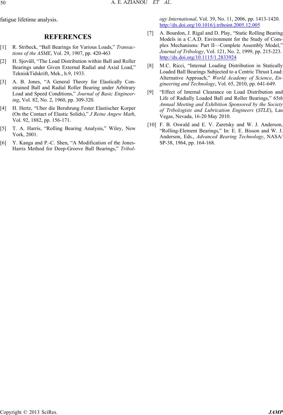 A. E. AZIANOU ET AL. Copyright © 2013 SciRes. JAMP 50 fatigue lifetime analysis. REFERENCES [1] R. Stribeck, “Ball Bearings for Various Loads,” Transac- tions of the ASME, Vol. 29, 1907, pp. 420-463 [2] H. Sjoväll, “The Loa d Distribution within Ball and Roller Bearings under Given External Radial and Axial Load,” TekniskTidskrift, Mek., h.9, 1933. [3] A. B. Jones, “A General Theory for Elastically Con- strained Ball and Radial Roller Bearing under Arbitrary Load and Speed Conditions,” Journal of Basic Engineer- ing, Vol. 82, No. 2, 1960, pp. 309-320. [4] H. Hertz, “Uber die Beruhrung Fester Elastischer Korper (On the Contact of Elastic Solids),” J Reine Angew Math, Vol. 92, 1882, pp. 156-171. [5] T. A. Harris, “Rolling Bearing Analysis,” Wiley, New York, 2001. [6] Y. Kanga and P.-C. Shen, “A Modification of the Jones- Harris Method for D eep-Groove Ball Bearings,” Tribol- ogy International, Vol. 39, No. 11, 2006, pp. 1413-1420. http://dx.doi.org/10.1016/j.triboint.2005.12.005 [7] A. Bourdon, J. Rigal and D. Play, “Static Rolling Bearing Models in a C.A.D. Environment for the Study of Com- plex Mechanisms: Part II—Complete Assembly Model,” Journal of Tribology, Vol. 121, No. 2, 1999, pp. 215-223. http://dx.doi.org/10.1115/1.2833924 [8] M.C. Ricci, “Internal Loading Distribution in Statically Loaded Ball Bearings Subjected to a Centric Thrust Load: Alternative Approach,” World Academy of Science, En- gineering and Technology, Vol. 65, 2010, pp. 641-649. [9] “Effect of Internal Clearance on Load Distribution and Life of Radially Loaded Ball and Roller Bearings,” 65th Annual Meeting and Exhibition Sponsored by the Society of Tribologists and Lubrication Engineers (STLE), Las Vegas, Nevada, 16-20 May 2010. [10] F. B. Oswald and E. V. Zaretsky and W. J. Anderson, “Rolling-Element Bearings,” In: E. E. Bisson and W. J. Anderson, Eds., Advanced Bearing Technology, NASA/ SP-38, 1964, pp. 164-168. |