

Paper Menu >>
Journal Menu >>
 Energy and Power Engineering, 2013, 5, 657-660 doi:10.4236/epe.2013.54B127 Published Online July 2013 (http://www.scirp.org/journal/epe) Research on Con t rol Strategy of 2 - p h a s e Interleaving Magnetic Integrated VRM Rui Guo1,2, Con g Wang 1,Yugang Yang2 1School of Mechanical Electronic & Information Engineering, China University of Mining & Technology, Beijing, China 2Faculty of Electrical and Control Engineering, Liaoning Technical University, Huludao, Liaoning, China Email: [email protected] Received February, 2013 ABSTRACT A kind of 2-phase interleaving coupled magnetic integrated VRM is studied and the corresponding passivity-based con- trol strategy is put forward. The model of this kind of magnetic integrated VRM is constructed, and the performance of this 2-phase interleaving magnetic integrated VRM of passivity-based control is verified by simulation experiments. The results proved that this kind of passivity-based control strategy can decrease the steady state current ripple and the dynamic output voltage under load disturbance. Keywords: VRM; Magnetic Integrated; Interleaving; Coupled Inductors 1. Introduction Nowadays, the topology used in VRM is mostly multi- phase interleaving Buck converter, in which the magnetic components have important effect on the performance of VRM. In order to increase the power density and effi- ciency of VRM, the magnetic integration technology is applied to it [1-3]. However, each phase winding of the multi-phase magnetic integrated VRM has a self induc- tance, meanwhile, it can form coupled magnetic circuit with the other phase windings. Therefore, it is difficult to construct the model of VRM and the traditional linear control methods can not meet the demand of the per- formance [4]. A kind of 2-phase negative coupling mag- netic integrated VRM is studied in this paper and its cir- cuit model is constructed using linear system control theory, what’s more, the corresponding nonlinear passiv- ity-based control strategy is put forward to realize the equality of each phase current and to improve the dy- namic performance of VRM. 2. Model Building of 2-phase Interleaving Magnetic Integrated VRM The model of 2-phase interleaving negative coupled magnetic integrated VRM is shown in Figure 1. There are 4 operation modes in each switch cycle, and the cor- responding equivalent circuits are shown in Figure 2. Supposed that VRM operates in the mode of continu- ous current, and the 4 operating modes of VRM are de- fined as “Σ1”, “Σ2”, “Σ3” and “Σ4”. The state variables are selected as 123 T x x xx, where “x1” and “x3” are cur- rents “i1” and “i2”, “x3” is voltage “uc” , “Lk” is leakage inductance, “k” is coupling coefficient, and “R” is the load resistance. The models of the 4 modes “Σ1”, “Σ2”, “Σ3” and “Σ4” are as follow: 11 22 3 1 00 1 1 :00 0 (12 )0 11 1 1 00 0 1 :00 0 0 11 1 1 00 1 :00 11 1 K in oo KK K oo K K in KK Lk V 1 2 x xA LLk RC RC RC L xxAxb L RC RCRC L V xx LL RC RCRC xb 33 0 1 (12 )0 oo kAxb k *Sponsor: National Natural Science Foundation of China (No. 51177067 and No. 51077125) Copyright © 2013 SciRes. EPE 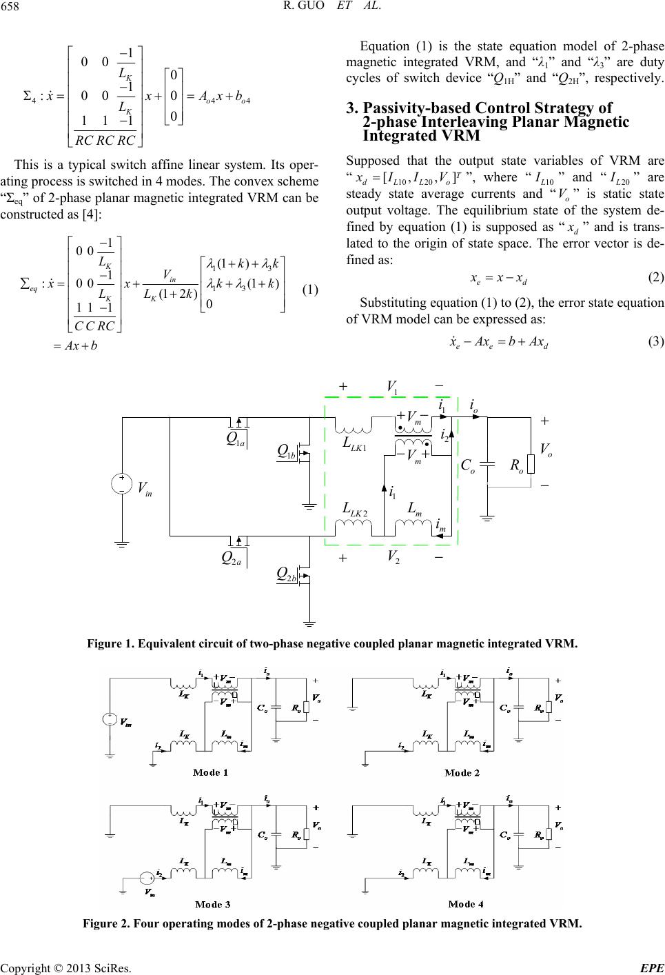 R. GUO ET AL. 658 4 1 00 0 1 :00 0 0 11 1 K oo K L 44 x xAx L RC RCRC b This is a typical switch affine linear system. Its oper- ating process is switched in 4 modes. The convex scheme “Σeq” of 2-phase planar magnetic integrated VRM can be constructed as [4]: 13 13 1 00 (1 ) 1 :00 (1 (12)0 11 1 K in eq KK Lkk V Equation (1) is the state equation model of 2-phase magnetic integrated VRM, and “λ1” and “λ3” are duty cycles of switch device “Q1H” and “Q2H”, respectively. 3. Passivity-based Control Strategy of 2-phase Interleaving Planar Magnetic Integrated VRM ) x xk LLk CCRC Ax b k (1) Supposed that the output state variables of VRM are “10 20 [, ,] T dLLo x IIV ”, where “10 L I ” and “20 L I ” are steady state average currents and “o” is static state output voltage. The equilibrium state of the system de- fined by equation (1) is supposed as “d V x ” and is trans- lated to the origin of state space. The error vector is de- fined as: ed x xx (2) Substituting equation (1) to (2), the error state equation of VRM model can be expressed as: ee d x Axb Ax (3) 1a Q 2a Q 1b Q 2b Q o C o R o V in V m V m V 1 i 2 i o i m i 1 i 1LK L 2LK L m L 1 V 2 V Figure 1. Equivalent circuit of two-phase negative coupled planar magnetic integrated VRM. Figure 2. Four operating modes of 2-phase negative coupled planar magnetic integrated VRM. Copyright © 2013 SciRes. EPE 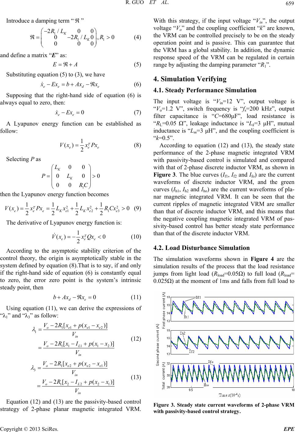 R. GUO ET AL. 659 Introduce a damping term “ ” 1 11 2/0 0 02/0, 000 K K RL RL R 0 A e (4) and define a matrix “E” as: E (5) Substituting equation (5) to (3), we have ee d x Exb Axx (6) Supposing that the right-hand side of equation (6) is always equal to zero, then: 0 ee xEx (7) A Lyapunov energy function can be established as follow: 1 () 2 T ee Vx xPxe 0 (8) Selecting P as 1 00 00 00 K K L PL RC then the Lyapunov energy function becomes 22 2 1213 1111 () 0 2222 T eeeKeKee VxxPx LxLxRCx (9) The derivative of Lyapunov energy function is: 1 () 0 2 T eee Vx xQx (10) According to the asymptotic stability criterion of the control theory, the origin is asymptotically stable in the system defined by equation (8).That is to say, if and only if the right-hand side of equation (6) is constantly equal to zero, the error zero point is the system’s intrinsic steady point, then 0 de bAx x (11) Using equation (11), we can derive the expressions of “λ1” and “λ3” as follow: 111 2 1 1111 2 2[ ()] 2[( )] oeee in oL in VRxpxx V VRxIpxx V (12) 122 1 3 1222 1 2[ ()] 2[( )] oeee in oL in VRxpxx V VRxIpxx V (13) Equation (12) and (13) are the passivity-based control strategy of 2-phase planar magnetic integrated VRM. With this strategy, if the input voltage “Vin”, the output voltage “Vo” and the coupling coefficient “k” are known, the VRM can be controlled precisely to be on the steady operation point and is passive. This can guarantee that the VRM has a global stability. In addition, the dynamic response speed of the VRM can be regulated in certain range by adjusting the damping parameter “R1”. 4. Simulation Verifying 4.1. Steady Performance Simulation The input voltage is “Vin=12 V”, output voltage is “Vo=1.2 V”, switch frequency is “fs=200 kHz”, output filter capacitance is “C=680μF”, load resistance is “RL=0.05 Ω”, leakage inductance is “Lk=3 μH”, mutual inductance is “Lm=3 μH”, and the coupling coefficient is “k=0.5”. According to equation (12) and (13), the steady state performance of the 2-phase magnetic integrated VRM with passivity-based control is simulated and compared with that of 2-phase discrete inductor VRM, as shown in Figure 3. The blue curves (If1, If2 and Ifo) are the current waveforms of discrete inductor VRM, and the green curves (Ih1, Ih2 and Iho) are the current waveforms of pla- nar magnetic integrated VRM. It can be seen that the current ripples of magnetic integrated VRM are smaller than that of discrete inductor VRM, and this means that the negative coupling magnetic integrated VRM of pas- sivity-based control has better steady state performance than that of the discrete inductor VRM. 4.2. Load Disturbance Simulation The simulation waveforms shown in Figure 4 are the simulation results of the process that the load resistance jumps from light load (Rload=0.05Ω) to full load (Rload= 0.025Ω) at the moment of 1ms and falls from full load to Figure 3. Steady state current waveforms of 2-phase VRM with passivity-based control strategy. Copyright © 2013 SciRes. EPE 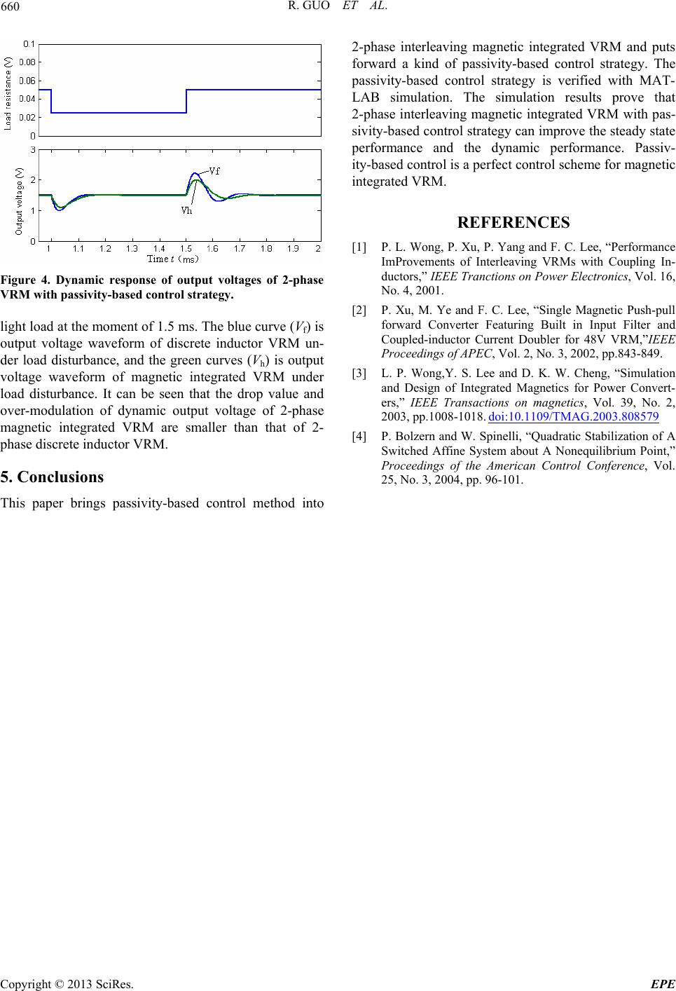 R. GUO ET AL. 660 Figure 4. Dynamic response of output voltages of 2-phase VRM with passivity-based control strategy. light load at the moment of 1.5 ms. The blue curve (Vf) is output voltage waveform of discrete inductor VRM un- der load disturbance, and the green curves (Vh) is output voltage waveform of magnetic integrated VRM under load disturbance. It can be seen that the drop value and over-modulation of dynamic output voltage of 2-phase magnetic integrated VRM are smaller than that of 2- phase discrete inductor VRM. 5. Conclusions This paper brings passivity-based control method into 2-phase interleaving magnetic integrated VRM and puts forward a kind of passivity-based control strategy. The passivity-based control strategy is verified with MAT- LAB simulation. The simulation results prove that 2-phase interleaving magnetic integrated VRM with pas- sivity-based control strategy can improve the steady state performance and the dynamic performance. Passiv- ity-based control is a perfect control scheme for magnetic integrated VRM. REFERENCES [1] P. L. Wong, P. Xu, P. Yang and F. C. Lee, “Performance ImProvements of Interleaving VRMs with Coupling In- ductors,” IEEE Tranctions on Power Electronics, Vol. 16, No. 4, 2001. [2] P. Xu, M. Ye and F. C. Lee, “Single Magnetic Push-pull forward Converter Featuring Built in Input Filter and Coupled-inductor Current Doubler for 48V VRM,”IEEE Proceedings of APEC, Vol. 2, No. 3, 2002, pp.843-849. [3] L. P. Wong,Y. S. Lee and D. K. W. Cheng, “Simulation and Design of Integrated Magnetics for Power Convert- ers,” IEEE Transactions on magnetics, Vol. 39, No. 2, 2003, pp.1008-1018. doi:10.1109/TMAG.2003.808579 [4] P. Bolzern and W. Spinelli, “Quadratic Stabilization of A Switched Affine System about A Nonequilibrium Point,” Proceedings of the American Control Conference, Vol. 25, No. 3, 2004, pp. 96-101. Copyright © 2013 SciRes. EPE |