

Paper Menu >>
Journal Menu >>
 Modern Research in Catalysis, 2013, 2, 164-171 http://dx.doi.org/10.4236/mrc.2013.24022 Published Online October 2013 (http://www.scirp.org/journal/mrc) Experimental and Theoretical Properties of MoS2+x Nanoplatelets D. H. Galvan1,2, A. Posada Amarillas3, N. Elizondo2, M. José-Yacamán4 1On Sabbatical from Centro de Nanociencias y Nanotecnología, Universidad Nacional Autónoma de México, Ensenada, México 2Department of Chemical Engineering and International Center for Nanotechnology & Advanced Materials, University of Texas at Austin, Austin, USA 3Departamento de Investigación en Física, Universidad de Sonora, Hermosillo, México 4Department of Physics and Astronomy, University of Texas at San Antonio, One UTSA Circle, San Antonio, USA Email: [email protected] Received April 6, 2013; revised July 5, 2013; accepted August 18, 2013 Copyright © 2013 D. H. Galvan et al. This is an open access article distributed under the Creative Commons Attribution License, which permits unrestricted use, distribution, and reproduction in any medium, provided the original work is properly cited. ABSTRACT The synthesis and the catalysis in the HDS of DBT reaction of nanostructured self-supported catalyst containing MoS2+x nanoplatelets have been investigated. Enhancement of higher activity observed in sulfide catalyst sample (d) with re- spect to the ex situ and in situ references is more closely related to the morphology change of particles (nanoplatelets). In this work, we suggest that certain structures present in model catalysts maybe related to low dimensional structures and present a theoretical study of two MoS2 clusters (one made of 34 atoms/cluster and the second one made of 41 at- oms/cluster), to these clusters seven sulfur atoms were randomly located at the surface of the sulfur layer, in order to simulate certain structures resembling arrow shaped nanoplatelets that were found in a High Resolution TEM analysis performed in some MoS2 samples. Additionally, one of the goals is to enquire about the electronic properties presented in such structures when the clusters terminated as Mo- or S-edge and if it could be correlated to the catalyst behavior of these compounds. To the 34 atoms/cluster Mo-edge yielded metallic behavior while the second cluster the 41 atoms/ cluster S-edge yielded a semiconductor behavior with a forbidden energy gap Eg of the order of 3.6 eV between the Valence and Conductions bands respectively. Moreover, to the same clusters enunciated formerly, when the sulfur at- oms were located at the surface of the S-layer, for the first cluster (34 atoms/cluster) yielded a more metallic behavior, while the second one (41 atoms/cluster) yielded an isolator behavior. Our results agree with the experimental and theo- retical results presented by several groups in different laboratories arriving to the conclusion that the S-Mo-S Mo-edge arrow heads structures could be responsible to the enhancement of the catalytic activity on the MoS2 studied samples. Keywords: Hydrodesulfurization; Tight-Binding; Catalyst; Tem; Clusters 1. Introduction The most commonly used industrial hydro treating cata- lysts for sulfur removal from heavy oils are based on cobalt or nickel promoted MoS2 [1]. Atom-resolved scanning tunneling microscopy (STM) studies of catalyst model systems have recently given the first direct insight into the atomic-scale structure of mo- del MoS2 nanoclusters and the promoted CoMoS struc- tures [2,3]. These model systems consisted of a few na- nometer wide, gold-supported MoS2 and CoMoS nano- clusters, and with the STM, it was possible to characterize their geometrical and electronic structure in great detail. On this basis, new important insight was obtained on the nanocluster morphology, on the atomic-scale structure of the catalytically important edges, and on the formation of sulfur vacancies. It was also shown that the nanocluster morphology and exact edge structures were sensitive to reaction conditions [4-8]. Those catalysts consist of small MoS2+x particles of fi- nite size supported on alumina. A more deep analysis of these wires shows a remarkable structure which resembles to the theoretical models used by several groups [1-11]. Figures 1(a) and (b) show how a typical catalyst can be formed by these nanoplatelets of MoS2 that also show an enhanced selectivity toward hydrogenation [12]. Two types of structures can be seen: triangular platelets and cone shaped platelets. These structures contain metallic edge sites (brims). C opyright © 2013 SciRes. MRC 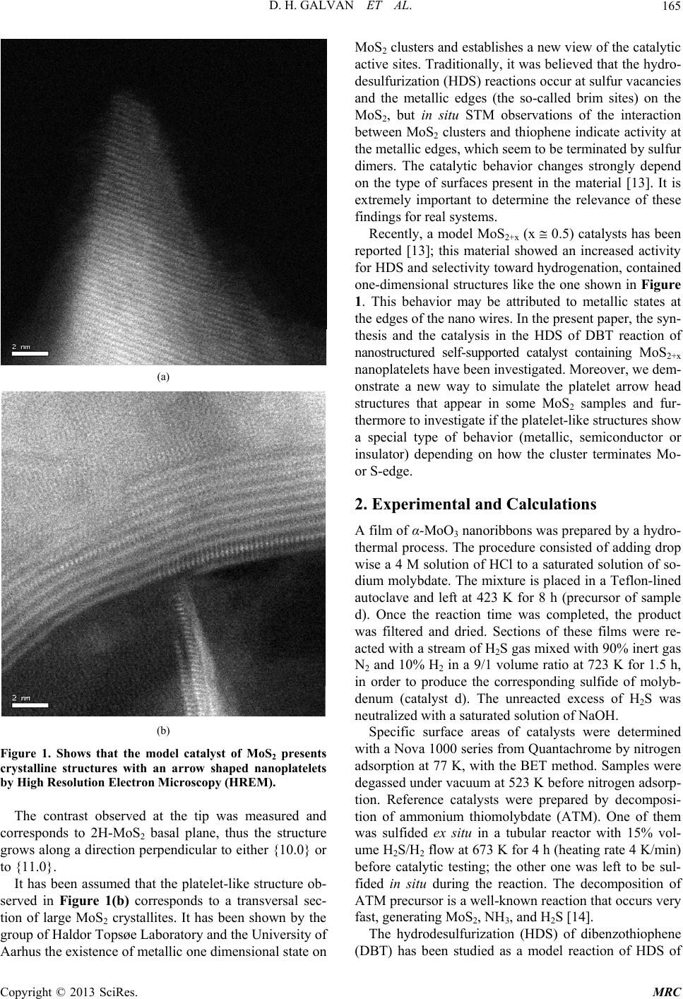 D. H. GALVAN ET AL. 165 (a) (b) Figure 1. Shows that the model catalyst of MoS2 presents he contrast observed at the tip was measured and co n assumed that the platelet-like structure ob- se 2+x (x 0.5) catalysts has been re 2. Experimental and Calculations d by a hydro- ermined w nzothiophene (D crystalline structures with an arrow shaped nanoplatelets by High Resolution Electron Microscopy (HREM). T rresponds to 2H-MoS2 basal plane, thus the structure grows along a direction perpendicular to either {10.0} or to {11.0}. It has bee rved in Figure 1(b) corresponds to a transversal sec- tion of large MoS2 crystallites. It has been shown by the group of Haldor Topsøe Laboratory and the University of Aarhus the existence of metallic one dimensional state on MoS2 clusters and establishes a new view of the catalytic active sites. Traditionally, it was believed that the hydro- desulfurization (HDS) reactions occur at sulfur vacancies and the metallic edges (the so-called brim sites) on the MoS2, but in situ STM observations of the interaction between MoS2 clusters and thiophene indicate activity at the metallic edges, which seem to be terminated by sulfur dimers. The catalytic behavior changes strongly depend on the type of surfaces present in the material [13]. It is extremely important to determine the relevance of these findings for real systems. Recently, a model MoS ported [13]; this material showed an increased activity for HDS and selectivity toward hydrogenation, contained one-dimensional structures like the one shown in Figure 1. This behavior may be attributed to metallic states at the edges of the nano wires. In the present paper, the syn- thesis and the catalysis in the HDS of DBT reaction of nanostructured self-supported catalyst containing MoS2+x nanoplatelets have been investigated. Moreover, we dem- onstrate a new way to simulate the platelet arrow head structures that appear in some MoS2 samples and fur- thermore to investigate if the platelet-like structures show a special type of behavior (metallic, semiconductor or insulator) depending on how the cluster terminates Mo- or S-edge. A film of α-MoO3 nanoribbons was prepare thermal process. The procedure consisted of adding drop wise a 4 M solution of HCl to a saturated solution of so- dium molybdate. The mixture is placed in a Teflon-lined autoclave and left at 423 K for 8 h (precursor of sample d). Once the reaction time was completed, the product was filtered and dried. Sections of these films were re- acted with a stream of H2S gas mixed with 90% inert gas N2 and 10% H2 in a 9/1 volume ratio at 723 K for 1.5 h, in order to produce the corresponding sulfide of molyb- denum (catalyst d). The unreacted excess of H2S was neutralized with a saturated solution of NaOH. Specific surface areas of catalysts were det ith a Nova 1000 series from Quantachrome by nitrogen adsorption at 77 K, with the BET method. Samples were degassed under vacuum at 523 K before nitrogen adsorp- tion. Reference catalysts were prepared by decomposi- tion of ammonium thiomolybdate (ATM). One of them was sulfided ex situ in a tubular reactor with 15% vol- ume H2S/H2 flow at 673 K for 4 h (heating rate 4 K/min) before catalytic testing; the other one was left to be sul- fided in situ during the reaction. The decomposition of ATM precursor is a well-known reaction that occurs very fast, generating MoS2, NH3, and H2S [14]. The hydrodesulfurization (HDS) of dibe BT) has been studied as a model reaction of HDS of Copyright © 2013 SciRes. MRC 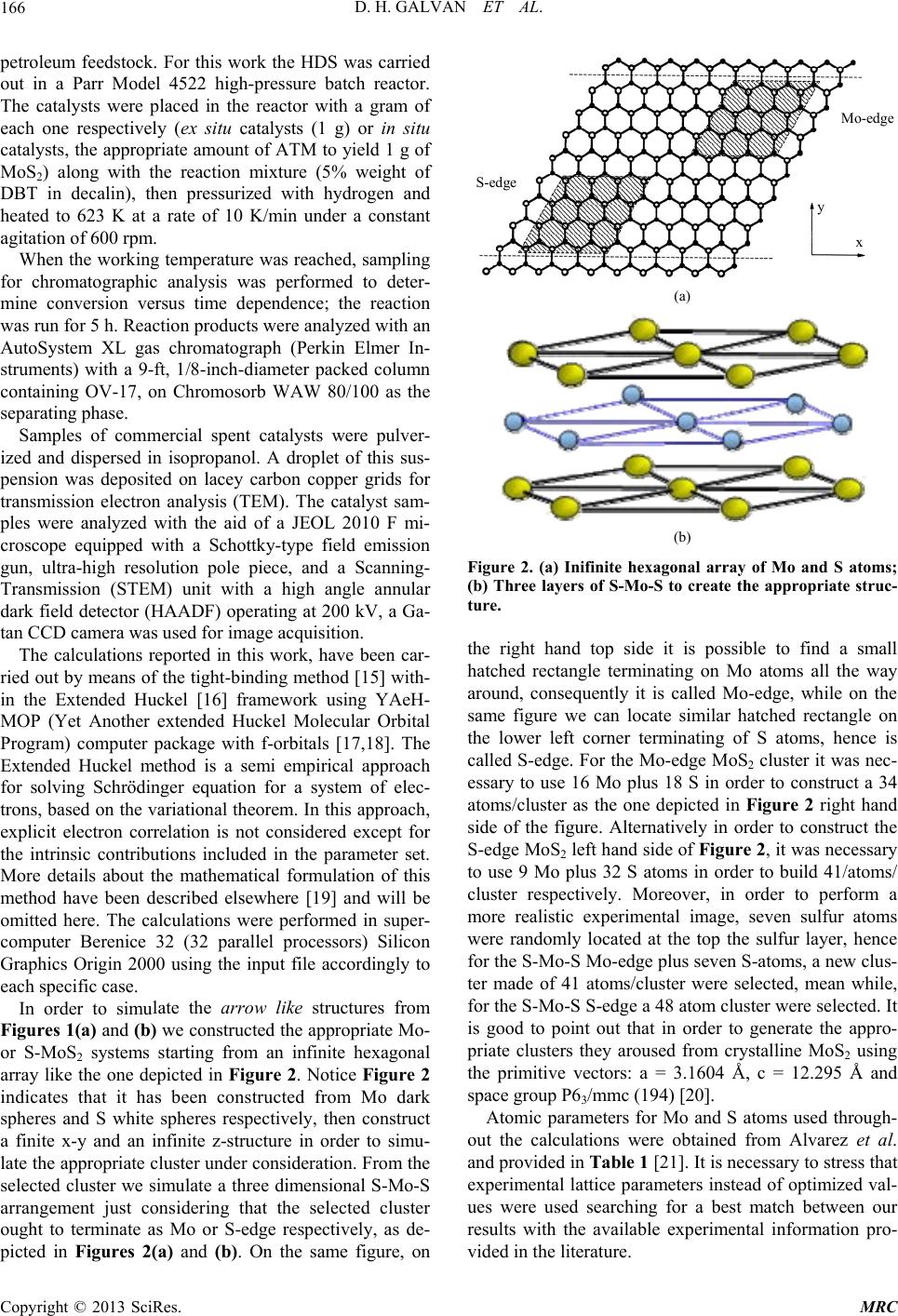 D. H. GALVAN ET AL. 166 petroleum feedstock. For this work the HDS was carried out in a Parr Model 4522 high-pressure batch reactor. The catalysts were placed in the reactor with a gram of each one respectively (ex situ catalysts (1 g) or in situ catalysts, the appropriate amount of ATM to yield 1 g of MoS2) along with the reaction mixture (5% weight of DBT in decalin), then pressurized with hydrogen and heated to 623 K at a rate of 10 K/min under a constant agitation of 600 rpm. When the working temperature was reached, sampling fo mercial spent catalysts were pulver- iz car- rie late the arrow like structures from Fi r chromatographic analysis was performed to deter- mine conversion versus time dependence; the reaction was run for 5 h. Reaction products were analyzed with an AutoSystem XL gas chromatograph (Perkin Elmer In- struments) with a 9-ft, 1/8-inch-diameter packed column containing OV-17, on Chromosorb WAW 80/100 as the separating phase. Samples of com ed and dispersed in isopropanol. A droplet of this sus- pension was deposited on lacey carbon copper grids for transmission electron analysis (TEM). The catalyst sam- ples were analyzed with the aid of a JEOL 2010 F mi- croscope equipped with a Schottky-type field emission gun, ultra-high resolution pole piece, and a Scanning- Transmission (STEM) unit with a high angle annular dark field detector (HAADF) operating at 200 kV, a Ga- tan CCD camera was used for image acquisition. The calculations reported in this work, have been d out by means of the tight-binding method [15] with- in the Extended Huckel [16] framework using YAeH- MOP (Yet Another extended Huckel Molecular Orbital Program) computer package with f-orbitals [17,18]. The Extended Huckel method is a semi empirical approach for solving Schrödinger equation for a system of elec- trons, based on the variational theorem. In this approach, explicit electron correlation is not considered except for the intrinsic contributions included in the parameter set. More details about the mathematical formulation of this method have been described elsewhere [19] and will be omitted here. The calculations were performed in super- computer Berenice 32 (32 parallel processors) Silicon Graphics Origin 2000 using the input file accordingly to each specific case. In order to simu gures 1(a) and (b) we constructed the appropriate Mo- or S-MoS2 systems starting from an infinite hexagonal array like the one depicted in Figure 2. Notice Figure 2 indicates that it has been constructed from Mo dark spheres and S white spheres respectively, then construct a finite x-y and an infinite z-structure in order to simu- late the appropriate cluster under consideration. From the selected cluster we simulate a three dimensional S-Mo-S arrangement just considering that the selected cluster ought to terminate as Mo or S-edge respectively, as de- picted in Figures 2(a) and (b). On the same figure, on y x S-edge Mo-edge (a) (b) Figure 2. (a) Inifinite hexagonal array of Mo and S atoms; e right hand top side it is possible to find a small S atoms used through- ou (b) Three layers of S-Mo-S to create the appropriate struc- ture. th hatched rectangle terminating on Mo atoms all the way around, consequently it is called Mo-edge, while on the same figure we can locate similar hatched rectangle on the lower left corner terminating of S atoms, hence is called S-edge. For the Mo-edge MoS2 cluster it was nec- essary to use 16 Mo plus 18 S in order to construct a 34 atoms/cluster as the one depicted in Figure 2 right hand side of the figure. Alternatively in order to construct the S-edge MoS2 left hand side of Figure 2, it was necessary to use 9 Mo plus 32 S atoms in order to build 41/atoms/ cluster respectively. Moreover, in order to perform a more realistic experimental image, seven sulfur atoms were randomly located at the top the sulfur layer, hence for the S-Mo-S Mo-edge plus seven S-atoms, a new clus- ter made of 41 atoms/cluster were selected, mean while, for the S-Mo-S S-edge a 48 atom cluster were selected. It is good to point out that in order to generate the appro- priate clusters they aroused from crystalline MoS2 using the primitive vectors: a = 3.1604 Å, c = 12.295 Å and space group P63/mmc (194) [20]. Atomic parameters for Mo and t the calculations were obtained from Alvarez et al. and provided in Table 1 [21]. It is necessary to stress that experimental lattice parameters instead of optimized val- ues were used searching for a best match between our results with the available experimental information pro- vided in the literature. Copyright © 2013 SciRes. MRC 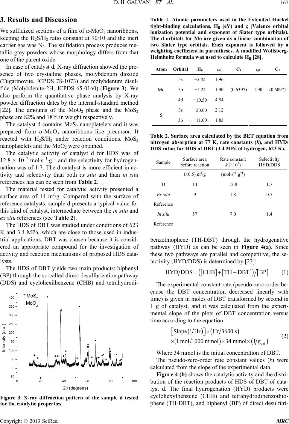 D. H. GALVAN ET AL. 167 3. Results and Discussion f α-MoO3 nanoribbons, t at 90/10 and the inert e phases, molybdenum dioxide (T ursor. It re r hydrogen- na e surface of re those used in indus- tri rough the so-called direct desulfurization pathway (D We sulfidized sections of a film o keeping the HS/H ratio constan 2 2 carrier gas was N2. The sulfidation process produces me- tallic grey powders whose morphology differs from that one of the parent oxide. In case of catalyst d, X-ray diffraction showed the pre- sence of two crystallin ugarinovite, JCPDS 78-1073) and molybdenum disul- fide (Molybdenite-2H, JCPDS 65-0160) (Figure 3). We also perform the quantitative phase analysis by X-ray powder diffraction dates by the internal-standard method [22]. The amounts of the MoO2 phase and the MoS2 phase are 82% and 18% in weight respectively. The catalyst d contains MoS2 nanoplatelets and it was prepared from α-MoO3 nanoribbons like prec acted with H2S/H2 under reaction conditions. MoS2 nanoplatelets and the MoO2 were obtained. The catalytic activity of catalyst d for HDS was of 12.8 × 10⁻⁷ mol·s−1·g−1 and the selectivity fo tion was of 1.7. The d catalyst is more efficient in ac- tivity and selectivity than both ex situ and than in situ references has can be seen from Table 2. The material tested for catalytic activity presented a surface area of 14 m2/g. Compared with th ference catalysts, sample d presents a typical value for this kind of catalyst, intermediate between the in situ and ex situ references (see Table 2). The HDS of DBT was studied under conditions of 623 K and 3.4 MPa, which are close to al applications. DBT was chosen because it is consid- ered an appropriate compound for the investigation of activity and reaction mechanisms of proposed HDS cata- lysts. The HDS of DBT yields two main products: biphenyl (BP) th DS) and cyclohexilbenzene (CHB) and tetrahydrodi- 400 020406080 100 -50 0 50 100 150 200 250 300 350 .* . . . * . . .* . . * * . * * . ** * . Intensity (a.u.) 2 (degrees) * MoS2. . MoO2 * Figure 3. X-ray diffraction pattern of the sample d tested for the catalytic properties. (eV) and (Valence orbital C2 Table 1. Atomic parameters used in the Extended Huckel tight-binding calculations, Hii ionization potential and exponent of Slater type orbitals). The d-orbitals for Mo are given as a linear combination of two Slater type orbitals. Each exponent is followed by a weighting coefficient in parentheses. A modified Wolfsberg- Helmholtz formula was used to calculate Hij [28]. Atom OrbitalHii i1 C1 i2 5s −8.34 1.96 5p −5.241.90 Mo (0.6397) 1.90 (0.6097) S 4d −10.50 4.54 3s −20.00 2.12 3p −11.00 1.83 Table 2. Sue acuby the BET equation from itrogen absorption at 77 K, rate constants (k), and HYD/ rfacrea callated n DDS ratios for HDS of DBT (3.4 MPa of hydrogen, 623 K). Sample Surface area before reaction Rate constant k (×107) Selectivity HYD/DDS (±0.5) m/g 2(m −1−1) ol·s ·g D 14 12.8 1. Ex situ Reference 57 7. 1. Reference 7 9 1.8 0.5 In situ 0 4 phene (TH-DBT) throh the hydrogenative b p enzothio ug athway (HYD) as can be seen in Figure 4(a). Since these two pathways are parallel and competitive, the se- lectivity (HYD/DDS) is determined by [23]: HYD DDSCHBTHDBTBP (1) The experimental constant rate (pseudo-zero-o cause t rder be- he DBT concentration decreased linearly with time) is given in moles of DBT transformed by second in 1 g of catalyst, and it was calculated from the experi- mental slope of the plots of DBT concentration versus time according to the equation: cat 00 s 1mol1000 mmol34 mmol1 g (2) Where 34 mmol is the initial concentration of DBT. ca Slope1 HrHr36 The pseudo-zero-order rate constant values (k) were lculated from the slope of the experimental data. Figure 4 (b) shows the catalytic activity and the distri- bution of the reaction products of HDS of DBT of cata- lyst d. The final hydrogenation (HYD) products were cyclohexylbenzene (CHB) and tetrahydrodibenzothio- phene (TH-DBT), and biphenyl (BP) of direct desulfuri- Copyright © 2013 SciRes. MRC 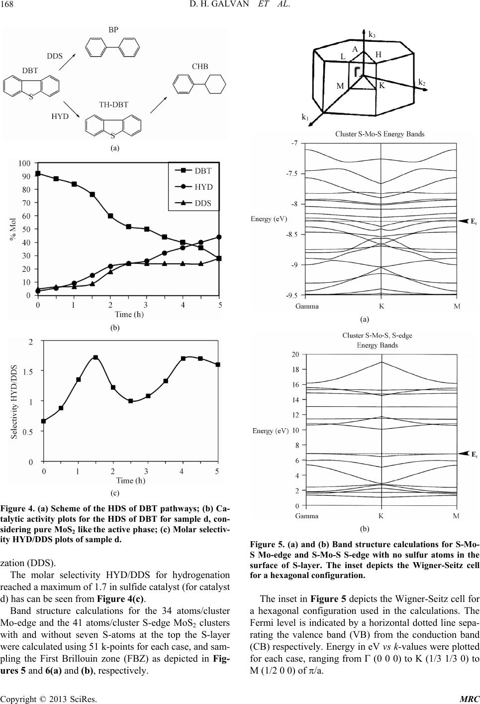 D. H. GALVAN ET AL. 168 (a) (b) (c) Figure 4. (a) Scheme of the HDS of DBT pathways; (b) Ca- talytic activity plots for the sample d, con- The molar selectivity HYD/DDS for hydrogenation um of 1.7 in sulfide catalyst (for catalyst d) MoS clusters w HDS of DBT for sidering pure MoS2 like the active phase; (c) Molar selectiv- ity HYD/DDS plots of sample d. zation (DDS). reached a maxim has can be seen from Figure 4(c). Band structure calculations for the 34 atoms/cluster Mo-edge and the 41 atoms/cluster S-edge2 ith and without seven S-atoms at the top the S-layer were calculated using 51 k-points for each case, and sam- pling the First Brillouin zone (FBZ) as depicted in Fig- ures 5 and 6(a) and (b), respectively. k 3 A H L M k 1 K k 2 (a) (b) Figure 5. (a) and (b) Band structure calculations for S-Mo- S Mo-edge and S-Mo-S S-edith no sulfur atoms in the ts the Wigner-Seitz cell for a hexagonal configuration used in the calculations. The Fe M (1/2 0 0) of /a. ge w surface of S-layer. The inset depicts the Wigner-Seitz cell for a hexagonal configuration. The inset in Figure 5 depic rmi level is indicated by a horizontal dotted line sepa- rating the valence band (VB) from the conduction band (CB) respectively. Energy in eV vs k-values were plotted for each case, ranging from (0 0 0) to K (1/3 1/3 0) to Copyright © 2013 SciRes. MRC 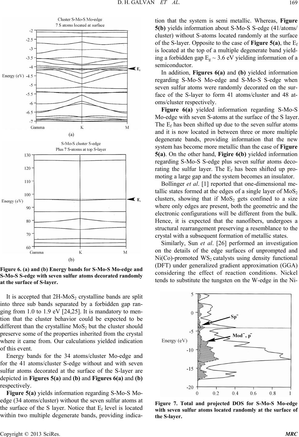 D. H. GALVAN ET AL. 169 (a) (b) Figure 6. (a) and (b) Energy bands for S-Mo-S Mo-edge and S-Mo-S S-edge with seve n sulfur atoms decorated randoml at the surface of S-layer. parated by a forbidden gap ran- gi from 1.0 to 1.9 eV [24,25]. It is mandatory to men- tio ecorated at the surface of the S-layer are de the S layer. Notice that Ef level is located w s were randomly decorated on the sur- fa p due to the seven sulfur atoms an w (D y It is accepted that 2H-MoS2 crystalline bands are split into three sub bands se ng n that the cluster behavior could be expected to be different than the crystalline MoS2 but the cluster should preserve some of the properties inherited from the crystal where it came from. Our calculations yielded indication of this event. Energy bands for the 34 atoms/cluster Mo-edge and for the 41 atoms/cluster S-edge without and with seven sulfur atoms d picted in Figures 5(a) and (b) and Figures 6(a) and (b) respectively. Figure 5(a) yields information regarding S-Mo-S Mo- edge (34 atoms/cluster) without the seven sulfur atoms at the surface of ithin two multiple degenerate bands, providing indica- tion that the system is semi metallic. Whereas, Figure 5(b) yields information about S-Mo-S S-edge (41/atoms/ cluster) without S-atoms located randomly at the surface of the S-layer. Opposite to the case of Figure 5(a), the Ef is located at the top of a multiple degenerate band yield- ing a forbidden gap Eg ~ 3.6 eV yielding information of a semiconductor. In addition, Figures 6(a) and (b) yielded information regarding S-Mo-S Mo-edge and S-Mo-S S-edge when seven sulfur atom ce of the S-layer to form 41 atoms/cluster and 48 at- oms/cluster respectively. Figure 6(a) yielded information regarding S-Mo-S Mo-edge with seven S-atoms at the surface of the S layer. The Ef has been shifted u d it is now located in between three or more multiple degenerate bands, providing information that the new system has become more metallic than the case of Figure 5(a). On the other hand, Figire 6(b) yielded information regarding S-Mo-S S-edge plus seven sulfur atoms deco- rating the sulfur layer. The Ef has been shifted up pro- moting a large gap and the system becomes an insulator. Bollinger et al. [1] reported that one-dimensional me- tallic states formed at the edges of a single layer of MoS2 clusters, showing that if MoS2 gets confined to a size here only edges are present, both the geometric and the electronic configurations will be different from the bulk. Hence, it is expected that the nanofibers, undergoes a structural rearrangement preserving a resemblance to the crystal with a subsequent formation of metallic states. Similarly, Sun et al. [26] performed an investigation on the details of the edge surfaces of unprompted and Ni(Co)-promoted WS2 catalysts using density functional FT) under generalized gradient approximation (GGA) considering the effect of reaction conditions. Nickel tends to substitute the tungsten on the W-edge in the Ni- Figure 7. Total and projected DOS for S-Mo-S Mo-edge with seven sulfur atoms located randomly at the surface of the S-layer. Copyright © 2013 SciRes. MRC 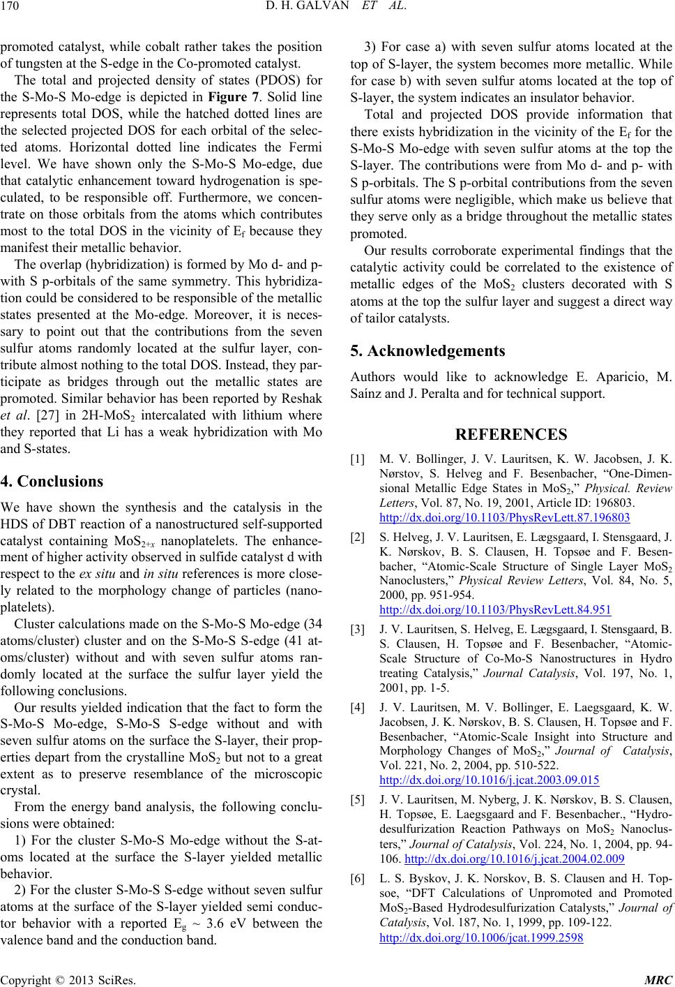 D. H. GALVAN ET AL. 170 promoted catalyst, while cobalt rather takes the position of tungsten at the S-edge in the Co-promoted catalyst. The total and projected density of states (PDOS) for the S-Mo-S Mo-edge is depicted in Figure 7. Solid line represents total DOS, while the hatched dotted lines are the selected projected DOS for each orbital of the selec- ted atoms. Horizontal dotted line indicates the Fermi level. We have shown only the S-Mo-S Mo-edge, due that catalytic enhancement toward hydrogenation is spe- culated, to be responsible off. Furthermore, we concen- trate on those orbitals from the atoms which contributes most to the total DOS in the vicinity of Ef because they manifest their metallic behavior. The overlap (hybridization) is formed by Mo d- and p- with S p-orbitals of the same symmetry. This hybridiza- tion could be considered to be responsible of the metallic states presented at the Mo-edge. Moreover, it is neces- sary to point out that the contributions from the seven sulfur atoms randomly located at the sulfur layer, con- tribute almost nothing to the total DOS. Instead, they par- ticipate as bridges through out the metallic states are promoted. Similar behavior has been reported by Reshak et al. [27] in 2H-MoS2 intercalated with lithium where they reported that Li has a weak hybridization with Mo and S-states. 4. Conclusions We have shown the synthesis and the catalysis in the on of a nanostructured self-supported va ated at the top of S- p the S- ges of the MoS clusters decorated with S at e to acknowledge E. Aparicio, M. chnical support. [1] M. V. Bollinger, J. V. Lauritsen, K. W. Jacobsen, J. K. Nørstov, S. Hher, “One-Dimen- sional MetallicPhysical. Review HDS of DBT reacti Let catalyst containing MoS2+x nanoplatelets. The enhance- ment of higher activity observed in sulfide catalyst d with respect to the ex situ and in situ references is more close- ly related to the morphology change of particles (nano- platelets). Cluster calculations made on the S-Mo-S Mo-edge (34 atoms/cluster) cluster and on the S-Mo-S S-edge (41 at- oms/cluster) without and with seven sulfur atoms ran- domly located at the surface the sulfur layer yield the following conclusions. Our results yielded indication that the fact to form the S-Mo-S Mo-edge, S-Mo-S S-edge without and with seven sulfur atoms on the surface the S-layer, their prop- erties depart from the crystalline MoS2 but not to a great extent as to preserve resemblance of the microscopic crystal. From the energy band analysis, the following conclu- sions were obtained: 1) For the cluster S-Mo-S Mo-edge without the S-at- oms located at the surface the S-layer yielded metallic behavior. 2) For the cluster S-Mo-S S-edge without seven sulfur atoms at the surface of the S-layer yielded semi conduc- tor behavior with a reported Eg ~ 3.6 eV between the lence band and the conduction band. 3) For case a) with seven sulfur atoms located at the top of S-layer, the system becomes more metallic. While for case b) with seven sulfur atoms loc layer, the system indicates an insulator behavior. Total and projected DOS provide information that there exists hybridization in the vicinity of the Ef for the S-Mo-S Mo-edge with seven sulfur atoms at the to layer. The contributions were from Mo d- and p- with S p-orbitals. The S p-orbital contributions from the seven sulfur atoms were negligible, which make us believe that they serve only as a bridge throughout the metallic states promoted. Our results corroborate experimental findings that the catalytic activity could be correlated to the existence of metallic ed2 oms at the top the sulfur layer and suggest a direct way of tailor catalysts. 5. Acknowledgements Authors would lik Saínz and J. Peralta and for te REFERENCES elveg and F. Besenbac Edge States in MoS2,” ters, Vol. 87, No. 19, 2001, Article ID: 196803. http://dx.doi.org/10.1103/PhysRevLett.87.196803 [2] S. Helveg, J. V. Lauritsen, E. Lægsgaard, I. Stensgaard, J. K. Nørskov, B. S. Clausen, H. Topsøe and F. B bacher, “Atomic-Scale Structure of Single Layer esen- MoS2 Nanoclusters,” Physical Review Letters, Vol. 84, No. 5, 2000, pp. 951-954. http://dx.doi.org/10.1103/PhysRevLett.84.951 [3] J. V. Lauritsen, S. Helveg, E. Lægsgaard, I. Stensgaard, B. S. Clausen, H. Tops Scale Structure of Co-Mo-S Nanostructures øe and F. Besenbacher, “Atomic- in Hydro tomic-Scale Insight into Structure and treating Catalysis,” Journal Catalysis, Vol. 197, No. 1, 2001, pp. 1-5. [4] J. V. Lauritsen, M. V. Bollinger, E. Laegsgaard, K. W. Jacobsen, J. K. Nørskov, B. S. Clausen, H. Topsøe and F. Besenbacher, “A Morphology Changes of MoS2,” Journal of Catalysis, Vol. 221, No. 2, 2004, pp. 510-522. http://dx.doi.org/10.1016/j.jcat.2003.09.015 [5] J. V. Lauritsen, M. Nyberg, J. K. Nørskov, B. S. Clausen, H. Topsøe, E. Laegsgaard and F. Bes desulfurization Reaction Pathways on MoS enbacher., “Hydro- 2 Nanoclus- ters,” Journal of Catalysis, Vol. 224, No. 1, 2004, pp. 94- 106. http://dx.doi.org/10.1016/j.jcat.2004.02.009 [6] L. S. Byskov, J. K. Norskov, B. S. Clausen and H. Top- soe, “DFT Calculations of Unpromoted and Promoted MoS2-Based Hydrodesulfurization Catalysts,” Journal of Catalysis, Vol. 187, No. 1, 1999, pp. 109-122. http://dx.doi.org/10.1006/jcat.1999.2598 Copyright © 2013 SciRes. MRC  D. H. GALVAN ET AL. Copyright © 2013 SciRes. MRC 171 2000, pp 3709813 [17] G. A. Landrum, “F Orbitals Are Included in the Calcula- n- . Galvan, “An Extended Hückel Calculation on [7] L. S. Byskov, J. K. Norskov, B. S. Clausen and H. Top- soe, “Edge Termination of MoS2 and CoMoS Catalyst Particles,” Catalysis Letters, Vol. 64, No. 2-4, 95-99. tions as Version 3.0x, Using W. V. Glassey’s Routine.” http://overlap.chem.Cornell.edu:8080/yaehmop.html [18] W. V. Glassey, G. A. Papoian, R. Hoffmann, “Total E . http://dx.doi.org/10.1023/A:101906 o. 1 [8] H. Schweiger, P. Raybaud, G. Kresse and H. Toulhoat, “Shape and Edge State Modification of MoS2 Catalytic Nanoparticles Induced by Working Copnditions: A The- oretical Study,” Journal of. Cataysis, Vol.. 207, N ergy Partitioning within a One-electron Formalism: A Hamiltonean Population Study of Surface-CO Interaction in the C(2x2)-CO/Ni(100) Chemisorption System,” Jour- nal of Chemical Physics, Vol. 111, No. 3, 1999, pp. 893- 910. [19] D. H , 2002, pp. 76-87. http://dx.doi.org/10.1006/jcat.2002.3508 [9] A. Carlsson, M. Brorson and H. Topse, “Morphology of WS2 Nanoclusters in WS2/C Hydrodesulfurization Cata- lysts Revealed by High-Angle Annular Dark-Field Trans- mission Electron Microscopy (HAADF-STEM) Imag- Cubic Boron Nitride and Diamond,” Journal of Materials Science Letters, Vol. 17, No. 10, 1998, pp. 805-810. http://dx.doi.org/10.1023/A:1006630320896 [20] P. D. Fleischauer, J. R. Lince, P. A. Bertrand, ing,” Journal of Catalysis, Vol. 227, No. 2, 2004, pp. 530-536. http://dx.doi.org/10.1016/j.jcat.2004.08.031 [10] M. Egorova and R. Prins, “Hydrodesulfurization of Di- benzothiophene and 4,6-Dymethyldibenzothiophene over Sulfided NiMo/γ-Al2O3, CoMo/γ-Al2O3 and Mo/γ-Al2O3 Catalysts,” Journal of Catalysis, Vol. 225, No. 2, 20 R. Baner, “Electronic Structure and Lubrication Properties of MoS2: A Qualitative Molecular Orbital Approach,” Langmuir, Vol. 5, No. 4, 1989, pp. 1009-1015. http://dx.doi.org/10.1021/la00088a022 [21] S. Alvarez, “Tables of Parameters for 04, Extended Huckel . Witehurst, T. Isoda and I. Mochida, “Present State pp. 417-427. http://dx.doi.org/10.1016/j.jcat.2004.05.002 [11] M. Egorova and R. Prins. “Competitive Hydrodesulfuri- zation of 4, 6 Dimethyldibenzothiophene, Hydrodinitro- genation of 2-Methylpyridine, and Hydrogenation of Naphtalene over Sulfided NiMo/γ-Al2O3,” Journal of Ca- Calculations,” Universitat de Barcelona, Barcelon, 1993. [22] E. Lifshin, “X-Ray Charactrization of Materials,” Wiley- VCH, Weinheim, Federal Republic of Germany, 1999, p. 74. [23] D. D talysis, Vol. 224, No. 2, 2004, pp. 278-287. http://dx.doi.org/10.1016/j.jcat.2004.03.005 [12] F. Dumeignil, K. Sato, M. Imamura, N. Matsubayashi, E. Payen and H. Shimada, “Characterization and Hydrode- sulfurization Activity of CoMo Catalyst S Sol-gel Preparated Al2O3,” Applied Catalysis of the Art and Future Challenges in the Hydrodesulfuri- zation of Polyaromatic Sulfur Compounds,” Advanced Catalysis, Vol. 42, No. 4, 1998, pp. 345-471. http://dx.doi.org/10.1016/S0360-0564(08)60631-8 [24] L. F. Mattheiss, “Band Structure of Transition- upported on A: General 2005, pp. 182-190. , Metal- itts and A. D. Yoffe, DFT Study of Cichalcogenides Layer Compounds,” Physical Review, Vol. 8, No. 8, 1973, pp. 3719-3740. [25] A. J. Grand, T. M. Griffiths, G. D. P Vo. 287, No. 1, 2005, pp. 135-145. [13] G. A. Camacho-Bragado, A. Olivas, S. Fuentes, D. H. Galvan and M. José-Yacamán, “Structure and Catalytic Properties of Nanostructured Molybdenum Sulfides,” Journal of Catalysis, Vol. 234, No. 1, “The Electrical Properties and the Magnitude of the Indi- rect Gap in the Semiconducting Transition Metal Dichal- cogenide Layer Crystals,” Journal of Physics C: Solid State Physics, Vol. 8, No. 1, 1975, p. L17. [26] M. Sun, A. E. Nelson and J. Adjaye, “A http://dx.doi.org/10.1016/j.jcat.2005.06.009 [14] T. P. Prasad, E. Diemann and A. Muller, “Thermal De- composition of (NH4)2MoO2S2, (NH4)2WO2S2 and (NH4)2WS4,” Journal of Inorganic and Nuclear Chemis- try, Vol. 35, No. 6, 1973, pp. 1895-1904. WS2, NiWS and CoWS Hydrotreating Catalysts,” Journal of Catalysis, Vol. 226, No. 1, 2004, pp. 41-53. http://dx.doi.org/10.1016/j.jcat.2004.04.023 [27] A. H. Reshak and S. Auluck, “Calculated Op http://dx.doi.org/10.1016/0022-1902(73)80124-1 [15] M.-H. Whangbo and R. Hoffmann, “The Band Structure of the Tetracyanoxilatinate Chain,” Journal of the Ameri- can Chemical Society, Vol. 100, No. 19, 6098. tical Proper- ctra and ties of 2H-MoS2 Intercalated with Lithium,” Physical Re- view, Vol. 68, No. 12, 2003, Article ID: 125101. [28] M. W. Wolfsberg and L. Helmholtz, “The Spe 1978, pp. 6093- http://dx.doi.org/10.1021/ja00487a020 Electronic Structure of the Tetrahedral Ions 4 MnO , 4 CrO and 4 ClO ,” Journal of chemical Physics, Vol, No. 5, 1952, pp. 837-843. . 20 [16] R. Hoffmann, “An Extended Hückel Theory of Hydro- carbons,” Journal of Chemical Physics, Vol. 39, No. 6, 1963, pp. 1397-1412. http://dx.doi.org/10.1063/1.1734456 |