

Paper Menu >>
Journal Menu >>
 Engineering, 2013, 5, 146-148 http://dx.doi.org/10.4236/eng.2013.510B031 Published Online October 2013 (http://www.scirp.org/journal/eng) Copyright © 2013 SciRes. ENG Multi-Layer Microbubbles by Microfluidics Hongbo Zhang*, Haosu Meng, Qian Sun, Jianpu Liu, W. J. Zhang Complex and Intelligent Research Centre, East China of Science and Technology, Shanghai, China Email: *[email protected] Received April 2013 ABSTRACT Multi-layer microbubble has great potential in enabling the corporation of medical imaging with tumor therapy such as drug and gene delivery of therapeutics or other functional materials in medical applications. Microfluidic technique has advanced over the last decade and showed great promise in replacing traditional microbubble generating method. In this paper, a multi-layer microbubble structure was produced with the aspect as potentially used for drug loaded microbub- ble contrast agents. Keywords: Microfluidic; Multi-Layer; Microbubbles; Medical Imaging 1. Introduction Microbubble as contrast agents in medical imaging is first invented in 1970s and it has greatly improved the quality of medical imaging over the decades. Recently, it has been found that microbubbles can be used to kill ma- lignant cells by releasing preloaded drugs and also by enhancing the drug transfer efficiency in ultrasound filed. It can also assist the drug targeting to the cells by the micro-jetting emitted by the microbubble when it col- lapses subjected to an intense ultrasound filed. This con- cept has encouraged researches to gener ate microbubbles with unique structures that meet the demand, but so far, there are still numerous obstacles remained. Microfluidic technique has been a promising tool to generate microbubbles owing to its number of merits, such as high monodispersity and controllable size distri- bution [1,2]. New attempts have been made to increase the production, for example, multi-array microchips [3] and sudden deepened configuration in the micro-channel [4]. The mechanism of microbubble generation by micro - fluidic is still not fully understood, but the most accepted theory is that in flow focusing (or co-flow) configuration, the microbubbles are generated by the instability of gas- liquid jets. Therefore, it can produce much smaller mi- crobubbles compared with the T-junction geometry [5]. The mechanism of the microbubble formation has been studied by the ultra high speed camera [6]. Their obser- vation suggests that the final moment of microbubble pinch-off in a cross focusing system is purely liquid iner- tia driven; however, surface tension is still important. The drug loaded microbubbles are mainly produced by attaching functional groups to the microbubble surface, which suffers the major defect that only selects group of drugs can be loaded [7]. Multilayer microbubbles might hold the key to succeeding drug loading function with high efficiency. The drug or gene can be encapsulated in the middle layer with a protection ou ter layer in the shell. Also due to the i mmer si on of the two layers, the outer layer can be liposome while the drug or gene aqueous liquid is in the middle. In this paper, a multi-channel mi- crofluidic device was constructed to generate multi-layer microbubbles. 2. Material The middle layer of the microbubble is between 80 (Amresco, Ltd.) and ionized water mixture (2% w/v), the outer layer is composed of liquid paraffin (Shanghai Lingfen g L t d.) and air is chosen as the gas phase. 3. Microbubble Generation The microfluidic configuration is shown in Figure 1. The depth of the channel is 25 μm, the width of the channel is 100 μm, the width of the joint is 20 μm and the length of the channel for each input is 7 mm. 4. Experiments The experimental setup is shown in Figure 2. Com- pressed air was regulated by a valve (Swagelok B-SS4- VI, USA) and a pressure sensor was used to monitor the pressure. Liquid phases were supplied by Syringe pumps (Stoelting 53100, USA). High speed camera (Microview MVC610DAM-GE110, USA) and microscopy (Sharp- scope SF-1, USA) was used to evaluate the microbubble generation process and s ize dist ribution of microbubbles. *Corresponding a uthor. 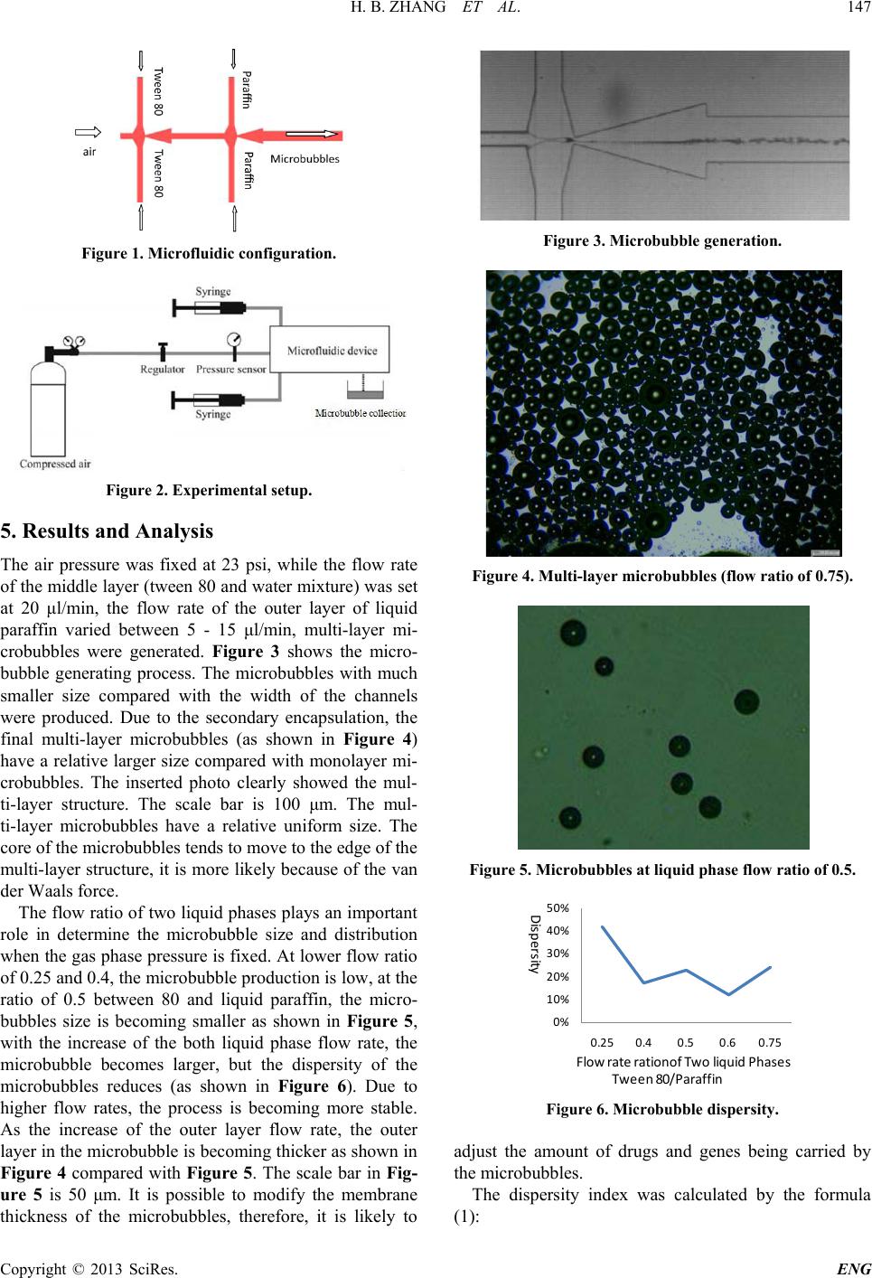 H. B. ZHANG ET AL. Copyright © 2013 SciRes. ENG 147 Figure 1. Microfluidic configuration. Figure 2. Experimental setup. 5. Results and Analysis The air pressure was fixed at 23 psi, while the flow rate of the middle layer (tween 80 and water mixture) was set at 20 μl/min, the flow rate of the outer layer of liquid paraffin varied between 5 - 15 μl/min, multi-layer mi- crobubbles were generated. Figure 3 shows the micro- bubble generating process. The microbubbles with much smaller size compared with the width of the channels were produced. Due to the secondary encapsulation, the final multi-layer microbubbles (as shown in Figure 4) have a relative larger size compared with monolayer mi- crobubbles. The inserted photo clearly showed the mul- ti-layer structure. The scale bar is 100 μm. The mul- ti-layer microbubbles have a relative uniform size. The core of the microbubbles tends to move to the edge of the mul ti-layer stru cture, it is more likely because of the van der Waals force. The flow ratio of two liquid phases plays an important role in determine the microbubble size and distribution when the gas phase pressure is fixed. At lower flow ratio of 0.25 and 0.4, the microbubble production is low, at the ratio of 0.5 between 80 and liquid paraffin, the micro- bubbles size is becoming smaller as shown in Figure 5, with the increase of the both liquid phase flow rate, the microbubble becomes larger, but the dispersity of the microbubbles reduces (as shown in Figure 6). Due to higher flow rates, the process is becoming more stable. As the increase of the outer layer flow rate, the outer layer in the microbubble is becoming thicker as shown in Figure 4 compared with Figure 5. The scale bar in Fig- ure 5 is 50 μm. It is possible to modify the membr an e thickness of the microbubbles, therefore, it is likely to Figure 3. Microbubble generation. Figure 4. Multi-layer microbubbl es (flow ratio of 0.75). Figure 5. Microbubbles at liquid phase flow ratio of 0.5. Figure 6. Microbubble dispersity. adjust the amount of drugs and genes being carried by the microbubbles. The dispersity index was calculated by the formula (1): 0% 10% 20% 30% 40% 50% 0.25 0.4 0.5 0.6 0.75 Dispersity Flow rate rationof Two liquid Phases Tween 80/Paraffin  H. B. ZHANG ET AL. Copyright © 2013 SciRes. ENG 148 dm CV D σ = (1) where d σ is the standard derivation, and m D is the mean diameter of microbubbles. Due to the higher surface tension of liquid paraffin to water of 72 dyn/cm, the multi-layer microbubbles cannot survive for more than 10 minute. The properties of the immiscible two liquid could play an important role in prolonging th e life time of microbubbles . 6. Conclusion Multi-layer microbubble structures have been produced by microfluidics. By adjusting the operating parameters, such as flow rate ratio, the microbubble size can be va- ried, so as the thickness of the microbubble membrane and it could offer a potential mean for gen eration of drug and gene loaded microbubble contrast agents to accom- plish the dual function as imaging and therapy of can- cers. 7. Acknowledgements This work is supported by the “One Thousand Talented Scheme” and the Fundamental Research Funds for the Central Universities in Chin a. REFERENCES [1] E. Talu, K. Hettiarachchi, R. L. Powell, A. P. Lee, P. A. Dayton, and M. L. Longo, “Maintaining Monodispersity in a Microbubble Population Formed by Flow-Focusing,” Langmuir, Vol. 24, 2008, pp. 1745-1749. http://dx.doi.org/10.1021/la703065v [2] K. Y. Song, W. J. Zhang and M. M. Gupta, “Size-Con- trollable Monodispersed Microsphere Generation by Liq- uid Chopper Utilizing PZT Actuator,” Journal of Micro- electromechanical Systems, Vol. 22, No. 1, 20 13, pp. 147- 151. [3] M. R. Kendall, D. Bardin, R. Shih, P. A. Dayton and A. P. Lee, “Scaled-Up Production Using Multi-Array Micro- fluidic Module for Medical Imaging and Drug Delivery,” Bubble Science, Engineering and Technology, Vol. 4, No. 1, 2012, pp. 12-20. [4] S. A. Peyman, R. H. Abou-Saleh, J. R. Mclaughlan, N. Ingram, B. R. G. Johnson, et al., “Expanding 3D Geome- try for Enhanced On-Chip Microbubble Production and Single Step Formation of Liposome Modified Microbub- bles,” Lab on Chip, Vol. 12, 2012, pp. 4544-4552. http://dx.doi.org/10.1039/c2lc40634a [5] E. Castro-Hernandez, W. van Hoeve, D. Lohse and J. M. Gordillo, “Microbubble Generation in a Co-Flow Device Operated in a New Regime,” Lab on Chip, Vol. 11, 2011, pp. 2023-2029. http://dx.doi.org/10.1039/c0lc00731e [6] W. Hoeve, B. Dollet, M. Versluis and D. Lohse, “Micro- bubble Formation and Pinch-Off Scaling Exponent in Flow Focusing Devices,” Physics of Fluids, Vol. 23, 2011, Article ID: 092001. http://dx.doi.org/10.1063/1.3631323 [7] I. Lentacker, B. G. Geest, R. E. broucke, et al., “Ultra- sound-Responsive Polymer Coated Microbubbles That Bind and Protect DNA,” Lamgmuir, Vol. 27, No. 17, 2006, pp. 341-334. |