

Paper Menu >>
Journal Menu >>
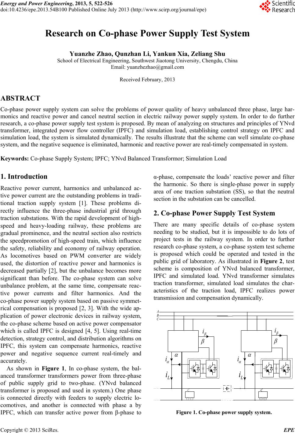 Energy and Power Engineering, 2013, 5, 522-526 doi:10.4236/epe.2013.54B100 Published Online July 2013 (http://www.scirp.org/journal/epe) Research on Co-phase Power Supply Test System Yuanzhe Zhao, Qunzhan Li, Yankun Xia, Zeliang Shu School of Electrical Engineering, Southwest Jiaotong University, Chengdu, China Email: [email protected] Received February, 2013 ABSTRACT Co-phase power supply system can solve the problems of power quality of heavy unbalanced three phase, large har- monics and reactive power and cancel neutral section in electric railway power supply system. In order to do further research, a co-phase power supply test system is proposed. By mean of analyzing on structures and principles of YNvd transformer, integrated power flow controller (IPFC) and simulation load, establishing control strategy on IPFC and simulation load, the system is simulated dynamically. The results illustrate that the scheme can well simulate co-phase system, and the negative sequence is eliminated, harmonic and reactive power are real-timely compensated in system. Keywords: Co-phase Supply System; IPFC; YNvd Balanced Transformor; Simulation Load 1. Introduction Reactive power current, harmonics and unbalanced ac- tive power current are the outstanding problems in tradi- tional traction supply system [1]. These problems di- rectly influence the three-phase industrial grid through traction substations. With the rapid development of high- speed and heavy-loading railway, these problems are gradual prominence, and the neutral section also restricts the speedpromotion of high-speed train, which influence the safety, reliability and economy of railway operation. As locomotives based on PWM converter are widely used, the distortion of reactive power and harmonics is decreased partially [2], but the unbalance becomes more significant than before. The co-phase system can solve unbalance problem, at the same time, compensate reac- tive power currents and filter harmonics. And the co-phase power supply system based on passive symmet- rical compensation is proposed [2, 3]. With the wide ap- plication of power electronic devices in railway system, the co-phase scheme based on active power compensator which is called IPFC is designed [4, 5]. Using real-time detection, strategy control, and distribution algorithms on IPFC, this system can compensate harmonics, reactive power and negative sequence current real-timely and accurately. As shown in Figure 1, In co-phase system, the bal- anced transformer transformers power from three-phase of public supply grid to two-phase. (YNvd balanced transformer is proposed and used in system.) One phase is connected directly with feeders to supply electric lo- comotives, and another is connected with phase a by IPFC, which can transfer active power from β-phase to α-phase, compensate the loads’ reactive power and filter the harmonic. So there is single-phase power in supply area of one traction substation (SS), so that the neutral section in the substation can be cancelled. 2. Co-phase Power Supply Test System There are many specific details of co-phase system needing to be studied, but it is impossible to do lots of project tests in the railway system. In order to further research co-phase system, a co-phase system test scheme is proposed which could be operated and tested in the public grid of laboratory. As illustrated in Figure 2, test scheme is composition of YNvd balanced transformer, IPFC and simulated load. YNvd transformer simulates traction transformer, simulated load simulates the char- acteristics of the traction load, IPFC realizes power transmission and compensation dynamically. i L i A B C i L i i i Figure 1. Co-phase pow er supply system. Copyright © 2013 SciRes. EPE 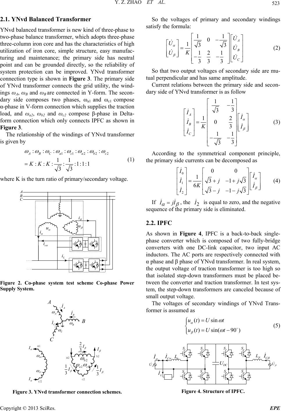 Y. Z. ZHAO ET AL. 523 2.1. YNvd Balanced Transformer YNvd balanced transformer is new kind of three-phase to two-phase balance transformer, which adopts three-phase three-column iron core and has the characteristics of high utilization of iron core, simple structure, easy manufac- turing and maintenance; the primary side has neutral point and can be grounded directly, so the reliability of system protection can be improved. YNvd transformer connection type is shown in Figure 3. The primary side of YNvd transformer connects the grid utility, the wind- ings ωA, ωB and ωB are connected in Y-form. The secon- dary side composes two phases, ωa1 and ωc1 compose α-phase in V-form connection which supplies the traction load, and ωa2, ωb2 and ωc2 compose β-phase in Delta- form connection which only connects IPFC as shown in Figure 3. The relationship of the windings of YNvd transformer is given by 11 2 2 ::: : ::: 11 ::: : :1:1:1 33 ABCa c abc KKK 2 (1) where K is the turn ratio of primary/secondary voltage. u i i c i L i A B C u Figure 2. Co-phase system test scheme Co-phase Power Supply System. A B C c1 A B C a1 C I B I A I 1a 1c 2a 2c 2b I I I 2 3I 1 3I a2 c2 b2 1 3I Figure 3. YNvd transformer connection schemes. So the voltages of primary and secondary windings satisfy the formula: 11 0 133 12 1 333 A B C U UU K UU (2) So that two output voltages of secondary side are mu- tual perpendicular and has same amplitude. Current relations between the primary side and secon- dary side of YNvd transformer is as follow 11 3 3 12 03 11 3 3 A B C I I IK I I (3) According to the symmetrical component principle, the primary side currents can be decomposed as 0 1 2 00 1313 6 313 I I Ijj K I Ijj (4) If I jI , the 2 I is equal to zero, and the negative sequence of the primary side is eliminated. 2.2. IPFC As shown in Figure 4, IPFC is a back-to-back single- phase converter which is composed of two fully-bridge converters with one DC-link capacitor, two input AC inductors. The AC ports are respectively connected with α phase and β phase of YNvd transformer. In real system, the output voltage of traction transformer is too high so that isolated step-down transformers must be placed be- tween the converter and traction transformer. In test sys- tem, the step-down transformers are canceled because of small output voltage. The voltages of secondary windings of YNvd Trans- former is assumed as () sin ( )sin(90 ) ut Ut ut Ut (5) 3 S 8 S 5 S 7 S 1 S 4 S 2 S 6 S L L U D C U C I C I I L I U Figure 4. Structure of IPFC. Copyright © 2013 SciRes. EPE 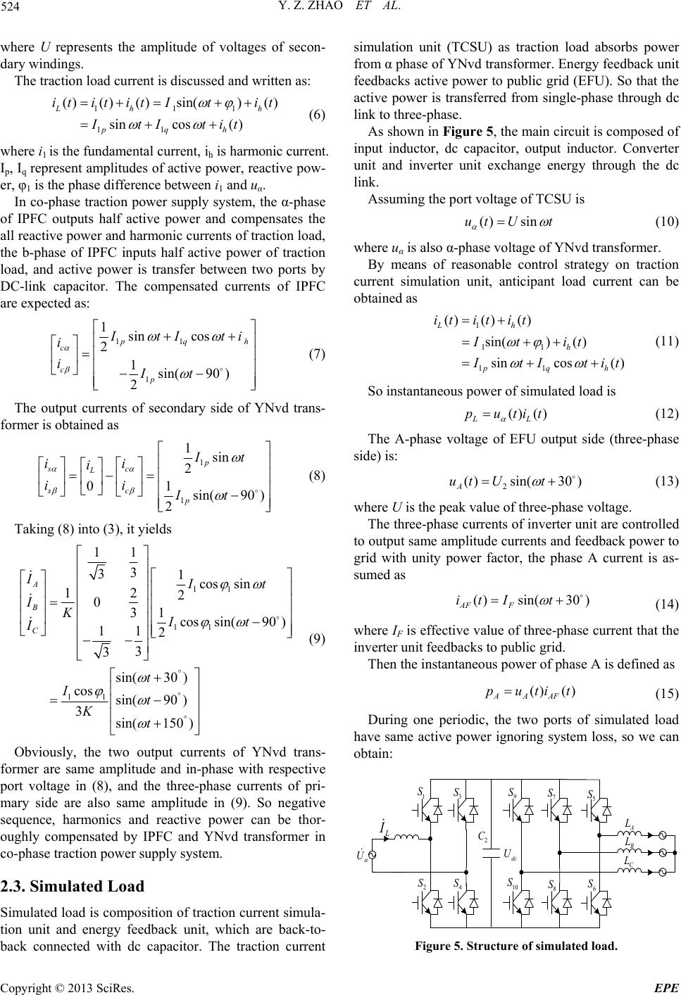 Y. Z. ZHAO ET AL. 524 where U represents the amplitude of voltages of secon- dary windings. The traction load current is discussed and written as: 111 11 () () ()sin() () sincos( ) Lh pqh itit itItit ItItit h (6) where i1 is the fundamental current, ih is harmonic current. Ip, Iq represent amplitudes of active power, reactive pow- er, φ1 is the phase difference between i1 and uα. In co-phase traction power supply system, the α-phase of IPFC outputs half active power and compensates the all reactive power and harmonic currents of traction load, the b-phase of IPFC inputs half active power of traction load, and active power is transfer between two ports by DC-link capacitor. The compensated currents of IPFC are expected as: 11 1 1sin cos 2 1sin(90) 2 p qh c c p I tI ti i iIt (7) The output currents of secondary side of YNvd trans- former is obtained as 1 1 1sin 2 1 0sin(90 ) 2 p sc L sc p It ii i ii It (8) Taking (8) into (3), it yields 11 11 11 11 3 31cos sin 12 2 01 3cossin(90 ) 11 2 3 3 sin(30 ) cos sin(90) 3sin(150 ) A B C IIt IKIt I t It Kt (9) Obviously, the two output currents of YNvd trans- former are same amplitude and in-phase with respective port voltage in (8), and the three-phase currents of pri- mary side are also same amplitude in (9). So negative sequence, harmonics and reactive power can be thor- oughly compensated by IPFC and YNvd transformer in co-phase traction power supply system. 2.3. Simulated Load Simulated load is composition of traction current simula- tion unit and energy feedback unit, which are back-to- back connected with dc capacitor. The traction current simulation unit (TCSU) as traction load absorbs power from α phase of YNvd transformer. Energy feedback unit feedbacks active power to public grid (EFU). So that the active power is transferred from single-phase through dc link to three-phase. As shown in Figure 5, the main circuit is composed of input inductor, dc capacitor, output inductor. Converter unit and inverter unit exchange energy through the dc link. Assuming the port voltage of TCSU is () sinut Ut (10) where uα is also α-phase voltage of YNvd transformer. By means of reasonable control strategy on traction current simulation unit, anticipant load current can be obtained as 1 11 11 () () () sin()() sincos( ) Lh h pq itit it It it h I tI tit (11) So instantaneous power of simulated load is () () LL putit (12) The A-phase voltage of EFU output side (three-phase side) is: 2 ( )sin(30 ) A ut Ut (13) where U is the peak value of three-phase voltage. The three-phase currents of inverter unit are controlled to output same amplitude currents and feedback power to grid with unity power factor, the phase A current is as- sumed as ()sin(30) AF F it It (14) where IF is effective value of three-phase current that the inverter unit feedbacks to public grid. Then the instantaneous power of phase A is defined as () () AAAF p utit (15) During one periodic, the two ports of simulated load have same active power ignoring system loss, so we can obtain: U A L B L C L L I 3 S 1 S 4 S 2 S 5 S 6 S 8 S 7 S 10 S 9 S 2 C dc U Figure 5. Structure of simulated load. Copyright © 2013 SciRes. EPE 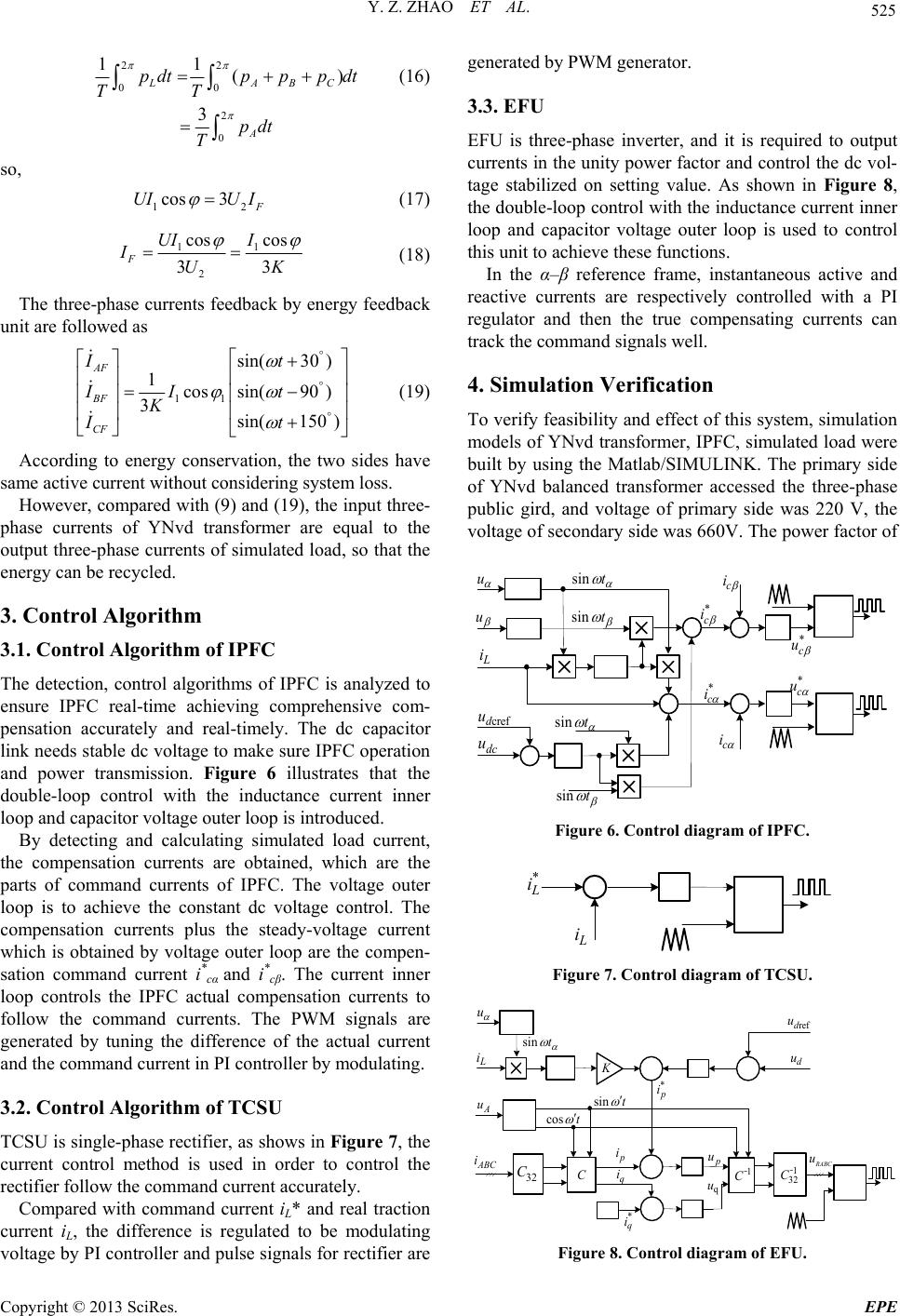 Y. Z. ZHAO ET AL. 525 22 00 2 0 11 ( 3 LAB A pdtppp dt TT pdt T ) C 2 (16) so, 1 cos 3 F UIU I (17) 11 2 cos cos 33 F UI I IUK (18) The three-phase currents feedback by energy feedback unit are followed as 11 sin(30) 1cossin(90 ) 3sin(150 ) AF BF CF It II t Kt I (19) According to energy conservation, the two sides have same active current without considering system loss. However, compared with (9) and (19), the input three- phase currents of YNvd transformer are equal to the output three-phase currents of simulated load, so that the energy can be recycled. 3. Control Algorithm 3.1. Control Algorithm of IPFC The detection, control algorithms of IPFC is analyzed to ensure IPFC real-time achieving comprehensive com- pensation accurately and real-timely. The dc capacitor link needs stable dc voltage to make sure IPFC operation and power transmission. Figure 6 illustrates that the double-loop control with the inductance current inner loop and capacitor voltage outer loop is introduced. By detecting and calculating simulated load current, the compensation currents are obtained, which are the parts of command currents of IPFC. The voltage outer loop is to achieve the constant dc voltage control. The compensation currents plus the steady-voltage current which is obtained by voltage outer loop are the compen- sation command current i* cα and i* cβ. The current inner loop controls the IPFC actual compensation currents to follow the command currents. The PWM signals are generated by tuning the difference of the actual current and the command current in PI controller by modulating. 3.2. Control Algorithm of TCSU TCSU is single-phase rectifier, as shows in Figure 7, the current control method is used in order to control the rectifier follow the command current accurately. Compared with command current iL* and real traction current iL, the difference is regulated to be modulating voltage by PI controller and pulse signals for rectifier are generated by PWM generator. 3.3. EFU EFU is three-phase inverter, and it is required to output currents in the unity power factor and control the dc vol- tage stabilized on setting value. As shown in Figure 8, the double-loop control with the inductance current inner loop and capacitor voltage outer loop is used to control this unit to achieve these functions. In the α–β reference frame, instantaneous active and reactive currents are respectively controlled with a PI regulator and then the true compensating currents can track the command signals well. 4. Simulation Verification To verify feasibility and effect of this system, simulation models of YNvd transformer, IPFC, simulated load were built by using the Matlab/SIMULINK. The primary side of YNvd balanced transformer accessed the three-phase public gird, and voltage of primary side was 220 V, the voltage of secondary side was 660V. The power factor of L i dc u crefd u u sin t u sin t sin t sin t * c i * c i c i c i * c u * c u Figure 6. Control diagram of IPFC. * L i L i Figure 7. Control diagram of TCSU. d u refd u u sin t L i K A u sin t cos t 32 C * q i C p i ABC i q i * p i p u 1 32 C ﹣ 1 C ﹣ q u R ABC u Figure 8. Control diagram of EFU. Copyright © 2013 SciRes. EPE 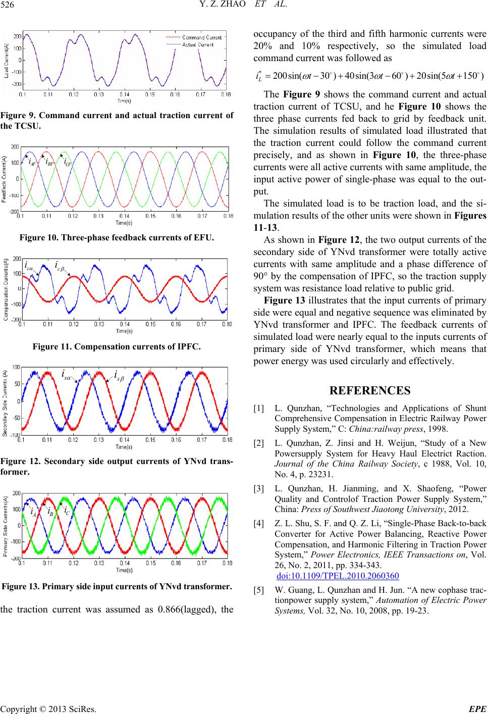 Y. Z. ZHAO ET AL. Copyright © 2013 SciRes. EPE 526 occupancy of the third and fifth harmonic currents were 20% and 10% respectively, so the simulated load command current was followed as *200sin(30 )40sin(360 )20sin(5150 ) L it t t The Figure 9 shows the command current and actual traction current of TCSU, and he Figure 10 shows the three phase currents fed back to grid by feedback unit. The simulation results of simulated load illustrated that the traction current could follow the command current precisely, and as shown in Figure 10, the three-phase currents were all active currents with same amplitude, the input active power of single-phase was equal to the out- put. Figure 9. Command current and actual traction current of the TCSU. AF i B F i CF i The simulated load is to be traction load, and the si- mulation results of the other units were shown in Figures 11-13. Figure 10. Three-phase feedback currents of EFU. As shown in Figure 12, the two output currents of the secondary side of YNvd transformer were totally active currents with same amplitude and a phase difference of 90° by the compensation of IPFC, so the traction supply system was resistance load relative to public grid. c i c i Figure 13 illustrates that the input currents of primary side were equal and negative sequence was eliminated by YNvd transformer and IPFC. The feedback currents of simulated load were nearly equal to the inputs currents of primary side of YNvd transformer, which means that power energy was used circularly and effectively. Figure 11. Compensation currents of IPFC. s i s i REFERENCES [1] L. Qunzhan, “Technologies and Applications of Shunt Comprehensive Compensation in Electric Railway Power Supply System,” C: China:railway press, 1998. [2] L. Qunzhan, Z. Jinsi and H. Weijun, “Study of a New Powersupply System for Heavy Haul Electrict Raction. Journal of the China Railway Society, c 1988, Vol. 10, No. 4, p. 23231. Figure 12. Secondary side output currents of YNvd trans- former. [3] L. Qunzhan, H. Jianming, and X. Shaofeng, “Power Quality and Controlof Traction Power Supply System,” China: Press of Southwest Jiaotong University, 2012. A i B i C i [4] Z. L. Shu, S. F. and Q. Z. Li, “Single-Phase Back-to-back Converter for Active Power Balancing, Reactive Power Compensation, and Harmonic Filtering in Traction Power System,” Power Electronics, IEEE Transactions on, Vol. 26, No. 2, 2011, pp. 334-343. doi:10.1109/TPEL.2010.2060360 Figure 13. Primary side input currents of YNvd trans former. [5] W. Guang, L. Qunzhan and H. Jun. “A new cophase trac- tionpower supply system,” Automation of Electric Power Systems, Vol. 32, No. 10, 2008, pp. 19-23. the traction current was assumed as 0.866(lagged), the |