

Paper Menu >>
Journal Menu >>
 Energy and Power Engineering, 2013, 5, 458-462 doi:10.4236/epe.2013.54B088 Published Online July 2013 (http://www.scirp.org/journal/epe) An Investigation of Scaled-FLC Using PSO for Multi-area Power System Load Frequency Control Aqeel S. Jaber1, A.Z. Ahmad1,2, Ahmed N Abdalla1 1Faculty of Electrical and Electronics Engineering, University Malaysia Pahang, Pekan, Malaysia 2Sustainable En.& Power Elec. Res. (SuPER) Group, University Malaysia Pahang, Pekan, Malaysia Email: [email protected], zahari[email protected], [email protected] Received April, 2013 ABSTRACT Load Frequency Control (LFC) is one of power systems important requirements which maintain the zero steady-state errors in the frequency changing and restoring the natural frequency to its normal position. Many problems are subject to LFC such as suddenly large load or suddenly disconnecting generating unit by the protection device. In this paper, multi-area Frequency Control by using the combination of PSO and fuzzy logic control (FLC) technique. PSO optimi- zation method is used to tuning the fuzzy controller input and output gains. Four of an interconnected electrical power system used as a testing the effectiveness of the proposed method compared to a conventional PI controller and scaled-fuzzy controller. The simulation result has been shown that the controller can generate the best dynamic response in multi-load conditions. Keywords: Fuzzy Control; PSO; Load Frequency Control 1. Introduction One of the major requirements in parallel operation of interconnected power systems is the Load Frequency Control (LFC) which is responsible for scheduled power transfers between the interconnected areas at any distur- bance in the case of the connecting or disconnecting ge- nerating unit or suddenly large load. Various controllers have been used in different areas could not efficiently control the frequency and rather slow for the output re- sponse due to fact of non-linearity in system components [1-2], time invariant and governed by strong cross-couplings of the input variables. Therefore, the controllers have to be designed with taking into account the nonlinearities and disturbances. Many of control methodologies have been suggested to solve LFC problem. Static Output Feedback gains and Linear Matrix Inequality are the most efficient and effec- tive tool which stabilizes the system which used to cal- culate the gains of PID controller [3]. The Robust adap- tive control also has been used to deal with the change in a system parametric [4]. Optimization techniques have been done to solve LFC, but they require information about the entire system rather than local information [5]. Other control approaches such as PID-ANN, PI-fuzzy and optimal control applied to LFC has been reported in [6]. Using genetic algorithm to scale of PI fuzzy control- ler in LFC has been reported in [7]. This paper presents the FLC using PI-fuzzy controllers. The proposed controller is tuned using PSO to obtain the controller gains in order to get an efficient fuzzy control on four of an interconnected electrical power system. This is a new approach to optimize the fuzzy controller that differentiates to other's methods. The simulation results are carried out in term frequency response for its damping under different load conditions and compared it to the effectiveness of proposed controllers with other controllers. Simulation results show that the undershot and settling times with the proposed controller are better and guarantees robust performance under a wide range of operating conditions. 2. Theoretical Background Power systems have multi-variable and complex struc- tures and consist of different control blocks and deal with nonlinear and/or non-minimum phase systems [8]. Power systems are divided into control areas connected by tie lines and all generators are supposed to constitute a co- herent group in each control area. 2.1. Load Frequency Control The aim of LFC is to maintain real power balance in the system through control of system frequency. Small changes in real power are mainly dependent on changes in rotor angle δ and, thus, the frequency f. whenever the Copyright © 2013 SciRes. EPE 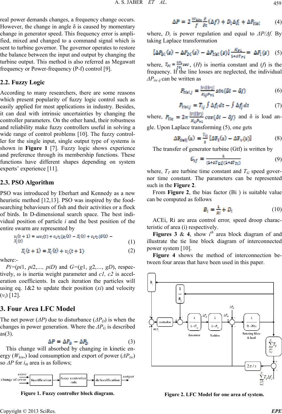 A. S. JABER ET AL. 459 real power demands changes, a frequency change occurs. However, the change in angle δ is caused by momentary change in generator speed. This frequency error is ampli- fied, mixed and changed to a command signal which is sent to turbine governor. The governor operates to restore the balance between the input and output by changing the turbine output. This method is also referred as Megawatt frequency or Power-frequency (P-f) control [9]. 2.2. Fuzzy Logic According to many researchers, there are some reasons which present popularity of fuzzy logic control such as easily applied for most applications in industry. Besides, it can deal with intrinsic uncertainties by changing the controller parameters. On the other hand, their robustness and reliability make fuzzy controllers useful in solving a wide range of control problems [10]. The fuzzy control- ler for the single input, single output type of systems is shown in Figure 1 [7]. Fuzzy logic shows experience and preference through its membership functions. These functions have different shapes depending on system experts’ experience [11]. 2.3. PSO Algorithm PSO was introduced by Eberhart and Kennedy as a new heuristic method [12,13]. PSO was inspired by the food- searching behaviours of fish and their activities or a flock of birds. In D-dimensional search space. The best indi- vidual position of particle i and the best position of the entire swarm are represented by (1) (2) where:- Pi=(pi1, pi2,…, piD) and G=(g1, g2,…, gD), respec- tively, ω is inertia weight parameter and c1, c2 is accel- eration coefficients. In each iteration the particles will using eq. 1&2 to update their position (xi) and velocity (vi) [12]. 3. Four Area LFC Model The net power (ΔP) due to disturbance (ΔPD) is when the changes in power generation. Where the ΔPG is described as(3). (3) This change will absorbed by changing in kinetic en- ergy (Wkin,) load consumption and export of power (ΔPtie) so ΔP for ith area is as follows; Figure 1. Fuzzy controller block diagram. (4) where, Di is power regulation and equal to ΔP/Δf. By taking Laplace transformation (5) where, , (H) is inertia constant and (f) is the frequency. If the line losses are neglected, the individual ΔPtie ij can be written as (6) (7) where, and δ is load an- gle. Upon Laplace transforming (5), one gets (8) The transfer of generator turbine (Gtf) is written by (9) where, TT are turbine time constant and TG speed gover- nor time constant. The parameters can be represented such in the Figure 2. From Figure 2, the bias factor (Bi ) is suitable value can be computed as follows (10) ACEi, Ri are area control error, speed droop charac- teristic of area (i) respectively. Figures 3 & 4, show ith area block diagram of and illustrate the tie line block diagram of interconnected power system [10]. Figure 4 shows the method of interconnection be- tween four areas that have been used in this paper. Figure 2. LFC Model for one area of system. Copyright © 2013 SciRes. EPE 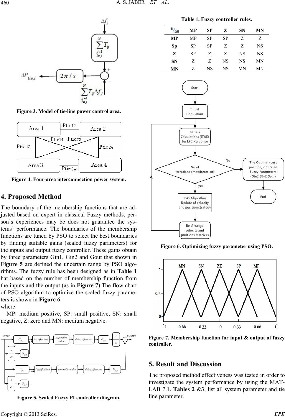 A. S. JABER ET AL. 460 Figure 3. Model of tie-line power control are a. Figure 4. Four-area interconnection power system. 4. Proposed Method bership functions that are ad- dium positive, SP: small positive, SN: small ne The boundary of the mem justed based on expert in classical Fuzzy methods, per- son’s experiences may be does not guarantee the sys- tems’ performance. The boundaries of the membership functions are tuned by PSO to select the best boundaries by finding suitable gains (scaled fuzzy parameters) for the inputs and output fuzzy controller. These gains obtain by three parameters Gin1, Gin2 and Gout that shown in Figure 5 are defined the uncertain range by PSO algo- rithms. The fuzzy rule has been designed as in Table 1 hat based on the number of membership function from the inputs and the output (as in Figure 7).The flow chart of PSO algorithm to optimize the scaled fuzzy parame- ters is shown in Figure 6. where: MP: me gative, Z: zero and MN: medium negative. Table 1. Fuzzy controller rules. MP SP Z SN MN MP MP SP SP Z Z Sp SP SP Z Z NS Z SP Z Z NS NS SN Z Z NS NS MN MN Z NS NS MN MN Figure 6. Optimizing fuzzy parameter using PSO. Figure 7. Member ship function for input & output of fu 5. Result and Discussion ess was tested in order to zzy controller. The proposed method effectiven investigate the system performance by using the MAT- LAB 7.1. Tables 2 &3, list all system parameter and tie line parameter. Figure 5. Scaled Fuzzy PI controller diagram. Copyright © 2013 SciRes. EPE 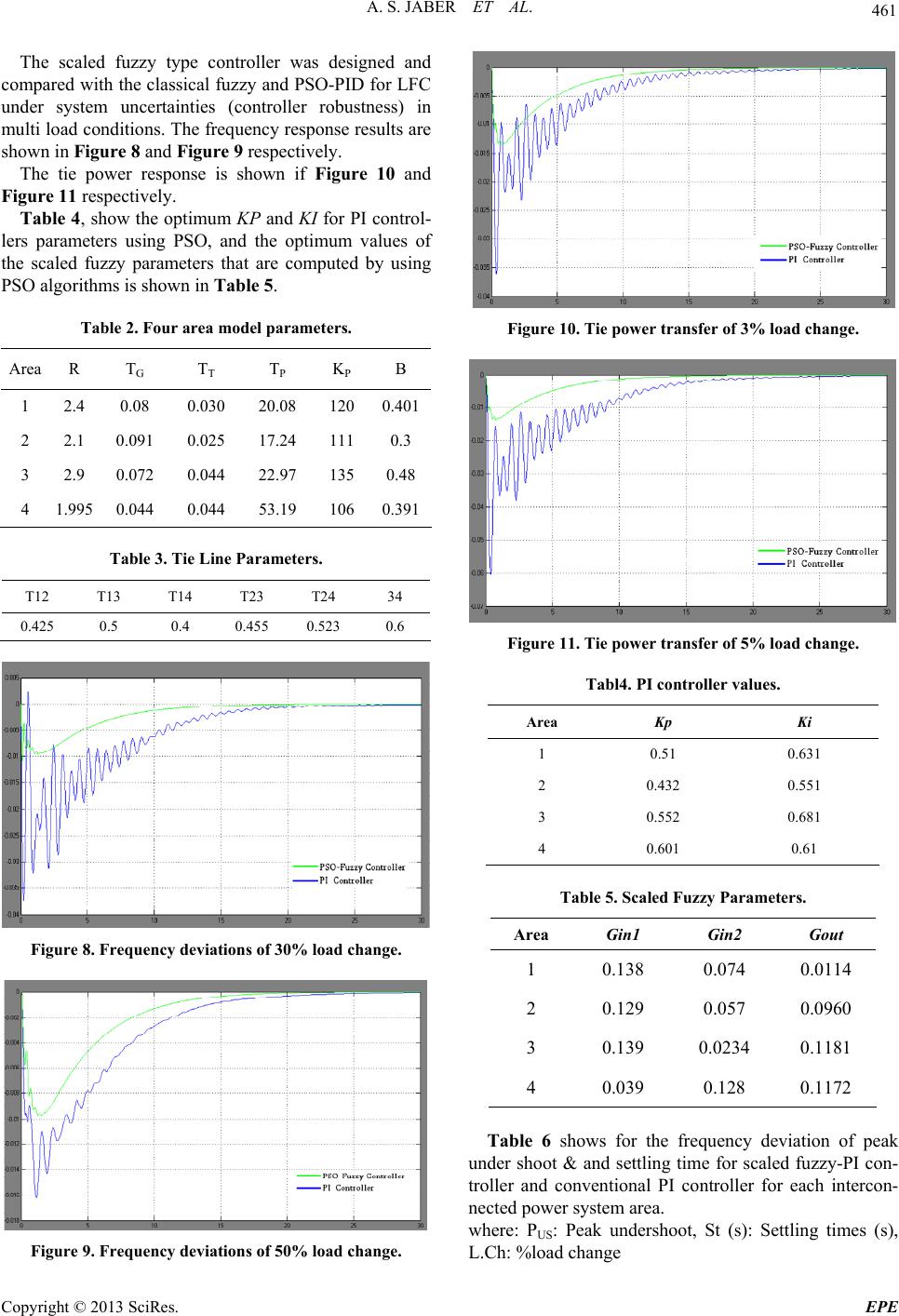 A. S. JABER ET AL. 461 The scaled fuzzy type controller was designed and co re 10 and Fi mum KP and KI for PI control- le Table 2. Four area model parameters. Area R TG T T T P K P B mpared with the classical fuzzy and PSO-PID for LFC under system uncertainties (controller robustness) in multi load conditions. The frequency response results are shown in Figure 8 and Figure 9 respectively. The tie power response is shown if Figu gure 11 respectively. Table 4, show the opti rs parameters using PSO, and the optimum values of the scaled fuzzy parameters that are computed by using PSO algorithms is shown in Table 5. 1 2.4 0.08 0.030 20.08 1200.401 2 2.1 0.091 0.025 17.24 1110.3 3 2.9 0.072 0.044 22.97 1350.48 1 4 .9950.044 0.044 53.19 1060.391 Table 3. Tie Line Parameters. T12 T13 34 T14 T23 T24 0.425 0.5 0.4 0.455 0.523 0.6 Figure 8. Frequency deviations of 30% load change. Figure 10. Tie power transfer of 3% load change. Figure 11. Tie power transfer of 5% load change. Tabl4. PI controller values. Area Kp Ki 1 0.51 0.631 2 0.432 0.551 3 0.552 0.681 4 0.601 0.61 Table 5. Scaled Fuzzy Parameters. Area Gin1 Gin2 Gout 1 0.138 0.0. 074 0114 2 0.129 0.057 0.0960 3 0.139 0.0234 0.1181 4 0.039 0.128 0.1172 Table 6 shows for the frequency deviation of peak un ot, St (s): Settling times (s), der shoot & and settling time for scaled fuzzy-PI con- troller and conventional PI controller for each intercon- nected power system area. where: PUS: Peak undersho Figure 9. Frequency deviations of 50% load change. L.Ch: %load change Copyright © 2013 SciRes. EPE 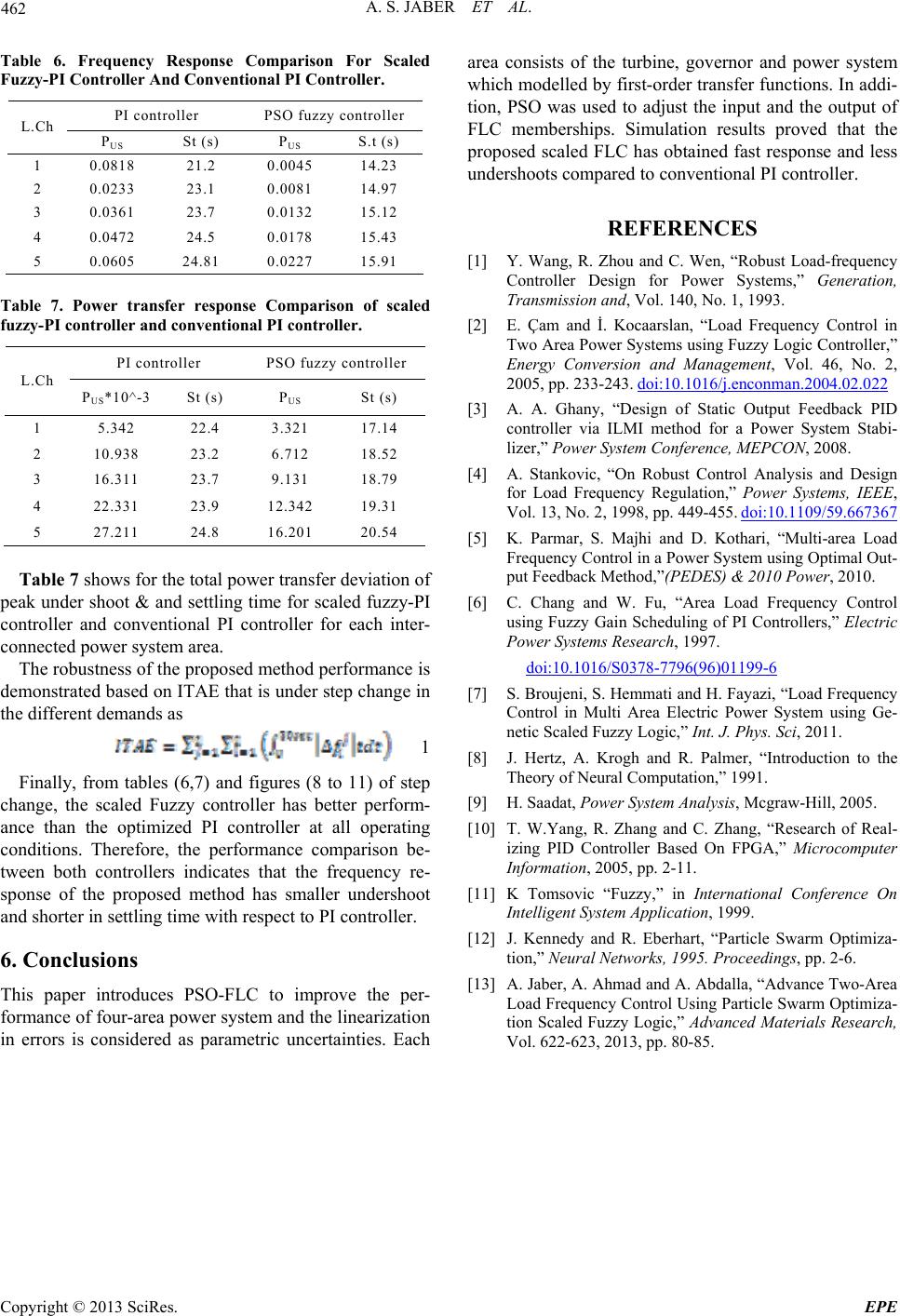 A. S. JABER ET AL. Copyright © 2013 SciRes. EPE 462 Response Comparison For Scaled Table 6. Frequency Fuzzy-PI Controller And Conventional PI Controller. PI controller PSO fuzzy controller L.Ch Ps) US St (PUS S.t (s) 1 0. 0 0818 21.2 .004514.23 2 0.0233 23.1 0.0081 14.97 3 0.0361 23.7 0.0132 15.12 4 0.0472 24.5 0.0178 15.43 5 0.0605 24.81 0.0227 15.91 able 7. Power transfer response Comparison of scaled oller T fuzzy-PI controller and conventional PI controller. PI controller PSO fuzzy contr L.Ch PUS*1 US 0^-3 St (s) P St (s) 1 3 5.342 22.4 .32117.14 2 10.938 23.2 6.712 18.52 3 16.311 23.7 9.131 18.79 4 22.331 23.9 12.342 19.31 5 27.211 24.8 16.201 20.54 Table 7 shows for the total power transfer deviation of pe d method performance is de ak under shoot & and settling time for scaled fuzzy-PI controller and conventional PI controller for each inter- connected power system area. The robustness of the propose monstrated based on ITAE that is under step change in the different demands as 1 Finally, from tables (6,7) and figures (8 to 11) of ch 6. Conclusions ces PSO-FLC to improve the step ange, the scaled Fuzzy controller has better perform- ance than the optimized PI controller at all operating conditions. Therefore, the performance comparison be- tween both controllers indicates that the frequency re- sponse of the proposed method has smaller undershoot and shorter in settling time with respect to PI controller. This paper introduper- formance of four-area power system and the linearization in errors is considered as parametric uncertainties. Each area consists of the turbine, governor and power system which modelled by first-order transfer functions. In addi- tion, PSO was used to adjust the input and the output of FLC memberships. Simulation results proved that the proposed scaled FLC has obtained fast response and less undershoots compared to conventional PI controller. REFERENCES [1] Y. Wang, R. Zhou and C. Wen, “Robust Load-frequency Controller Design for Power Systems,” Generation, Transmission and, Vol. 140, No. 1, 1993. [2] E. Çam and İ. Kocaarslan, “Load Frequency Control in Two Area Power Systems using Fuzzy Logic Controller,” Energy Conversion and Management, Vol. 46, No. 2, 2005, pp. 233-243. doi:10.1016/j.enconman.2004.02.022 [3] A. A. Ghany, “Design of Static Output Feedback PID controller via ILMI method for a Power System Stabi- lizer,” Power System Conference, MEPCON, 2008. [4] A. Stankovic, “On Robust Control Analysis and Design for Load Frequency Regulation,” Power Systems, IEEE, Vol. 13, No. 2, 1998, pp. 449-455. doi:10.1109/59.667367 [5] K. Parmar, S. Majhi and D. Kothari, “Multi-area Load Frequency Control in a Power System using Optimal Out- put Feedback Method,”(PEDES) & 2010 Power, 2010. [6] C. Chang and W. Fu, “Area Load Frequency Control using Fuzzy Gain Scheduling of PI Controllers,” Electric Power Systems Research, 1997. doi:10.1016/S0378-7796(96)01199-6 [7] S. Broujeni, S. Hemmati and H. Fayazi, “Load Frequency Control in Multi Area Electric Power System using Ge- netic Scaled Fuzzy Logic,” Int. J. Phys. Sci, 2011. [8] J. Hertz, A. Krogh and R. Palmer, “Introduction to the Theory of Neural Computation,” 1991. [9] H. Saadat, Power System Analysis, Mcgraw-Hill, 2005. [10] T. W.Yang, R. Zhang and C. Zhang, “Research of Real- izing PID Controller Based On FPGA,” Microcomputer Information, 2005, pp. 2-11. [11] K Tomsovic “Fuzzy,” in International Conference On Intelligent System Application, 1999. [12] J. Kennedy and R. Eberhart, “Particle Swarm Optimiza- tion,” Neural Networks, 1995. Proceedings, pp. 2-6. [13] A. Jaber, A. Ahmad and A. Abdalla, “Advance Two-Area Load Frequency Control Using Particle Swarm Optimiza- tion Scaled Fuzzy Logic,” Advanced Materials Research, Vol. 622-623, 2013, pp. 80-85. |