

Paper Menu >>
Journal Menu >>
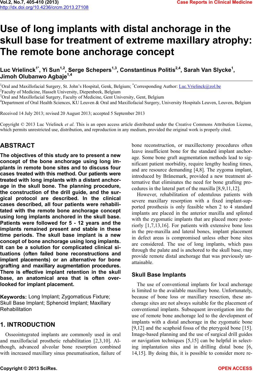 Vol.2, No.7, 405-410 (2013) Case Reports in Clinical Medicine http://dx.doi.org/10.4236/crcm.2013.27108 Copyright © 2013 SciRes. OPEN ACCESS Use of long implants with distal anchorage in the skull base for treatment of extreme maxillary atrophy: The remote bone anchorage concept Luc Vrielinck1*, Y i Sun1,2, Serge Schepers1,3, Constantinus Politis2,4, Sarah Van Slycke1, Jimoh Olubanwo Agbaje1,4 1Oral and Maxillofacial Surgery, St. John’s Hospital, Genk, Belgium; *Corresponding Author: [email protected] 2Faculty of Medicine, Hasselt University, Diepenbeek, Belgium 3Oral and Maxillofacial Surgery, Faculty of Medicine, Gent University, Gent, Belgium 4Department of Oral Health Sciences, KU Leuven & Oral and Maxillofacial Surgery, University Hospitals Leuven, Leuven, Belgium Received 14 July 2013; revised 20 August 2013; accepted 5 September 2013 Copyright © 2013 Luc Vrielinck et al. This is an open access article distributed under the Creative Commons Attribution License, which permits unrestricted use, distribution, and reproduction in any medium, provided the original work is properly cited. ABSTRACT The objectives of t his s t udy are to present a new concept of the bone anchorage using long im- plants in remote bone sites and to discuss four cases treated with this method. Our patients were treated with long implants with a distant anchor- age in the skull bone. The planning procedure, the construction of the drill guide, and the sur- gical protocol are described. In the clinical cases described, all four patients were rehabili- tated with the remote bone anchorage concept using long implants anchored in the skull base. Patients were followed for 5 - 12 years and the implants remained present and stable in these time periods. The skull base implant is a new concept of bone anchorage using long implants. It can be a solution for complicated clinical si- tuations (often failed bone reconstructions and implant placements) or an alternative for bone grafting and maxillary augmentation procedures. There is effective implant retention in the skull base, an anatomical area that is often over- looked for implant placement. Keywords: Long Implant; Zygomaticus Fixture; Skull Base Implant; Sphenoid Implant; Maxillary Rehabilitation 1. INTRODUCTION Osseointegrated implants are commonly used in oral and maxillofacial prosthetic rehabilitation [2,3,10]. Al- though, advanced alveolar bone resorption combined with increased maxillary sinus pn eumatisation, failure of bone reconstruction, or maxillectomy procedures often leave insufficient bone for the standard implant anchor- age. Some bone graft augmentation methods lead to sig- nificant patient morbidity, require lengthy healing times, and are resource demanding [4,8]. The zygoma implant, introduced by Brånemark, provided a new treatment al- ternative that eliminates the need for bone grafting pro- cedures in the lateral part of the maxilla [8,9,11,12]. However, rehabilitation of edentulous patients with severe maxillary resorption with a fixed implant-sup- ported prosthesis is only feasible when 2 to 4 standard implants are placed in the anterior maxilla and splinted with the zygomatic implants that are placed more poste- riorly [1,7,13,16]. For patients with extensive bone loss in the pre-maxilla and lateral bones, implant placement in defect areas is compromised unless other bone sites are considered. The use of long implants, which pass through the p alate and is anchored to th e skull base, may provide remote distal anchorage that was previously un- attainable. Skull Base Implants The use of conventional implants for local anchorage is limited to the available maxillary bone. Unfortunately, because of bone loss or maxillary resection, these an- chorage sites are not always suitable for the placement of conventional implants. Subsequent investigation into the use of remote bone anchorage led to the development of implants with a distal anchorage in the zygomatic bone [9,12] and the scaphoid fossa of th e pterygoid bone [15]. Image-based planning and the use of surgical drill guides or navigation techniques [5,15] can be helpful in select- ing implantation sites and in drilling distal bone [6, 14,15]. By doing this, it is possible to consider more re- 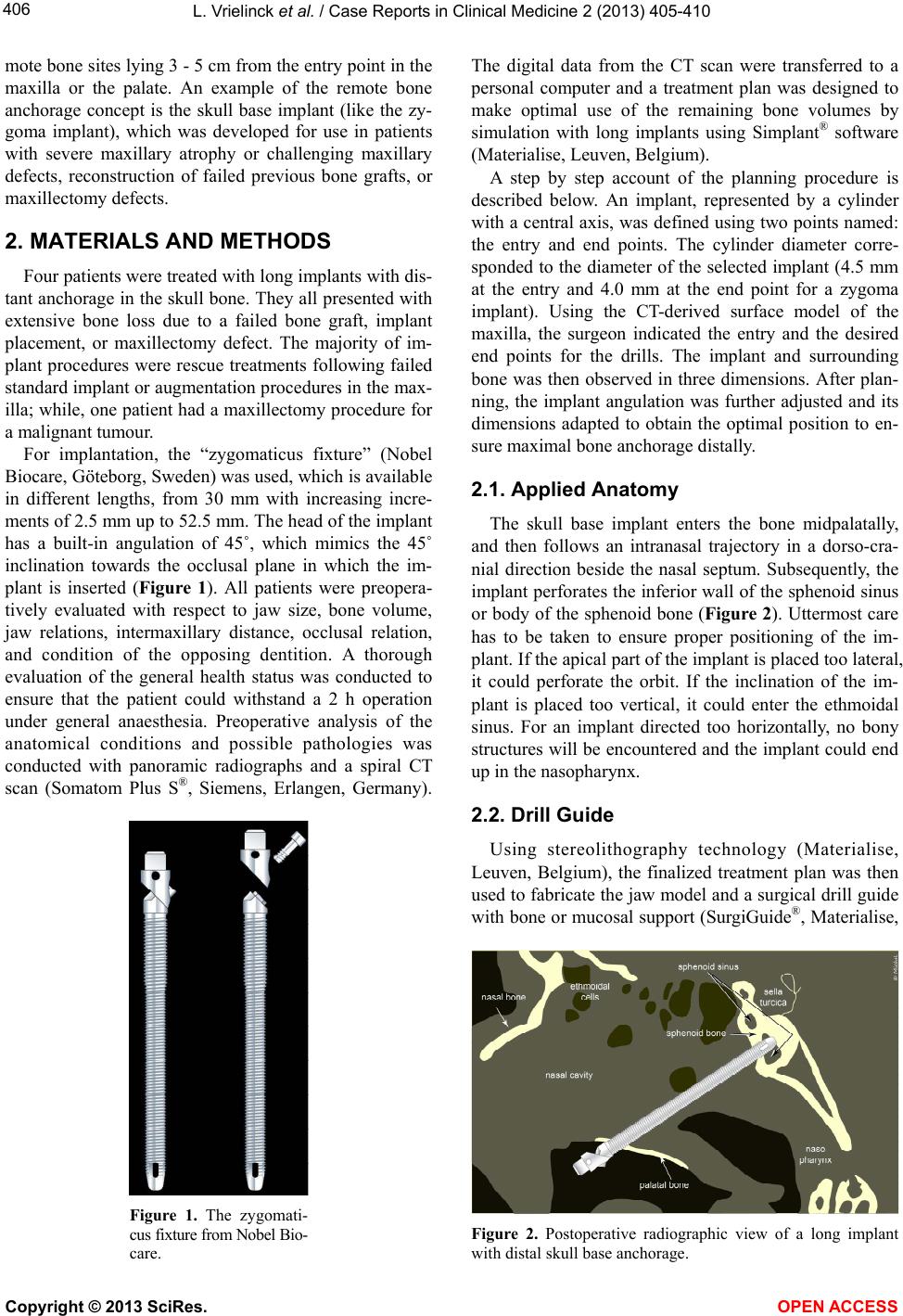 L. Vrielinck et al. / Case Reports in Clinical Medicine 2 (2013) 405-410 Copyright © 2013 SciRes. OPEN ACCESS 406 mote bone sites lying 3 - 5 cm from the entry point in the maxilla or the palate. An example of the remote bone anchorage concept is the skull base implant (like the zy- goma implant), which was developed for use in patients with severe maxillary atrophy or challenging maxillary defects, reconstruction of failed previous bone grafts, or maxillectomy defects. 2. MATERIALS AND METHODS Four patients were treated with long implants with dis- tant anchorage in the skull bone. They all presented with extensive bone loss due to a failed bone graft, implant placement, or maxillectomy defect. The majority of im- plant procedures were rescue treatments following failed standard implant or augmentation procedures in the max- illa; while, one patient h ad a maxillectomy procedure for a malignant tumour. For implantation, the “zygomaticus fixture” (Nobel Biocare, Göteborg, Sweden) was used, which is av ailab le in different lengths, from 30 mm with increasing incre- ments of 2.5 mm up to 52.5 mm. The head of the implant has a built-in angulation of 45˚, which mimics the 45˚ inclination towards the occlusal plane in which the im- plant is inserted (Figure 1). All patients were preopera- tively evaluated with respect to jaw size, bone volume, jaw relations, intermaxillary distance, occlusal relation, and condition of the opposing dentition. A thorough evaluation of the general health status was conducted to ensure that the patient could withstand a 2 h operation under general anaesthesia. Preoperative analysis of the anatomical conditions and possible pathologies was conducted with panoramic radiographs and a spiral CT scan (Somatom Plus S®, Siemens, Erlangen, Germany). Figure 1. The zygomati- cus fixture from Nobel Bio- care. The digital data from the CT scan were transferred to a personal computer and a treatment plan was designed to make optimal use of the remaining bone volumes by simulation with long implants using Simplant® software (Materialise, Leuven, Belgium). A step by step account of the planning procedure is described below. An implant, represented by a cylinder with a central axis, was defined using two points named: the entry and end points. The cylinder diameter corre- sponded to the diameter of the selected implant (4.5 mm at the entry and 4.0 mm at the end point for a zygoma implant). Using the CT-derived surface model of the maxilla, the surgeon indicated the entry and the desired end points for the drills. The implant and surrounding bone was then observed in three dimensions. After plan- ning, the implant angulation was further adjusted and its dimensions adapted to obtain the optimal position to en- sure maximal bone anchorage distally. 2.1. Applied Anatomy The skull base implant enters the bone midpalatally, and then follows an intranasal trajectory in a dorso-cra- nial direction beside the nasal septum. Subsequently, the implant perforates the inferior wall of the sphenoid sinu s or body of the sphenoid bone (Figure 2). Uttermost care has to be taken to ensure proper positioning of the im- plant. If the apical part of the implant is placed too lateral, it could perforate the orbit. If the inclination of the im- plant is placed too vertical, it could enter the ethmoidal sinus. For an implant directed too horizontally, no bony structures will be encountered and th e implant could end up in the nasopharynx. 2.2. Drill Guide Using stereolithography technology (Materialise, Leuven, Belgium), the finalized treatment plan was then used to fabricate the jaw model and a surgical drill guide with bone or mucosal support (SurgiGuide®, Materialise, Figure 2. Postoperative radiographic view of a long implant with distal skull base anchorage. 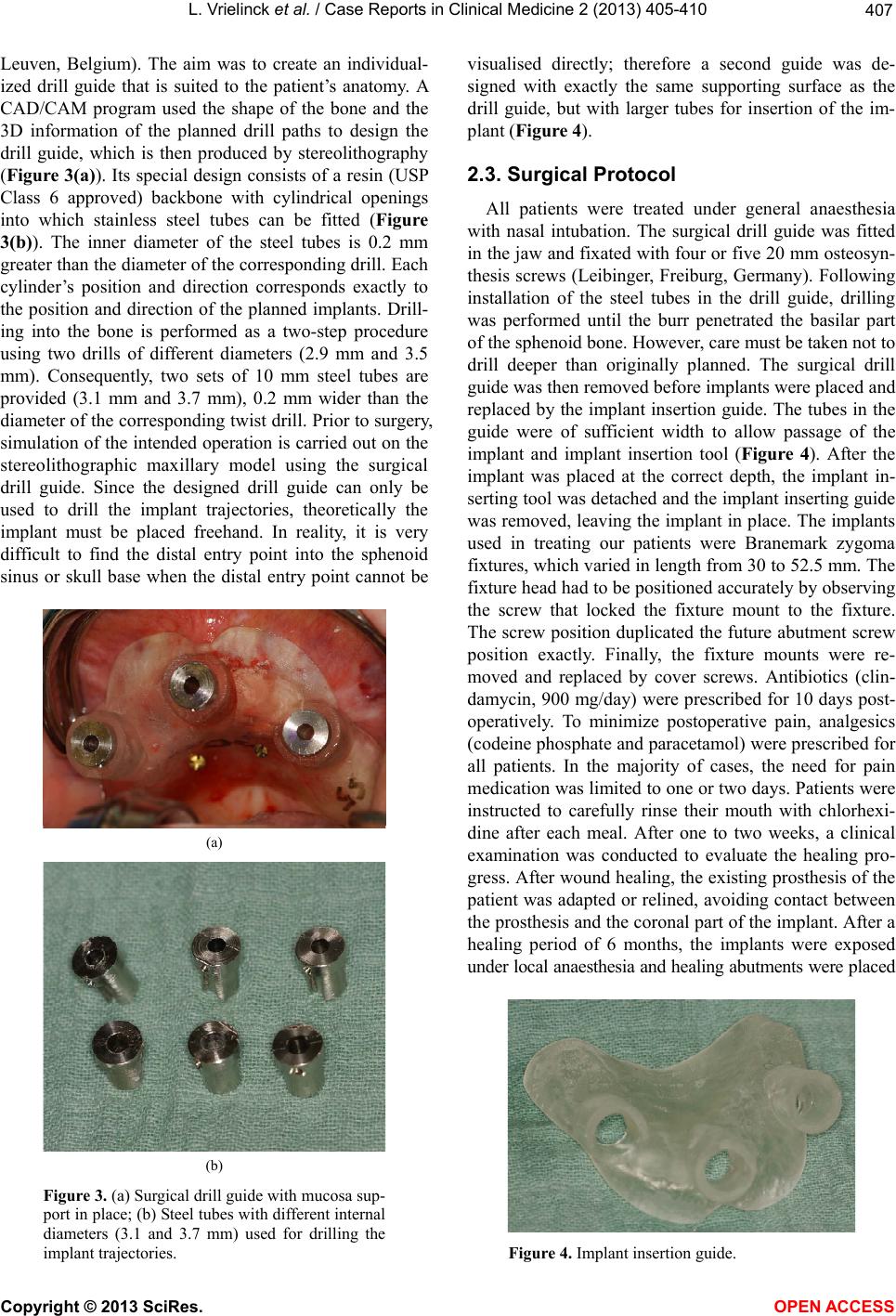 L. Vrielinck et al. / Case Reports in Clinical Medicine 2 (2013) 405-410 Copyright © 2013 SciRes. OPEN ACCESS 407 Leuven, Belgium). The aim was to create an individual- ized drill guide that is suited to the patient’s anatomy. A CAD/CAM program used the shape of the bone and the 3D information of the planned drill paths to design the drill guide, which is then produced by stereolithography (Figure 3(a)). Its special design consists of a resin (USP Class 6 approved) backbone with cylindrical openings into which stainless steel tubes can be fitted (Figure 3(b)). The inner diameter of the steel tubes is 0.2 mm greater than the diameter of the corresp onding drill. Each cylinder’s position and direction corresponds exactly to the position and direction of the planned implants. Drill- ing into the bone is performed as a two-step procedure using two drills of different diameters (2.9 mm and 3.5 mm). Consequently, two sets of 10 mm steel tubes are provided (3.1 mm and 3.7 mm), 0.2 mm wider than the diameter of the corresponding twist drill. Prior to surgery, simulation of the intended operation is carried out on the stereolithographic maxillary model using the surgical drill guide. Since the designed drill guide can only be used to drill the implant trajectories, theoretically the implant must be placed freehand. In reality, it is very difficult to find the distal entry point into the sphenoid sinus or skull base when the distal entry point cannot be (a) (b) Figure 3. (a) Surgical drill guide with mucosa sup- port in place; (b) Steel tubes with different internal diameters (3.1 and 3.7 mm) used for drilling the implant trajector ies. visualised directly; therefore a second guide was de- signed with exactly the same supporting surface as the drill guide, but with larger tubes for insertion of the im- plant (Figure 4). 2.3. Surgical Protocol All patients were treated under general anaesthesia with nasal intubation. The surgical drill guide was fitted in the jaw and fixated with four or five 20 mm osteosyn- thesis screws (Leibinger, Freiburg, Germany). Following installation of the steel tubes in the drill guide, drilling was performed until the burr penetrated the basilar part of the spheno id bone. Ho wever, care must be taken not to drill deeper than originally planned. The surgical drill guide was then removed before implants were placed and replaced by the implant insertion guide. The tubes in the guide were of sufficient width to allow passage of the implant and implant insertion tool (Figure 4). After the implant was placed at the correct depth, the implant in- serting tool was detached and the implant inserting guide was removed, leaving the implant in place. The implants used in treating our patients were Branemark zygoma fixtures, which varied in length from 30 to 52.5 mm. The fixture head had to b e p os itioned accurately by ob serving the screw that locked the fixture mount to the fixture. The screw position duplicated the future abutment screw position exactly. Finally, the fixture mounts were re- moved and replaced by cover screws. Antibiotics (clin- damycin, 900 mg/day) were prescribed for 10 days post- operatively. To minimize postoperative pain, analgesics (codeine phosphate and paracetamol) were prescribed for all patients. In the majority of cases, the need for pain medication was limited to one or two days. Patients were instructed to carefully rinse their mouth with chlorhexi- dine after each meal. After one to two weeks, a clinical examination was conducted to evaluate the healing pro- gress. After wound healing, the existing prosthesis of th e patient was adapted or relined, avoiding contact between the prosthesis and the coronal part of the implant. After a healing period of 6 months, the implants were exposed under local anaesthesia and healing abutments were placed Figure 4. Implant insertion guide. 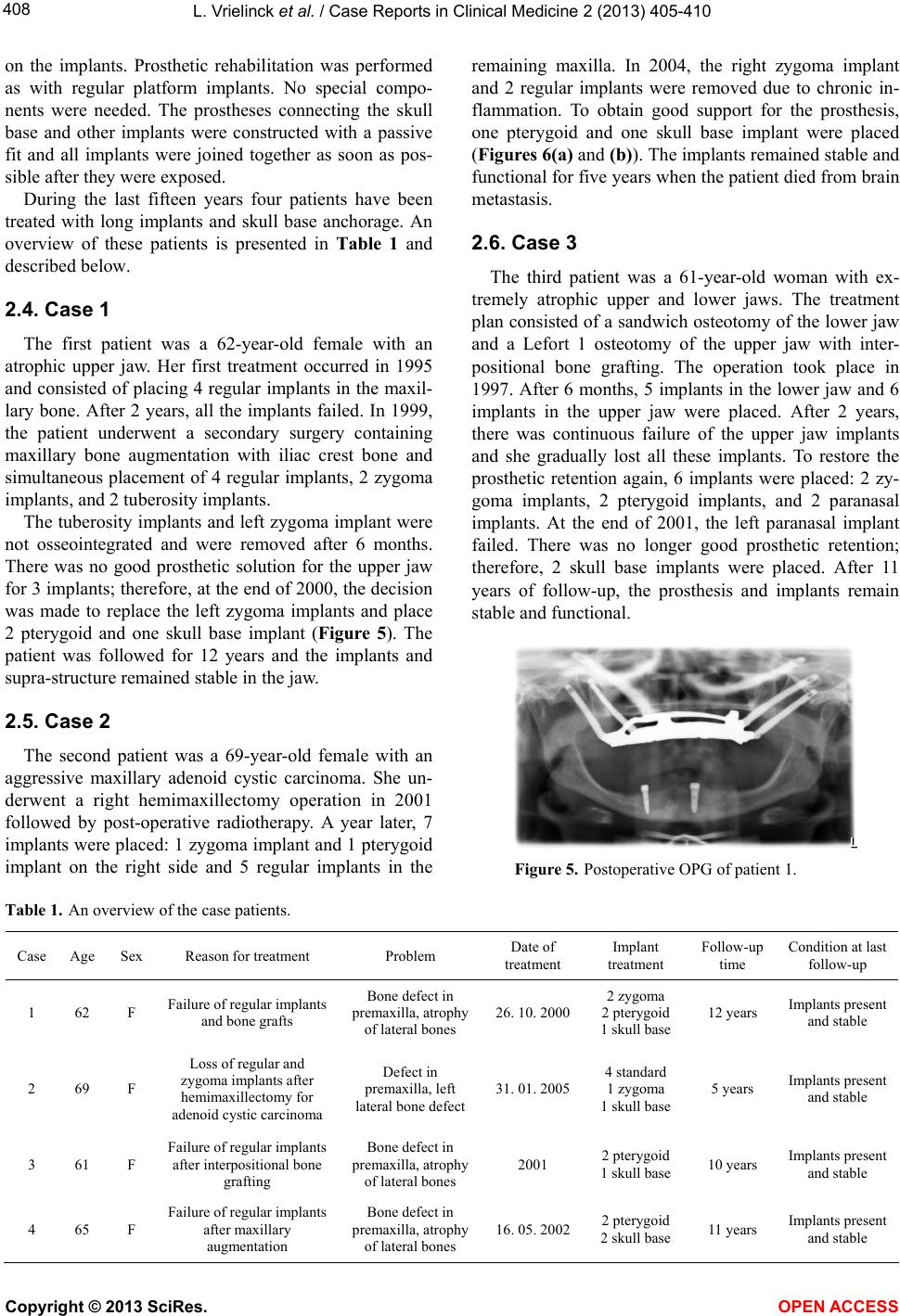 L. Vrielinck et al. / Case Reports in Clinical Medicine 2 (2013) 405-410 Copyright © 2013 SciRes. OPEN ACCESS 408 on the implants. Prosthetic rehabilitation was performed as with regular platform implants. No special compo- nents were needed. The prostheses connecting the skull base and other implants were constructed with a passive fit and all implants were joined together as soon as pos- sible after they were exposed. During the last fifteen years four patients have been treated with long implants and skull base anchorage. An overview of these patients is presented in Table 1 and described below. 2.4. Case 1 The first patient was a 62-year-old female with an atrophic upper jaw. Her first treatment occurred in 1995 and consisted of placing 4 regular implants in the maxil- lary bone. After 2 years, all the implants failed. In 1999, the patient underwent a secondary surgery containing maxillary bone augmentation with iliac crest bone and simultaneous placement of 4 regular implants, 2 zygoma implants, and 2 tuberosity implants. The tuberosity implants and left zygoma implant were not osseointegrated and were removed after 6 months. There was no good prosthetic solution for the upper jaw for 3 implants; therefor e, at the end of 2000, the decision was made to replace the left zygoma implants and place 2 pterygoid and one skull base implant (Figure 5). The patient was followed for 12 years and the implants and supra-structure remained stab le in the jaw. 2.5. Case 2 The second patient was a 69-year-old female with an aggressive maxillary adenoid cystic carcinoma. She un- derwent a right hemimaxillectomy operation in 2001 followed by post-operative radiotherapy. A year later, 7 implants were placed: 1 zygoma implant and 1 pterygoid implant on the right side and 5 regular implants in the remaining maxilla. In 2004, the right zygoma implant and 2 regular implants were removed due to chronic in- flammation. To obtain good support for the prosthesis, one pterygoid and one skull base implant were placed (Figures 6(a) and (b)). The implants remained stable and functional for five years when the patient died from brain metastasis. 2.6. Case 3 The third patient was a 61-year-old woman with ex- tremely atrophic upper and lower jaws. The treatment plan consisted of a sandwich osteotomy of the lower jaw and a Lefort 1 osteotomy of the upper jaw with inter- positional bone grafting. The operation took place in 1997. After 6 months, 5 implants in the lower jaw and 6 implants in the upper jaw were placed. After 2 years, there was continuous failure of the upper jaw implants and she gradually lost all these implants. To restore the prosthetic retention again, 6 implants were placed: 2 zy- goma implants, 2 pterygoid implants, and 2 paranasal implants. At the end of 2001, the left paranasal implant failed. There was no longer good prosthetic retention; therefore, 2 skull base implants were placed. After 11 years of follow-up, the prosthesis and implants remain stable and functional. Figure 5. Postoperative OPG of patient 1. Table 1. An overview of the case patients. Case Age Sex Reason for treatment Problem Date of treatment Implant treatment Follow-up time Condition at last follow-up 1 62 F Failure of regular implants and bone grafts Bone defect in premaxilla, atrophy of lateral bones 26. 10. 20002 zygoma 2 pterygoid 1 skull base 12 years Implants present and stable 2 69 F Loss of regular and zygoma implants after hemimaxillectomy for adenoid cystic carcinoma Defect in premaxilla, left lateral bone defect 31. 01. 20054 standard 1 zygoma 1 skull base 5 years Implants present and stable 3 61 F Failure of regular implants after interpositional bone grafting Bone defect in premaxilla, atrophy of lateral bones 2001 2 pterygoid 1 skull base 10 years Implants present and stable 4 65 F Failure of regular implants after maxillary augmentation Bone defect in premaxilla, atrophy of lateral bones 16. 05. 20022 pterygoid 2 skull base 11 years Implants present and stable 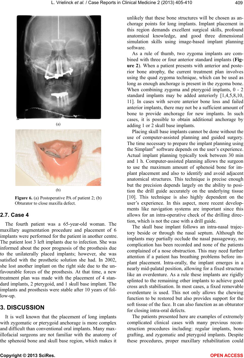 L. Vrielinck et al. / Case Reports in Clinical Medicine 2 (2013) 405-410 Copyright © 2013 SciRes. OPEN ACCESS 409 (a) (b) Figure 6. (a) Postoperative PA of patient 2; (b) Obturator to close maxilla defect. 2.7. Case 4 The fourth patient was a 65-year-old woman. The maxillary augmentation procedure and placement of 6 implants were performed for the patient in another centre. The patient lost 3 left implants due to in fection. She was informed about the poor prognosis of the prosthesis due to the unilaterally placed implants; however, she was satisfied with the prosthetic solution she had. In 2002, she lost another implant on the right side due to the un- favourable forces of the prosthesis. At that time, a new treatment plan was made with the placement of 4 stan- dard implants, 2 pterygoid, and 1 skull base implant. The implants and prosthesis were stable after 10 years of fol- low-up. 3. DISCUSSION It is well known that the placement of long implants with zygomatic or pterygoid anchorage is more complex and difficult than conven tional oral implants. Man y max- illofacial surgeons are not familiar with the anatomy of the sphenoid bone and skull base region, which makes it unlikely that these bone structures will be chosen as an- chorage points for long implants. Implant placement in this region demands excellent surgical skills, profound anatomical knowledge, and good three dimensional simulation skills using image-based implant planning software. As a rule of thumb, two zygoma implants are com- bined with three or four anterior standard implants (Fig- ure 2). When a patient presents with anterior and poste- rior bone atrophy, the current treatment plan involves using the quad zygoma technique, which can be used as long as enough anch orage is present in th e zygoma bone. When combining zygoma and pterygoid implants, 0 - 2 standard implants may be added anteriorly [1,4,5,8,10, 11]. In cases with severe anterior bone loss and failed anterior implants, there may not be a sufficient amount of bone to provide anchorage for new implants. In such cases, it is possible to obtain additional anchorage by adding 1 or 2 skull base implants. Placing skull base implants cannot be done without the use of computer-assisted planning and guided surgery. The time necessary to prepare the implant planning using the Simplant® software depends on the user ’s experience. Actual implant planning typically took between 30 min and 1 h. Computer-assisted planning allows the surgeon to use the maximum amount of sphenoid bone for im- plant placement and also to identify and avoid adjacent anatomical structures. This technique is precise enough but the precision depends largely on the ability to posi- tion the drill guide accurately on the underlying tissue [10]. This technique is also highly dependent on the user’s experience. In this aspect, more recent develop- ments like navigation systems are important since this allows for an intra-operative check of the drilling direc- tion, which is not the case with a drill guide. The skull base implant follows an intra-nasal trajec- tory beside or through the nasal septum. Although the implants may partially occlude the nasal passageway, no complication has been recorded and none of the patients complained of a nose obstruction. This may need further attention if a patient has breathing problems before im- plant placement. Intra-orally, the implant emerges in a nearly mid-palatal position, allo wing for a fixed structure like an overdenture. As a rule these implants are rigidly splinted to the remaining other implants to achieve good cross arch stabilisation. In most cases, a fixed removable overdenture is used. This not only allows the chewing function to be restored but also provides support for the soft tissue of the face. It can also function as an obturator for closing intra-oral defects. The patients presented here are examples of extremely complicated clinical cases with many previous recon- struction procedures including: regular implants, bone grafting, and zygomatic and pterygoid implants. Despite these procedures, proper maxillary rehabilitation could 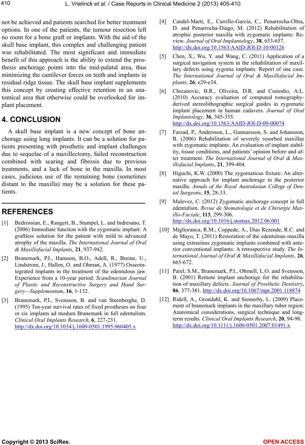 L. Vrielinck et al. / Case Reports in Clinical Medicine 2 (2013) 405-410 Copyright © 2013 SciRes. OPEN ACCESS 410 not be achieve d and patie nts searched for bett er treatment options. In one of the patients, the tumour resection left no room for a bone graft or implants. With the aid of the skull base implant, this complex and challenging patient was rehabilitated. The most significant and immediate benefit of this approach is the ability to extend the pros- thesis anchorage points into the mid-palatal area, thus minimizing the can tilever forces on teeth and implants in residual ridge tissue. The skull base implant supplements this concept by creating effective retention in an ana- tomical area that otherwise could be overlooked for im- plant placement. 4. CONCLUSION A skull base implant is a new concept of bone an- chorage using long implants. It can be a solution for pa- tients presenting with prosthetic and implant challenges due to sequelae of a maxillectomy, failed reconstruction combined with scaring and fibrosis due to previous treatments, and a lack of bone in the maxilla. In most cases, judicious use of the remaining bone (sometimes distant to the maxilla) may be a solution for these pa- tients. REFERENCES [1] Bedrossian, E., Rangert, B. , Stumpel, L. and Indresano, T. (2006) Immediate function with the zygomatic implant: A graftless solution for the patient with mild to advanced atrophy of the maxilla. The International Journal of Oral & Maxillofacial Implants, 21, 937-942. [2] Branemark, P.I., Hansson, B.O., Adell, R., Breine, U., Lindstrom, J., Hallen, O. and Ohman, A. (1977) Osseoin- tegrated implants in the treatment of the edentulous jaw. Experience from a 10-year period. Scandinavian Journal of Plastic and Reconstructive Surgery and Hand Sur- gery—Supplementum, 16, 1-132. [3] Branemark, P.I., Svensson, B. and van Steenberghe, D. (1995) Ten-year survival rates of fixed prostheses on four or six implants ad modum Branemark in full edentulism. Clinical Oral Implants Research, 6, 227-231. http://dx.doi.org/10.1034/j.1600-0501.1995.060405.x [4] Candel-Marti, E., Carrillo-Garcia, C., Penarrocha-Oltra, D. and Penarrocha-Diago, M. (2012) Rehabilitation of atrophic posterior maxilla with zygomatic implants: Re- view. Journal of Oral Implantology, 38, 653-657. http://dx.doi.org/10.1563/AAID-JOI-D-10-00126 [5] Chen, X., Wu, Y. and Wang, C. (2011) Application of a surgical navigation system in the rehabilitation of maxil- lary defects using zygoma implants: Report of one case. The International Journal of Oral & Maxillofacial Im- plants, 26, e29-e34. [6] Chrcanovic, B.R., Oliveira, D.R. and Custodio, A.L. (2010) Accuracy evaluation of computed tomography- derived stereolithographic surgical guides in zygomatic implant placement in human cadavers. Journal of Oral Implantology, 36, 345-355. http://dx.doi.org/10.1563/AAID-JOI-D-09-00074 [7] Farzad, P., Andersson, L., Gunnarsson, S. and Johansson, B. (2006) Rehabilitation of severely resorbed maxillae with zygomatic implants: An evaluation of implant stabil- ity, tissue conditions, and patients’ opinion before and af- ter treatment. The International Journal of Oral & Max- illofacial Implants, 21, 399-404. [8] Higuchi, K.W. (2000) The zygomaticus fixture: An alter- native approach for implant anchorage in the posterior maxilla. Annals of the Royal Australasian College of Den- tal Surgeons, 15, 28-33. [9] Malevez, C. (2012) Zygomatic anchorage concept in full edentulism. Revue de Stomatologie et de Chirurgie Max- illo-Faciale, 113, 299-306. http://dx.doi.org/10.1016/j.stomax.2012.06.001 [10] Miglioranca, R.M., Coppede, A., Dias Rezende, R.C. and de Mayo, T. (2011) Restoration of the edentulous maxilla using extrasinus zygomatic implants combined with ante- rior conventional implants: A retrospective study. The In- ternational Journal of Oral & Maxillofacial Implants, 26, 665-672. [11] Parel, S.M., Branemark, P.I., Ohrnell, L.O. and Svensson, B. (2001) Remote implant anchorage for the rehabilita- tion of maxillary defects. Journal of Prosthetic Dentistry, 86, 377-381. http://dx.doi.org/10.1067/mpr.2001.118874 [12] Ridell, A., Grondahl, K. and Sennerby, L. (2009) Place- ment of branemark implants in the maxillary tuber region: Anatomical considerations, surgical technique and long- term results. Clinical Oral Implants Research, 20, 94-98. http://dx.doi.org/10.1111/j.1600-0501.2007.01491.x |