

Paper Menu >>
Journal Menu >>
 Open Journal of Geology, 2013, 3, 7-12 doi:10.4236/ojg.2013.32B002 Published Online April 2013 (http://www.scir p.org/journal/ojg) Copyright © 2013 SciRes. OJG Integration of Seismic Refraction and 2D Electrical Resistivity in Locating Geological Contact Nisa’ Ali, Ro sl i Saad, M. M. Nordiana Geophysics Sectio n, School of Physics, Universit i Sain s Malaysia, Pen ang, Malaysia Email: [email protected] Received 2013 ABSTRACT The aim of this research is to locate the geological contact for engineering purpose appl ying seismic refraction and 2D electrical re sistivity method. Resistivit y and seismic re fraction method was conducted on four survey lines with 3 lines runni ng from NW to SE whic h about pa rallel t o each ot her and 40 m apa rt while the fourth li ne was run ning fro m SW to NE. The 2D resistivity survey used minimum electrode spacing of 5 m and the survey used pole-dipole array with mini mum c urr ent was 2 mA a nd maxi mum was 2 0 mA. The seismic refraction survey used 5 m geophone spacing with offset shot was + 30 m and - 30 m. Resistivity results generally show the area was divided into two main zones, allu- vium wit h resisti vity value of 10 - 800 ohm-m, and granite bedro ck with resistivi ty value of > 2500 o hm-m. There is a geological contact between granite and alluvium. The seismic results show the area consists of two layers. The first layer (top layer) with velocity of 460 - 900 m/s which was alluvium mixed wit h b oulders. The second layer wit h veloc- ity of 2060 - 3140 m/s with depth 71 - 90 MSL. The thickness of the overburden is 5 - 15 m. Keywords: Geological Contact; 2D Elec tr ic a l Resistivit y; Seismic Re fra c tion 1. Introduction A geological contact is a boundary between two units that is identified on t he basi s o f a co mpositio nal, text ural, structural, or temporal difference between units [1]. The ways in whic h rock bodies fit together are deduced from geologic mapping, supplemented wherever possible by drilling and geophysical data [2]. The 2D electrical resistivity method is most suitable for interpreting geological structures in subsurface while seismic method is valuable for mapping depth of bedrock and fracture zones but fail to indicate the depth or dip direction of the zone as 2D resistivity method could [3]. Thus, integration of seismic refraction and 2D electrical resistivity met hod will give useful a nd better information on delineating contact and faults for engineering purpose. The refraction seismic method depends on seismic ray paths being bent at velocity discontinuities. A compres- sional wave that impinges on a boundary separating two media with different acoustic impedances is partially reflected and partially refracted into the lower medium [4]. Measurements of travel-time as a function of range can be transformed into a graph of velocity as a function of depth. Velocity boundaries usually coincide with geo- logical boundaries and a cross-section on which velocity interfaces are plotted may therefore resemble the geo- logical cross-section, although the two are not necessari- ly the same [5]. Figure 1 shows seismic wave velocities in earth materials. Resistivity methods are used in engineering geological investigatio ns o f sites pr ior to co nstructio n [6]. The resis- tivity measurements are normally made b y injecting cur- rent into the ground through two current electrodes and measuring the resulting voltage difference at two poten- tial electrodes [7]. Resistivity surveys give a picture of the subsurface resistivity distrib ution. The spatial contact between rocks will be identified based on the variation of resi stivi ty va lues . The d istribu tion of the re sistivit y o f the earth material will be used to interpret the geolog y of the subsurface based on the resistivity value for common geologic mater ia ls ( Tabl e 1). Figure 1 . Seismic P-wave velocities in earth materials. 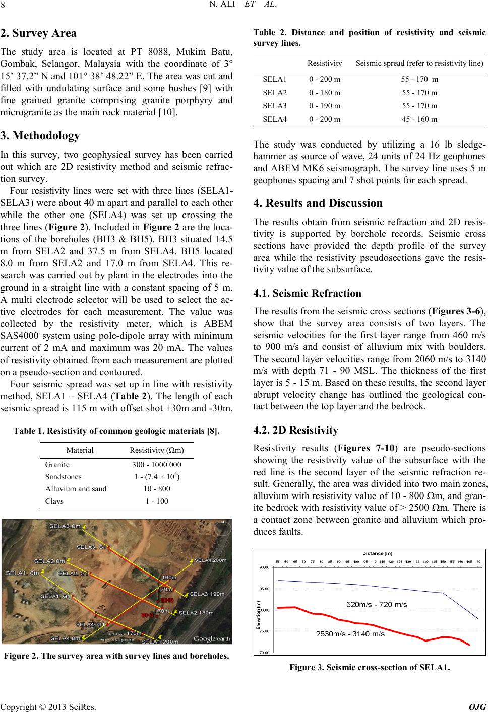 N. ALI ET AL. Copyright © 2013 SciRes. OJG 8 2. Survey Area The study area is located at PT 8088, Mukim Batu, Gombak, Selangor, Malaysia with the coordinate of 3° 15’ 37.2” N and 101° 38’ 48.22” E. The area was cut and filled with undulating surface and some bushes [9] with fine grained granite comprising granite porphyry and microgranite as the main rock material [10]. 3. Methodology In this survey, two geophysical survey has been carried out which are 2D resistivity method and seismic refrac- tion survey. Four resistivity lines were set with three lines (SELA1- SELA3) were about 40 m apart and parallel to each other while the other one (SELA4) was set up crossing the three lines (Figure 2). Inc luded in Figure 2 are the loca- tions of the boreholes (BH3 & BH5). BH3 situated 14.5 m from SELA2 and 37.5 m from SELA4. BH5 located 8.0 m from SELA2 and 17.0 m from SELA4. This re- search was carried out by plant in the electrodes into the ground in a straight line with a constant spacing of 5 m. A multi electrode selector will be used to select the ac- tive electrodes for each measurement. The value was collected by the resistivity meter, which is ABEM SAS4000 system using pole-dipole array with minimum current of 2 mA and maximum was 20 mA. The values of resistivity obtained from each measurement are plotted on a pseudo-section and contoured. Four seismic spread was set up in line with resistivity method, SELA1 – SELA4 (Table 2). The length of each seismic spread is 115 m with offset shot +30m and -30m. Table 1. Resistivity of common geologic materials [8]. Material Resistivity (Ωm) Granite 300 - 1000 000 Sandstones 1 - (7.4 × 10⁸) Alluvium and sand 10 - 800 Cla ys 1 - 100 Figure 2. The survey are a with sur vey lines and boreh ol es. Table 2. Distance and position of resistivity and seismic survey lines. Resistivity Seism ic spread (refer to resi stivity line) SELA1 0 - 200 m 55 - 170 m SELA2 0 - 180 m 55 - 170 m SELA3 0 - 190 m 55 - 170 m SELA4 0 - 200 m 45 - 160 m The study was conducted by utilizing a 16 lb sledge- hamme r as sour ce of wave , 24 units o f 24 H z geopho nes and ABEM M K6 se ismogr aph. The s urve y line uses 5 m geophones spacing and 7 shot points for each spread. 4. Results and Discussion The results obtain from seismic refraction and 2D resis- tivity is supported by borehole records. Seismic cross sections have provided the depth profile of the survey area while the resistivity pseudosections gave the resis- tivity va lue of the subsurface. 4.1. Seismic Refraction The results from the se i smic cro s s sectio ns (Figures 3-6), show that the survey area consists of two layers. The seismic velocities for the first layer range from 460 m/s to 900 m/s and consist of alluvium mix with boulders. The second layer velocitie s range from 2060 m/s to 3140 m/s with depth 71 - 90 MSL. The thickness of the first layer is 5 - 15 m. Based o n these results, the se co nd laye r abrupt velocity change has outlined the geological con- tact between the top layer and the bedrock. 4.2. 2D Resistivity Resistivity results (Figures 7-10) are pseudo-sections showing the resistivity value of the subsurface with the red line is the second layer of the seismic refraction re- sult. Generally, the area was divided into two main zones, alluvium with resi sti vi t y val ue o f 10 - 800 Ωm, and gra n- ite bedro ck with resi stivity value o f > 2500 Ωm. There is a contact zone between granite and alluvium which pro- duce s faults. Figure 3. Seismic cross-s ection of SELA1. 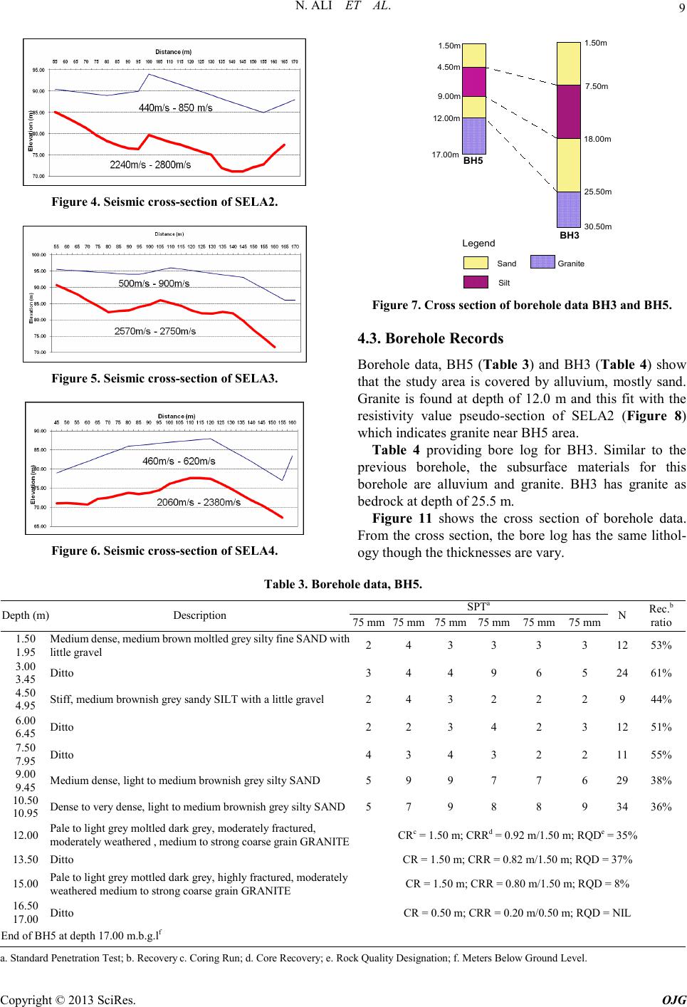 N. ALI ET AL. Copyright © 2013 SciRes. OJG 9 Figure 4. Seismic cross-s ection of SELA2. Figure 5. Seismic cross-s ection of SELA3. Figure 6. Seismic cross-s ection of SELA4. Legend Sand Silt Granite 1.50m 4.50m 9.00m 12.00m 17.00m BH5 1.50m 7.50m 18.00m 25.50m 30.50m BH3 Figure 7. Cross section of borehol e data BH3 and BH5. 4.3. Borehole Records Borehole data, BH5 (Table 3) and BH3 (Table 4) show that the study area is covered by alluvium, mostly sand. Granite is found at depth of 12.0 m and this fit with the resistivity value pseudo-section of SELA2 (Figure 8) which indicates granite near BH5 ar ea. Table 4 providing bore log for BH3. Similar to the previous borehole, the subsurface materials for this borehole are alluvium and granite. BH3 has granite as bedrock at depth of 25.5 m. Figure 11 shows the cross section of borehole data. From the cross section, the bore log has the same lithol- ogy thou gh the thicknesses are var y. Table 3. Bor e hole data, BH5 . Depth (m) Description SPTa N Rec.b ratio 75 mm 75 mm 75 mm 75 mm 75 mm 75 mm 1.50 1.95 Medi um de nse , m e dium br ow n mo ltl ed g re y si lty fine S A ND w ith little gravel 2 4 3 3 3 3 12 53% 3.00 3.45 Ditto 3 4 4 9 6 5 24 61% 4.50 4.95 Stiff, medium brownish grey sandy SILT with a little gravel 2 4 3 2 2 2 9 44% 6.00 6.45 Ditto 2 2 3 4 2 3 12 51% 7.50 7.95 Ditto 4 3 4 3 2 2 11 55% 9.00 9.45 Medium dense, light to medium brownish grey silty SAND 5 9 9 7 7 6 29 38% 10.50 10.95 Dense to very dense, light to medium brownish grey silty SAND 5 7 9 8 8 9 34 36% 12.00 Pale to light grey moltled dark grey, moderately fractured, moderately weathered , medium to strong coarse grain GRANITE CRc = 1.50 m; CRRd = 0.92 m/1.50 m; RQDe = 35% 13.50 Ditto CR = 1.50 m; CRR = 0.82 m/1. 50 m; RQD = 37% 15.00 Pale to light grey mott led dark grey, hi ghly fractured, moderately weathered medium to strong coarse grain GRANITE CR = 1.50 m; CRR = 0.80 m/1.50 m; RQD = 8% 16.50 17.00 Ditto CR = 0.50 m; CRR = 0.20 m/0.50 m; RQD = NIL End of B H5 at depth 17.00 m.b. g.lf a. Standard Penetration Test; b. Recovery c. Corin g Run; d. Core R ec overy; e. Rock Quality Designation; f. Meters Below Ground Level. 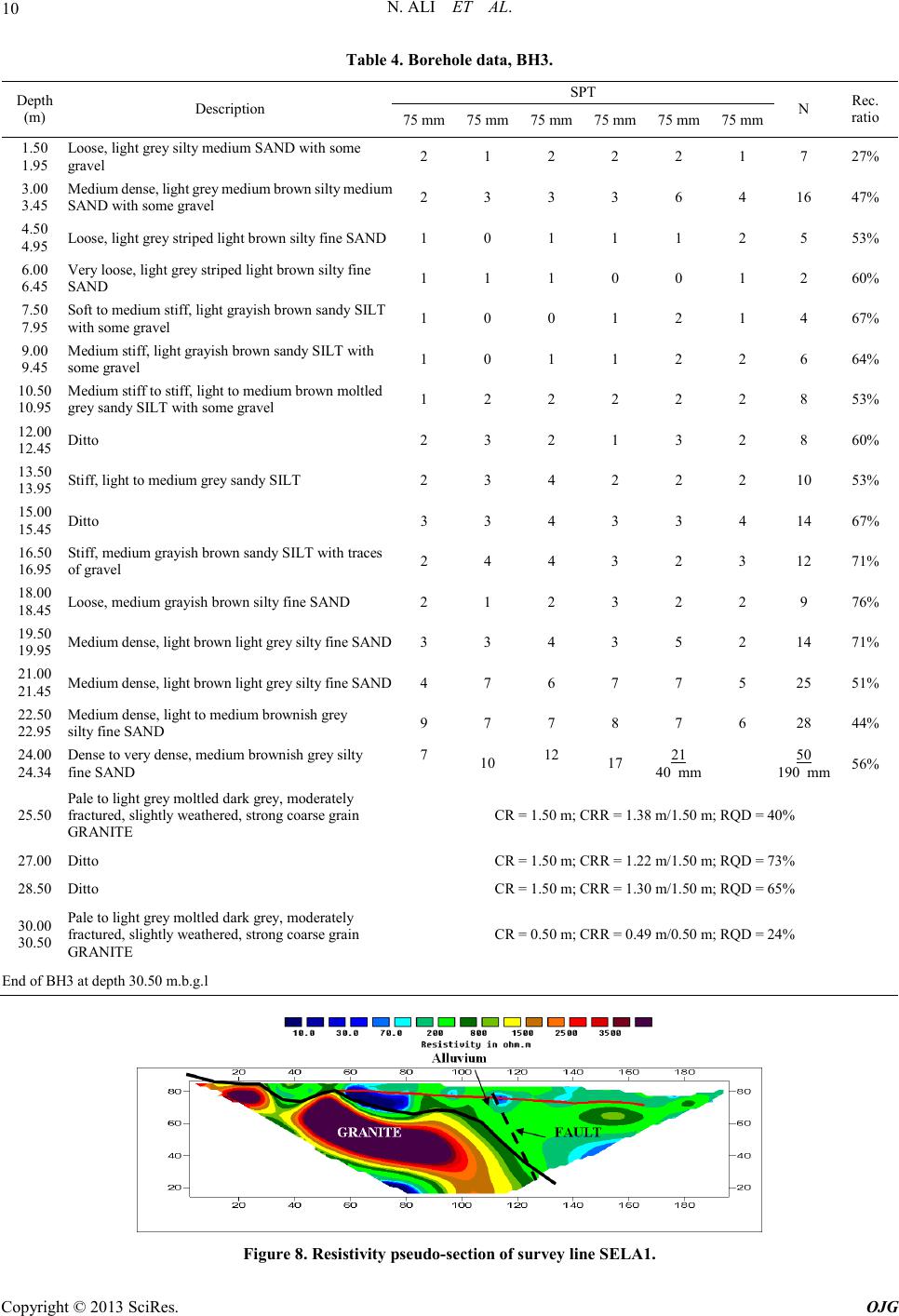 N. ALI ET AL. Copyright © 2013 SciRes. OJG 10 Table 4. Bor e hole data, BH3 . Depth (m) Description SPT N Rec. ratio 75 mm 75 mm 75 mm 75 mm 75 mm 75 mm 1.50 1.95 Loose, light grey silty medium SAND with some gravel 2 1 2 2 2 1 7 27% 3.00 3.45 Medi um de nse, l ig ht g rey medium bro w n silty me dium SAND with s om e gravel 2 3 3 3 6 4 16 47% 4.50 4.95 Loose, light gr ey striped light brown silty fine SAND 1 0 1 1 1 2 5 53% 6.00 6.45 Very loose, light grey striped light brown silty fine SAND 1 1 1 0 0 1 2 60% 7.50 7.95 Soft to medium st iff, light grayish brown sandy S ILT with s om e gravel 1 0 0 1 2 1 4 67% 9.00 9.45 Medium stiff, light grayish brown sandy SILT with some gravel 1 0 1 1 2 2 6 64% 10.50 10.95 Medium stiff to stiff, light to medium brown moltled grey sandy SILT with some gravel 1 2 2 2 2 2 8 53% 12.00 12.45 Ditto 2 3 2 1 3 2 8 60% 13.50 13.95 Stiff, light to medium grey sandy SILT 2 3 4 2 2 2 10 53% 15.00 15.45 Ditto 3 3 4 3 3 4 14 67% 16.50 16.95 Stiff, medium grayish brown sandy SILT with traces of gravel 2 4 4 3 2 3 12 71% 18.00 18.45 Loose, medium grayish brown silty fine SAND 2 1 2 3 2 2 9 76% 19.50 19.95 Medi um dens e , l ight br ow n l ight g r e y sil ty f ine SA ND 3 3 4 3 5 2 14 71% 21.00 21.45 Medi um dens e , l ight br ow n l ight g r e y sil ty f ine SA ND 4 7 6 7 7 5 25 51% 22.50 22.95 Medium dense , light to medium brownish grey silty fine SAND 9 7 7 8 7 6 28 44% 24.00 24.34 Dense to very dense, medium brownish grey silty fine S AND 7 10 12 17 21 40 mm 56% 50 190 mm 25.50 Pale t o l igh t grey moltl ed d ark grey, moderately fractur ed, sligh tly weather ed, stro ng coarse grain GRANIT E CR = 1.50 m; CRR = 1.38 m/1.50 m; RQD = 40% 27.00 Ditto CR = 1.50 m; CRR = 1.22 m/1.50 m; RQD = 73% 28.50 Ditto CR = 1.50 m; CRR = 1.30 m/1.50 m; RQD = 65% 30.00 30.50 Pale to li g ht g r ey molt led dark grey, m o derately fractur ed, sligh tly weather ed, stro ng coarse grain GRANIT E CR = 0.50 m; CRR = 0.49 m/0.50 m; RQD = 24% End of B H3 at depth 30.50 m.b. g.l Figure 8. Resist i vit y pseudo-section of survey line SELA1. 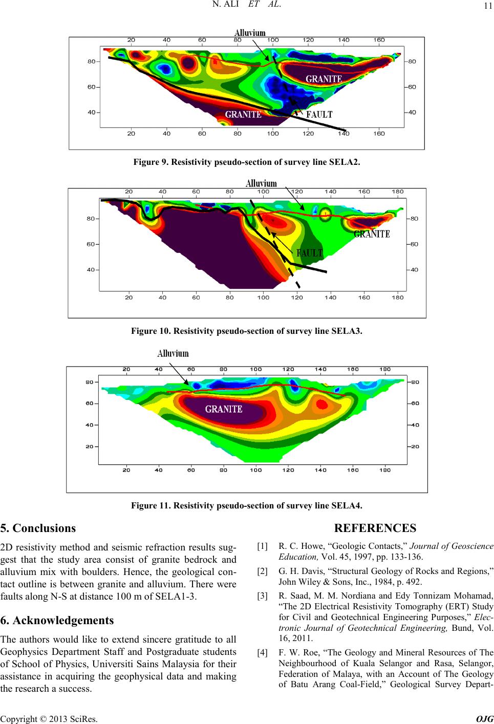 N. ALI ET AL. Copyright © 2013 SciRes. OJG 11 Figure 9. Resist i vit y pseudo-section of survey line SELA2. Figure 10. Resisti vity pseudo-section of s urvey line SELA3. Figure 11. Resistivity pseudo-section of su rvey line SEL A 4. 5. Conclusions 2D resistivity method and seismic refraction results sug- gest that the study area consist of granite bedrock and alluvium mix with boulders. Hence, the geological con- tact outline is between granite and alluvium. There were faults along N -S at distance 100 m of SELA1-3. 6. Acknowledgements The authors would like to extend sincere gratitude to all Geophysics Department Staff and Postgraduate students of School of Physics, Universiti Sains Malaysia for their assistance in acquiring the geophysical data and making the research a success. REFERENCES [1] R. C. Ho we, “Geologic Co ntacts,” Journal of Geoscience Education, Vol. 45, 199 7, pp. 133-136. [2] G. H. Davis, “Structural Geology of Rocks and Regions,” John Wiley & Sons, Inc., 1984, p. 492. [3] R. Saad, M. M. Nordiana and Edy Tonnizam Mohamad, “The 2D Electrical Resistivity Tomography (ERT) Study for Civil and Geotechnical Engineering Purposes,” Elec- tronic Journal of Geotechnical Engineering, Bund, Vol. 16, 2011 . [4] F. W. Roe, “The Geology and Mineral Resources of The Neighbourhood of Kuala Selangor and Rasa, Selangor, Federation of Malaya, with an Account of The Geology of Batu Arang Coal-Field,” Geological Survey Depart- 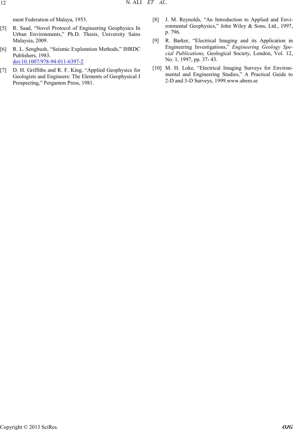 N. ALI ET AL. Copyright © 2013 SciRes. OJG 12 ment Federation of Malaya, 1953. [5] R. Saad, “Novel Protocol of Engineering Geophysics In Urban Environments,” Ph.D. Thesis, University Sains Malaysia, 2009. [6] R. L. Sengbush, “Seismic Exploration Methods,” IHRDC Publishers, 1983. doi:10.1007/978-94-011-6397-2 [7] D. H. Griffiths and R. F. King, “Applied Geophysics for Geologists and Engineers: The Elements of Geophysical J Prospecting,” Pergam on Pres s , 1981. [8] J. M. Reynolds, “An Introduction to Applied and Envi- ronmental Geophysics,” John Wiley & Sons, Ltd., 1997, p. 796. [9] R. Barker, “Electrical Imaging and its Application in Engineering Investigations,” Engineering Geology Spe- cial Publications, Geological Society, London, Vol. 12, No. 1, 1997, pp. 37- 43. [10] M. H. Loke, “Electrical Imaging Surveys for Environ- mental and Engineering Studies,” A Practical Guide to 2-D an d 3-D Su rveys, 1999.www.abem.se |