

Paper Menu >>
Journal Menu >>
 Energy and Power Engineering, 2013, 5, 429-433 doi:10.4236/epe.2013.54B083 Published Online July 2013 (http://www.scirp.org/journal/epe) Small Signal Stability Analysis for a DFIG-Based Offshore W ind Farms Collected Thr ough VSC-HVDC Transmission System Kai Liao, Zhengyou He, Bin Sun, Yong Jia School of Electrical Engineering, Southwest Jiaotong University, Chengdu, China Email: [email protected] Received April, 2013 ABSTRACT This paper modeled a doubly fed induction generator (DFIG) - based offshore wind farm integrated through a voltage source converter –based high voltage direct current (VSC-HVDC) transmission system, which is collected with infin ite bus for small signal stability analysis. The control system of HVDC system is considered for the stability analysis. The impact of the VSC control parameters on the network stability is studied. The lineared dynamic model is employed to do small signal stability analysis by th e eigenvalue analysis. The locus of th e eigenvalue, which is corresponding to the oscillation model is studied. Time domain si mulations conducted in Matlab/Simulink are used to validate the small sig- nal stability analysis. Keywords: DFIG; Offshore Wind Farm; VSC-HVDC; Small Signal Stability 1. Introduction Because the advantages in speed control, reduced flicker, and four-quadrant active and reactive power capabilities, are primarily achieved via control of a rotor side con- verter. Many large offshore wind farms based on DFIG (Doubly fed induction generator) have been planned around the world wide [1, 2]. The High-voltage dc (HVDC) transmission is emerging as the prospective technology to address the challenges associated with the integration of future offshore wind power [3]. In [4] and [5], a VSC transmission system was used to connect a 6-MWwind farm to the grid. VSC transmission systems were also proposed in [6], for transmitting off- shore wind power equipped fixed speed generators to the grid. However, many large wind farms under develop- ment will employ DFIG-based wind turbines whose op- eration and response to net-work disturbances are sig- nificantly different from other types of generators. In [7], line commutated HVDC systems were used to connect a large DFIG-based offshore wind farm into the grid. In [li xue] described the use of VSC-HVDC transmission sys- tem technology for connecting large DFIG-based wind farms over long distance. New control strategies for normal and grid fault conditions are proposed. To obtain smooth operation, the wind farm side VSC is controlled as an infinite voltage source that automatically absorbs power generated by the wind farm and maintains a stable local ac network. The dynamic behavior of the doubly fed induction ge- nerator (DFIG) has been investigated in many papers. The majority of these studies are based on time-domain simulations to show the impact on power syste m dynam- ics [8,9], the performance of decoupled control and maximum power tracking, the response to grid distur- bances, the control methods to make the DFIG behave like a synchronous generator [10-13], etc. Time-domain studies offer a direct appreciation of the dynamic behav- ior in terms of visual clarity. However, the time domain simulation can’t observe all oscillation modals [14 ]. In [15], a model suitable for small-signal stability analysis and control design of multi-terminal dc networks is presented. A generic test network that combines con- ventional synchronous and offshore wind generation connected to shore via a dc network is used to illustrate the design of enhanced voltage source converter (VSC) controllers. The impact of VSC control parameters on network stability is discussed and the overall network dynamic performance assessed in the event of small and large pert urbations . In this paper, the grid-connected DFIG via VSC-HVDC system is studied. The single-machine infinite-bus (SMIB) approach is followed. The paper is organized as follows. In Section II, the mathematical model is ob- served. In Section III, modal analysis method and the eigenvalue locus under different controller parameters is Copyright © 2013 SciRes. EPE 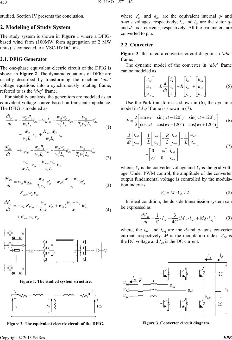 K. LIAO ET AL. 430 studied. Sectio n IV p rese nt s the conclusion. 2. Modeling of Study System The study system is shown in Figure 1 where a DFIG- based wind farm (100MW form aggregation of 2 MW units) is connected to a VSC-HVDC link. 2.1. DFIG Generator The one-phase equivalent electric circuit of the DFIG is shown in Figure 2. The dynamic equations of DFIG are usually described by transforming the machine ‘abc’ voltage equations into a synchronously rotating frame, referred to as the ‘d-q’ frame. For stability analysis, the generato rs are modeled as an equivalent voltage source based on transient impedance. The DFIG is modeled as 122 qs elel rel qsel dsqsds ss ss rss elmrr el qs qr ss ss di wRww w iwi ee dtw LwL TwL wKw vv wL wL (1) 122 dselel rel el qsdsdsqs ss ss rss elmrr el ds dr ss ss diw Rw ww wi iee dtw LwL TwL wKw vv wL wL (2) 2() qs els r el dsqselds rs s mrrel dr de www wRie we dtTww Kwv (3) 2() dselr s el dsdselqs rs s mrrel qr deww w wRiewe dtT ww Kwv (4) Figure 1. The studied system structure. Figure 2. The equivalent electric circuit of the DFIG. where ds e and ds e are the equivalent internal q- and d-axis voltages, respectively; ids and iqs are the stator q- and d- axis currents, respectively. All the parameters are converted to p.u. 2.2. Converter Figure 3 illustrated a converter circuit diagram in ‘abc’ frame. The dynamic model of the converter in ‘abc’ frame can be modeled as caaasa cbbbsb cccc sc uii d uLiRiu dt uii u u (5) Use the Park transform as shown in (6), the dynamic model in ‘d-q’ frame is shown in (7). sinsin(120 )sin(120 ) 2 3coscos(120 )cos(120 ) wt wtwt Pwt wtwt (6) 11 0 0 mdcd mdsd mqcq mqsq md mq iviu dR iviu dtL L L i i (7) where, Vc is the converter voltage and Vs is the grid volt- age. Under PWM control, the amplitude of the converter output fundamental voltage is controlled by the modula- tion index as /2 cdc VMV (8) In ideal condition, the dc side transmission syste m can be expressed as 13 () 4 dc dcd mdmq dV I Mi Mqi dt CC (9) where, the imd and imq are the d-and q- axis converter current, respectively. M is the modulation index. Vdc is the DC voltage and Idc is the DC current. dl I dc I 2C 2C d u s a u s b u s c u ca u cb u cc u m I R L Figure 3. Converter circuit diagram. Copyright © 2013 SciRes. EPE 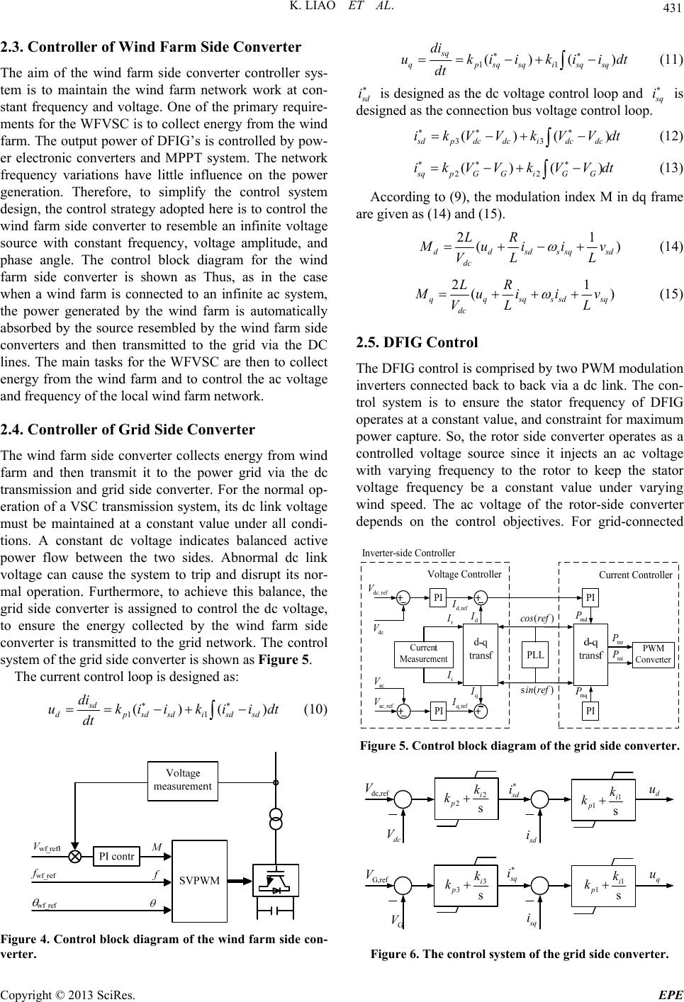 K. LIAO ET AL. 431 2.3. Controller of Wind Farm Side Converter The aim of the wind farm side converter controller sys- tem is to maintain the wind farm network work at con- stant frequency and voltage. One of the primary require- ments for the WFVSC is to collect energy from the wind farm. The output power of DFIG’s is contro lled by pow- er electronic converters and MPPT system. The network frequency variations have little influence on the power generation. Therefore, to simplify the control system design, the control strategy adopted here is to control the wind farm side converter to resemble an infinite voltage source with constant frequency, voltage amplitude, and phase angle. The control block diagram for the wind farm side converter is shown as Thus, as in the case when a wind farm is connected to an infinite ac system, the power generated by the wind farm is automatically absorbed by the source resembled by the wind farm side converters and then transmitted to the grid via the DC lines. The main tasks for the WFVSC are then to collect energy from the wind farm and to control the ac voltage and frequency of the local wind farm network. 2.4. Controller of Grid Side Converter The wind farm side converter collects energy from wind farm and then transmit it to the power grid via the dc transmission and grid side converter. For the normal op- eration of a VSC transmission system, its dc link voltage must be maintained at a constant value under all condi- tions. A constant dc voltage indicates balanced active power flow between the two sides. Abnormal dc link voltage can cause the system to trip and disrupt its nor- mal operation. Furthermore, to achieve this balance, the grid side converter is assigned to control the dc voltage, to ensure the energy collected by the wind farm side converter is transmitted to the grid network. The control system of the grid side conv erter is shown as Figure 5. The current control loop is designed as: 11 ()() sd dpsd sdisd sd di ukiikii dt dt (10) Figure 4. Control block diagr am of the wind farm side con- verter. 11 ()() sq qp sqsqisqsq di ukiikii dt dt (11) s d i is designed as the dc voltage control loop and s q i is designed as the connection bus voltage control loop. 33 ()( sdpdc dcidc dc ikVVkVVd )t t (12) 22 ()() sqpGGiGG ikVVkVVd (13) According to (9), the modulation index M in dq frame are give n as (14) and (15). 21 () ddsdssq dc LR sd M ui iv VL L (14) 21 () qqsqssd dc LR sq M ui i v VL L (15) 2.5. DFIG Control The DFIG control is comprised by two PWM modulation inverters connected back to back via a dc link. The con- trol system is to ensure the stator frequency of DFIG operates at a constant value, and constraint for maximum power capture. So, the rotor side converter operates as a controlled voltage source since it injects an ac voltage with varying frequency to the rotor to keep the stator voltage frequency be a constant value under varying wind speed. The ac voltage of the rotor-side converter depends on the control objectives. For grid-connected - dc ref V PI - dref I dc V - ac ref V PI - qref I ac V r I i I PLL ()cos ref s( )in ref d I q I md P mq P PI PI mr P mi P Inverter-side Controller Current Controller Voltage Controller Figure 5. Control block diagram of the grid side converter. dc,ref V 2 2s i p k k s d i dc V d u G,ref V q u G V 3 3 s i p k k 1 1 s i p k k 1 1 s i p k k s d i s q i s q i Figure 6. The control system of the grid side converter. Copyright © 2013 SciRes. EPE 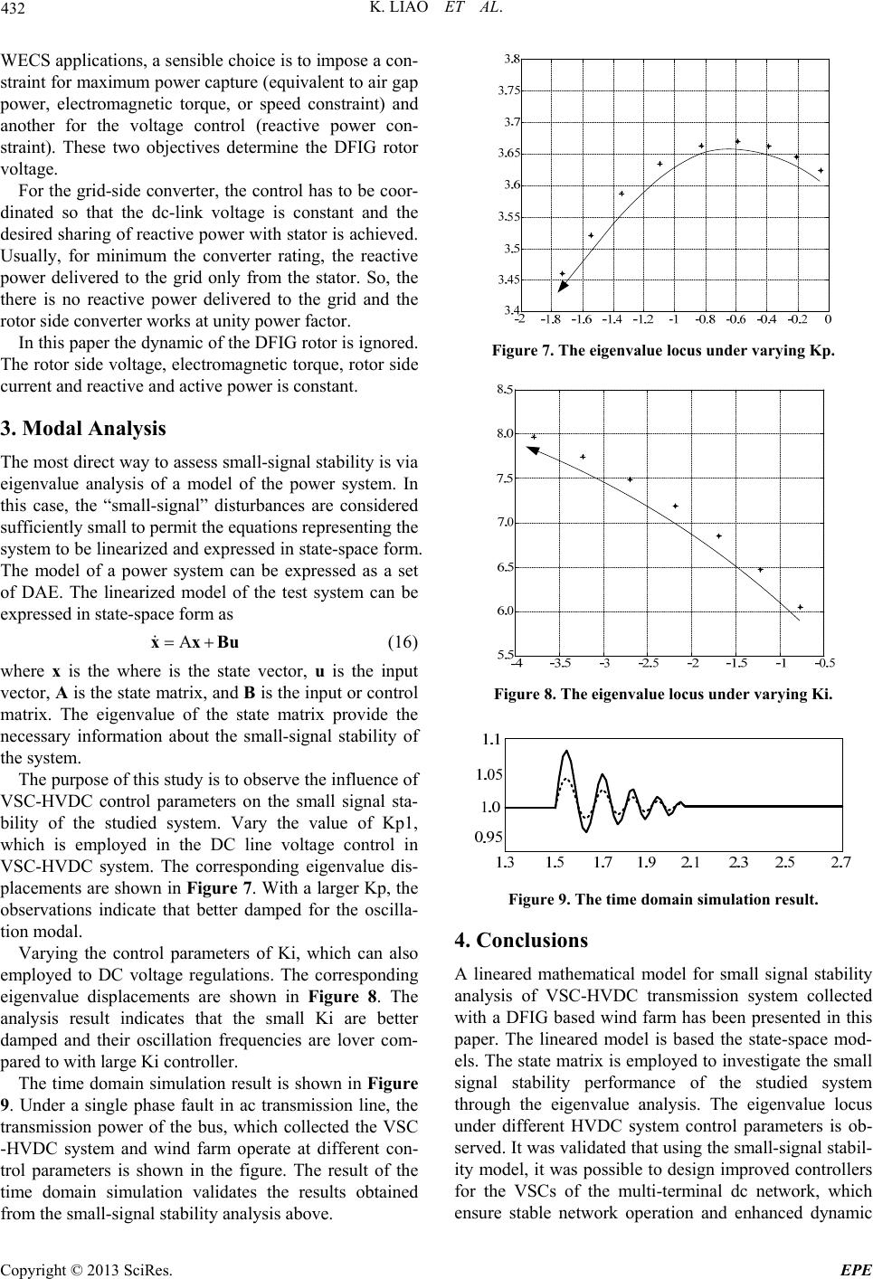 K. LIAO ET AL. 432 WECS applications, a sensible choice is to impose a con- straint for maximum power capture (equivalent to air gap power, electromagnetic torque, or speed constraint) and another for the voltage control (reactive power con- straint). These two objectives determine the DFIG rotor voltage. For the grid-side converter, the control has to be coor- dinated so that the dc-link voltage is constant and the desired sharing of reactive power with stator is achieved. Usually, for minimum the converter rating, the reactive power delivered to the grid only from the stator. So, the there is no reactive power delivered to the grid and the rotor side converter works at unity power factor. In this paper the dynamic of the DFIG rotor is ignored. The rotor side voltage, electromagnetic torque, rotor side current and reactive and active power is constant. 3. Modal Analysis The most direct way to assess small-signal stability is via eigenvalue analysis of a model of the power system. In this case, the “small-signal” disturbances are considered sufficiently small to permit the equations representing the system to be linearized and expressed in state-space form. The model of a power system can be expressed as a set of DAE. The linearized model of the test system can be expressed in state-space form as xxB u (16) where x is the where is the state vector, u is the input vector, A is the state matrix, and B is the input or control matrix. The eigenvalue of the state matrix provide the necessary information about the small-signal stability of the system. The purpose of th is study is to observe the influence of VSC-HVDC control parameters on the small signal sta- bility of the studied system. Vary the value of Kp1, which is employed in the DC line voltage control in VSC-HVDC system. The corresponding eigenvalue dis- placements are shown in Figure 7. With a larger Kp, the observations indicate that better damped for the oscilla- tion modal. Varying the control parameters of Ki, which can also employed to DC voltage regulations. The corresponding eigenvalue displacements are shown in Figure 8. The analysis result indicates that the small Ki are better damped and their oscillation frequencies are lover com- pared to with large Ki controller. The time domain simulation result is shown in Figure 9. Under a single phase fault in ac transmission line, the transmission power of the bus, which collected the VSC -HVDC system and wind farm operate at different con- trol parameters is shown in the figure. The result of the time domain simulation validates the results obtained from the small-signal stability analysis above. Figure 7. The eigenvalue locus under varying Kp. Figure 8. The eigenvalue locus under varying Ki. Figure 9. The time domain simulation result. 4. Conclusions A lineared mathematical model for small signal stability analysis of VSC-HVDC transmission system collected with a DFIG based wind farm has been presented in this paper. The lineared model is based the state-space mod- els. The state matrix is employed to investigate the small signal stability performance of the studied system through the eigenvalue analysis. The eigenvalue locus under different HVDC system control parameters is ob- served. It was validated that using the small-signal stabil- ity model, it was possible to design improved controllers for the VSCs of the multi-terminal dc network, which ensure stable network operation and enhanced dynamic Copyright © 2013 SciRes. EPE  K. LIAO ET AL. Copyright © 2013 SciRes. EPE 433 performance. The time domain simulation also validated the analysis results. REFERENCES [1] R. Pena, J. C. Clare and G. M. Asher, “Double Fed In- duction Generator using Back-to-back PWMconverter and its Application to Variable Speed Wind Energy Gen- eration,” Proceedings Institution Electric Engineering, Electric Power Applications, Vol. 143, No. 3, 1996, pp. 231-241. doi:10.1049/ip-epa:19960288 [2] T. Ackermann, “Transmission Systems for Offshore Wind Farms,” IEEE Power Engineering Review, Vol. 22, No. 12, 2002, pp. 23-27. doi:10.1109/MPER.2002.1098040 [3] W. Lu and B. T. Ooi, “Optimal Acquisition and Aggrega- tion of Offshore Wind Power by Multiterminal Volt- age-source HVDC,” IEEE Transactions Power Delivery, Vol. 18, No. 1, 2003, pp. 201-206. doi:10.1109/TPWRD.2002.803826 [4] K. H. Sobrink, P. L. Sorensen, P. Christensen, N. San- dersen, K. Eriksson, and P. Holmberg, “DC Feeder for Connection of a Wind Farm,” In Proceedings Cigre Symp., Malaysia, 1999. [5] X. I. Koutiva, T. D. Vrionis, N. A. Vovos, and G. B. Giannakopoulos, “Optimal Integration of an Offshore Wind Farm to a Weak Grid,” IEEE Transactions Power Delivery, Vol. 21, No. 2, 2006, pp. 987-994. doi:10.1109/TPWRD.2005.859275 [6] D. Xiang, L. Ran, J. R. Bumby, P. Tavner, and S. Yang, “Coordinated Control of an HVDC Link and Doubly Fed Induction Generators in a Large Offshore Wind Farm,” IEEE Transactions Power Delivery, Vol. 21, No. 1, 2006, pp.463-471.doi:10.1109/TPWRD.2005.858785 [7] L. Xu, L. Z. Yao, Christian Sasse. “Grid Integration of Large DFIG-based Wind Farms using VSC Transmis- sion,” IEEE Transactions Power System, Vol. 22, No. 3, pp 2007, 976-984. doi:10.1109/TPWRS.2007.901306 [8] J. G. Slootweg, “Wind Power Modelling and Impact on Power Systems Dynamics,” Ph.D. Dissertation, Delft Univ. Technology, Delft, The Netherlands, 2003. [9] V. Akhmatov, “Analysis of Dynamic Behaviour of Elec- tric Power Systems with Large Amount of Wind Power,” Ph.D. dissertation, Technology University Denmark, Lyngby, Denmark, 2003. [10] D. Alvira, J. Arevalo, C. Bermudez, R. Granadino, A. Granda, C. Pincella, G.P. Stigliano, and R. Vailati, “Fea- sibility Studies of the HVDC Submarine Interconnection between the Spanish Peninsula and the Balearic Island of Mallorca,” Presented at the 41th CIGREGen. Session, Paris, France, 2006, Paper B4-104. doi:10.1109/TEC.2004.832078 [11] M. V. A. Nunes, J. A. P. Lopes, H. H. Zurn, U. H. Bez- erra, and R. G. Almeida, “Influence of the Variable-speed wind Generators in Transient Stability Margin of the Conventional Generators Integrated in Electrical Grids,” IEEE Transctions Energy Conversion, Vol. 19, No. 4, 2004, pp. 692-701. doi:10.1109/TPWRS.2005.857275 [12] F. M. Hughes, O. Anaya-Lara, N. Jenkins, and G. Strbac, “Control of DFIG-based Wind Generation for Power Network Support,” IEEE Transactions Power System, Vol. 20, No. 4, 2005, pp. 1958-1966. [13] R. S. Pena, “Vector Control Strategies for a Doubly-fed induction Generator Driven by a Wind Turbine,” Ph.D. Dissertation, University Nottingham, Nottingham, U.K., 1996. [14] F. Mei and B. Pal, “Modal Analysis of Grid-connected doubly-fed Induction Generators,” IEEE Transactions Energy Conversions, Vol. 22, No. 3, 2007, pp. 728-736. doi:10.1109/TEC.2006.881080 [15] G. O. Kalcon, G. P. Adam, Olimpo Anaya-Lara, Stephen Lo, and Kjetil Uhlen. “Small-Signal Stabil- ity Analysis of Multi-Terminal VSC-Based DC Transmission Systems,” IEEE Transactions Power System, Vol. 27, No. 4, 2012, pp.1818-1830. doi:10.1109/TPWRS.2012.2190531 |