

Paper Menu >>
Journal Menu >>
 Energy and Power Engineering, 2013, 5, 418-422 doi:10.4236/epe.2013.54B081 Published Online July 2013 (http://www.scirp.org/journal/epe) Small-Signal Stability Analysis of Wind Power System Based on DFIG Bin Sun, Zhengyou He, Yong Jia, Kai Liao School of Electrical Engineering, Southwest Jiaotong University, Chengdu, China Email: [email protected] Received April, 2013 ABSTRACT This paper focuses on the small-signal stability of power syste m integrated with DFIG-based wind farm. The model of DFIG for small-signal stability analysis has built; the 3-generator 9-bus WECC test system is modified to investigate the impacts of large scale integration of wind power on power system small-signal stab ility. Different oscillatory modes are obtained with their eigenvalue, frequency and damping ratio, the results from eigenvalue analysis are presented to demonstrate the small-signal stability of power system is enhanced with the increasing output of the wind farm. Keywords: Small-Signal Stability; DFIG; Wind Power; Power System; Wind Farm 1. Introduction As of the end of 2011, the installed capacity of wind power in China has reached 62.36 GW [1], the planning and construction of large scale wind farm will be the inevitable trend of the development of wind power in China. Wind power has obvious characteristics of ran- domness, volatility and intermittent, this development affects the small-signal stability of the traditional power system, so it is significant to study the impacts of large scale integration of wind power on power system small-signal stability. In [2], an aggregated wind farm model with DFIG based wind turbine for small-signal stability study is proposed to deal with the situation that the wind turbin es operate receiving different incoming wind speeds. In [3], the 10-generator 39-bus New England test system is ap- plied to assess the effect of the large scale wind farm on power system small-signal stability. In [4], the effect of wind power on the oscillations is investigated by gradu- ally replacing the power generated by the synchronous generators in the system by power from either constant or variable speed wind turbines, while observing the movement of the eigenvalues through the complex plane. The aim of this paper is to study the small-signal sta- bility of wind power system based on DFIG. This paper is structured as follows, with DFIG model in section II, and section III describe the modified 3-generator 9-bus WECC system applied in the simulation and analysis. The small-signal stability analysis of DFIG based wind farm is described in section IV, with discussions and conclusions presented in section V. 2. Modeling of DFIG There are mainly three kinds of wind turbine widely used nowadays: the constant speed wind turbine with squirrel cage induction generator, the variable speed wind turbine with doubly fed induction generator (DFIG) and the di- rect drive synchronous generator. The main differences between the three schemes are the generating system and the way in which the aerodyna mic efficiency of the rotor is limited during wind speed variations [5, 6]. As a mat- ter of fact, each of the wind generating systems has its own advantages and disadvantages. Almost all newer larger wind generating system being produced are vari- able speed systems based on DFIGs, so DFIG based wind farm is the main object in this study. As is well known, the rotor terminals of a DFIG are fed with a symmetrical three-phase voltage of variable frequency and amplitude fed through a voltage source converter usually equipped with IGBT based power elec- tronic circuitry [7]. The basic topolog y of DFIG is shown in Figure 1. 2.1. Turbine and Drive Train The mechanical power input to the wind turbine is con- sidered as constant, so the pitch angle do not change during the period of study. In this paper, the two-mass drive train model [8] is considered and the dynamics can be expressed by the following d ifferential equations [9]: 1 2 r s he g dTT dt H (1) t bt r d dt (2) Copyright © 2013 SciRes. EPE 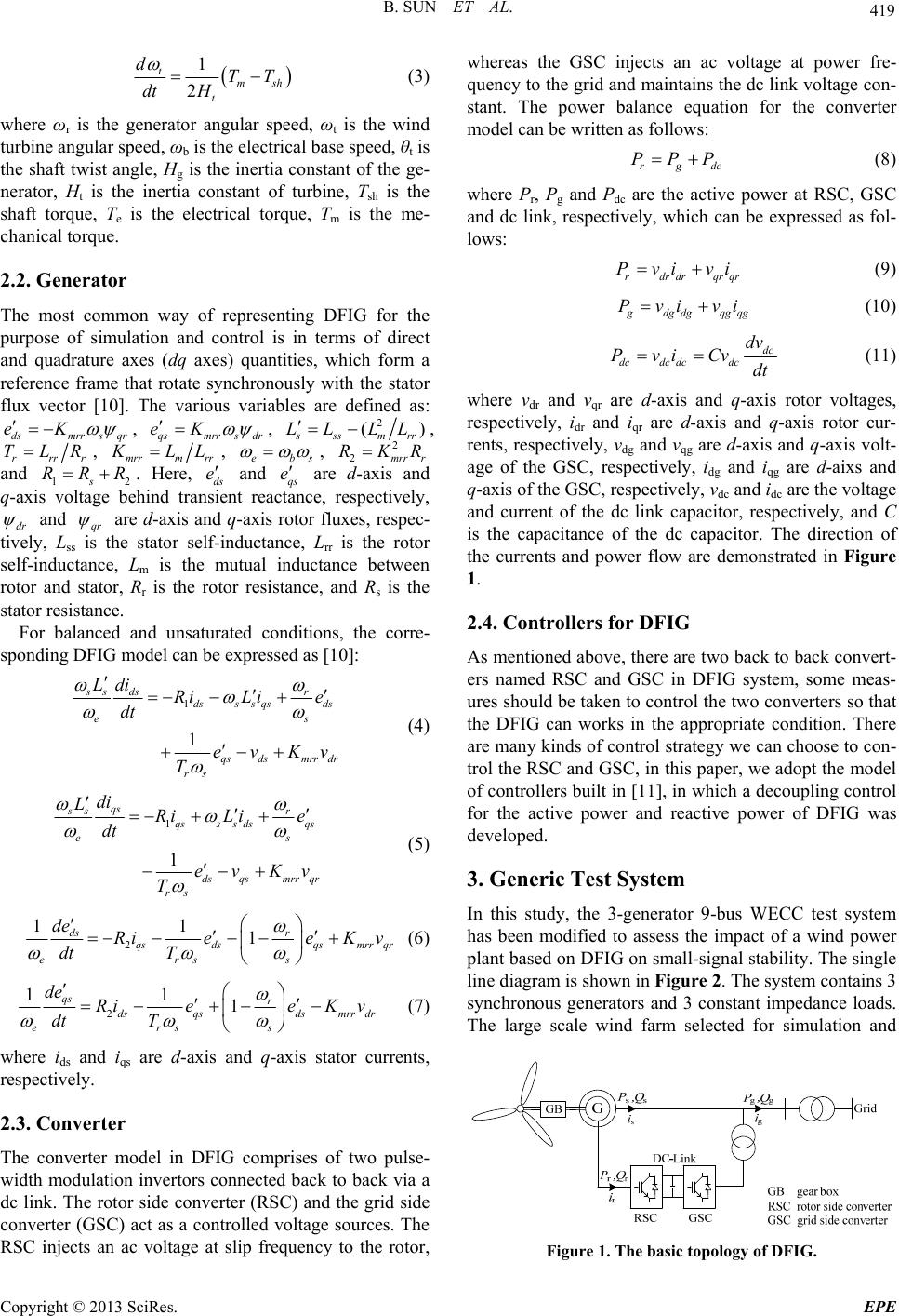 B. SUN ET AL. 419 1 2 t msh t dTT dt H (3) where ωr is the generator angular speed, ωt is the wind turbine angular speed, ωb is the electrical base speed, θt is the shaft twist angle, Hg is the inertia constant of the ge- nerator, Ht is the inertia constant of turbine, Tsh is the shaft torque, Te is the electrical torque, Tm is the me- chanical torque. 2.2. Generator The most common way of representing DFIG for the purpose of simulation and control is in terms of direct and quadrature axes (dq axes) quantities, which form a reference frame that rotate synchronously with the stator flux vector [10]. The various variables are defined as: dsmrr s qr eK , qsmrr s dr eK , 2 () s ssm rr LL LL , rrrr TLR, mrrm rr K LL, e sb e, and 12s. Here, ds and qs are d-axis and q-axis voltage behind transient reactance, respectively, dr 2 2mrr r RKR RRRe and qr are d-axis and q-axis rotor fluxes, respec- tively, Lss is the stator self-inductance, Lrr is the rotor self-inductance, Lm is the mutual inductance between rotor and stator, Rr is the rotor resistance, and Rs is the stator resistance. For balanced and unsaturated conditions, the corre- sponding DFIG model can be expressed as [10]: 1 1 ss dsr dsssqsds e qsdsmrr dr rs Ldi Ri Lie dt evKv T s (4) 1 1 qs ss r qsss dsqs e dsqsmrr qr rs di LRi Lie dt evKv T s (5) 2 11 1 ds r qsdsqsmrr qr erss de RieeK v dt T (6) 2 11 1 qs r dsqsdsmrr dr erss de RieeK v dt T (7) where ids and iqs are d-axis and q-axis stator currents, respectively. 2.3. Converter The converter model in DFIG comprises of two pulse- width modulation invertors connected back to back via a dc link. The rotor side converter (RSC) and the grid side converter (GSC) act as a controlled voltage sources. The RSC injects an ac voltage at slip frequency to the rotor, whereas the GSC injects an ac voltage at power fre- quency to the gr id and maintains the dc link vo ltage con- stant. The power balance equation for the converter model can be written as follows: rgd PPP c (8) where Pr, Pg and Pdc are the active power at RSC, GSC and dc link, respectively, which can be expressed as fol- lows: rdrdrqrq Pvivi r (9) g dg dgqg qg Pvi vi (10) dc dcdc dcdc dv Pvi Cv dt (11) where vdr and vqr are d-axis and q-axis rotor voltages, respectively, idr and iqr are d-axis and q-axis rotor cur- rents, respectively, vdg and vqg are d-axis and q-axis volt- age of the GSC, respectively, idg and iqg are d-aixs and q-axis of the GSC, respectively, vdc and idc are the voltage and current of the dc link capacitor, respectively, and C is the capacitance of the dc capacitor. The direction of the currents and power flow are demonstrated in Figure 1. 2.4. Controllers for DFIG As mentioned above, there are two back to back convert- ers named RSC and GSC in DFIG system, some meas- ures should be taken to control the tw o converters so that the DFIG can works in the appropriate condition. There are many kinds of control strategy we can choose to con- trol the RSC and GSC, in this paper, we adopt the model of controllers built in [1 1], in which a decou pling control for the active power and reactive power of DFIG was developed. 3. Generic Test System In this study, the 3-generator 9-bus WECC test system has been modified to assess the impact of a wind power plant based on DFIG on small-signal stab ility. The single line diagram is shown in Figure 2. The system contains 3 synchronous generators and 3 constant impedance loads. The large scale wind farm selected for simulation and Figure 1. The basic topology of DFIG. Copyright © 2013 SciRes. EPE 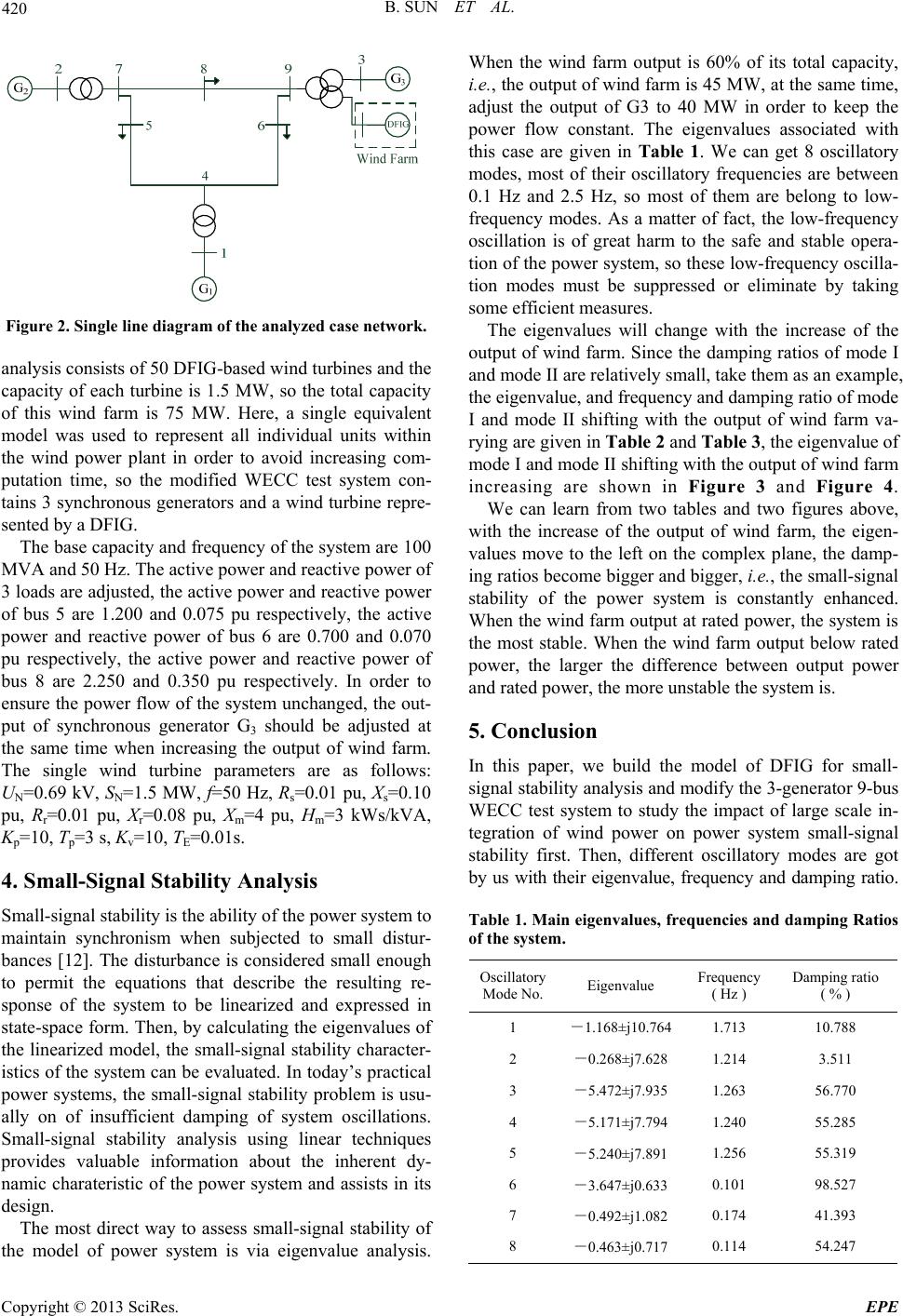 B. SUN ET AL. 420 Figure 2. Single line diagram of the analyzed case network. analysis consists of 50 DFIG-based wind turbines and the capacity of each turbine is 1.5 MW, so the total capacity of this wind farm is 75 MW. Here, a single equivalent model was used to represent all individual units within the wind power plant in order to avoid increasing com- putation time, so the modified WECC test system con- tains 3 synchronous generators and a wind turbine repre- sented by a DFIG. The base capacity and frequency of the system are 100 MVA and 50 Hz. The active power and reactive power of 3 loads are adjusted, the active power and reactive power of bus 5 are 1.200 and 0.075 pu respectively, the active power and reactive power of bus 6 are 0.700 and 0.070 pu respectively, the active power and reactive power of bus 8 are 2.250 and 0.350 pu respectively. In order to ensure the power flow of the system unchanged, the out- put of synchronous generator G3 should be adjusted at the same time when increasing the output of wind farm. The single wind turbine parameters are as follows: UN=0.69 kV, SN=1.5 MW, f=50 Hz, Rs=0.01 pu, Xs=0.10 pu, Rr=0.01 pu, Xr=0.08 pu, Xm=4 pu, Hm=3 kWs/kVA, Kp=10, Tp=3 s, Kv=10, TE=0.01s. 4. Small-Signal Stability Analysis Small-signal stability is the ability of the power system to maintain synchronism when subjected to small distur- bances [12]. The disturbance is considered small enough to permit the equations that describe the resulting re- sponse of the system to be linearized and expressed in state-space form. Then, by calculating the eigenvalues of the linearized model, the small-signal stability character- istics of the system can be evaluated. In today’s practical power systems, the small-signal stability problem is usu- ally on of insufficient damping of system oscillations. Small-signal stability analysis using linear techniques provides valuable information about the inherent dy- namic charateristic of the power system and assists in its design. The most direct way to assess small-signal stability of the model of power system is via eigenvalue analysis. When the wind farm output is 60% of its total capacity, i.e., the output of wind farm is 45 MW, at the same time, adjust the output of G3 to 40 MW in order to keep the power flow constant. The eigenvalues associated with this case are given in Table 1. We can get 8 oscillatory modes, most of their oscillatory frequencies are between 0.1 Hz and 2.5 Hz, so most of them are belong to low- frequency modes. As a matter of fact, the low-frequency oscillation is of great harm to the safe and stable opera- tion of the power system, so these low-frequency oscilla- tion modes must be suppressed or eliminate by taking some efficient measures. The eigenvalues will change with the increase of the output of wind farm. Since the damping ratios of mode I and mode II are relatively small, take them as an example, the eigenvalue, and frequency and damping ratio of mode I and mode II shifting with the output of wind farm va- rying are given in Table 2 and Table 3, the eigenvalue of mode I and mode II shifting with the output of wind farm increasing are shown in Figure 3 and Figure 4. We can learn from two tables and two figures above, with the increase of the output of wind farm, the eigen- values move to the left on the complex plane, the damp- ing ratios become bigger and bigger, i.e., the small-signal stability of the power system is constantly enhanced. When the wind far m output at rated power, the system is the most stable. When the wind farm output below rated power, the larger the difference between output power and rated power, the more unstable the system is. 5. Conclusion In this paper, we build the model of DFIG for small- signal stability an alysis and modify the 3-generator 9-bus WECC test system to study the impact of large scale in- tegration of wind power on power system small-signal stability first. Then, different oscillatory modes are got by us with their eigenvalue, frequency and damping ratio. Table 1. Main eigenvalues, frequenc ies and damping Ratios of the system. Oscillatory Mode No.Eigenvalue Frequency ( Hz ) Damping ratio ( % ) 1 -1.168±j10.764 1.713 10.788 2 -0.268±j7.628 1.214 3.511 3 -5.472±j7.935 1.263 56.770 4 -5.171±j7.794 1.240 55.285 5 -5.240±j7.891 1.256 55.319 6 -3.647±j0.633 0.101 98.527 7 -0.492±j1.082 0.174 41.393 8 -0.463±j0.717 0.114 54.247 Copyright © 2013 SciRes. EPE 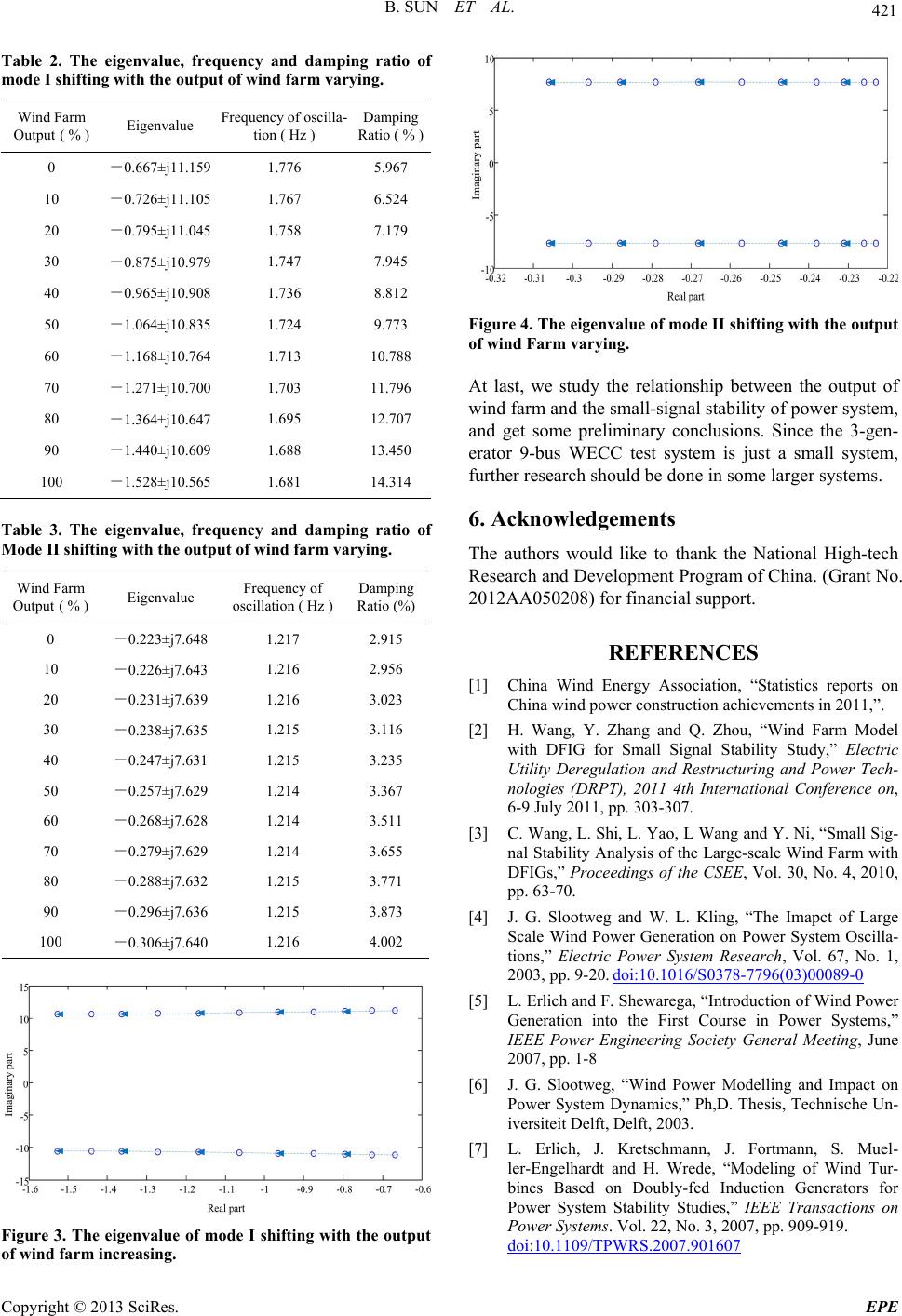 B. SUN ET AL. 421 Table 2. The eigenvalue, frequency and damping ratio of mode I shifting with the output of wind farm varying. Wind Farm Output ( % ) Eigenvalue Frequency of oscilla- tion ( Hz ) Damping Ratio ( % ) 0 -0.667±j11.159 1.776 5.967 10 -0.726±j11.105 1.767 6.524 20 -0.795±j11.045 1.758 7.179 30 -0.875±j10.979 1.747 7.945 40 -0.965±j10.908 1.736 8.812 50 -1.064±j10.835 1.724 9.773 60 -1.168±j10.764 1.713 10.788 70 -1.271±j10.700 1.703 11.796 80 -1.364±j10.647 1.695 12.707 90 -1.440±j10.609 1.688 13.450 100 -1.528±j10.565 1.681 14.314 Table 3. The eigenvalue, frequency and damping ratio of Mode II shifting with the output of wind farm varyi ng. Wind Farm Output ( % ) Eigenvalue Frequency of oscillation ( Hz ) Damping Ratio (%) 0 -0.223±j7.648 1.217 2.915 10 -0.226±j7.643 1.216 2.956 20 -0.231±j7.639 1.216 3.023 30 -0.238±j7.635 1.215 3.116 40 -0.247±j7.631 1.215 3.235 50 -0.257±j7.629 1.214 3.367 60 -0.268±j7.628 1.214 3.511 70 -0.279±j7.629 1.214 3.655 80 -0.288±j7.632 1.215 3.771 90 -0.296±j7.636 1.215 3.873 100 -0.306±j7.640 1.216 4.002 Figure 3. The eigenvalue of mode I shifting with the output of wind farm incre asing. Figure 4. The eigenvalue of mode II shifting with the output of wind Farm varying. At last, we study the relationship between the output of wind farm and the small-signal stability of power system, and get some preliminary conclusions. Since the 3-gen- erator 9-bus WECC test system is just a small system, further research should be done in some larger systems. 6. Acknowledgements The authors would like to thank the National High-tech Research and Development Program of China. (Grant No. 2012AA050208) for financial support. REFERENCES [1] China Wind Energy Association, “Statistics reports on China wind power construction achievements in 2011,”. [2] H. Wang, Y. Zhang and Q. Zhou, “Wind Farm Model with DFIG for Small Signal Stability Study,” Electric Utility Deregulation and Restructuring and Power Tech- nologies (DRPT), 2011 4th International Conference on, 6-9 July 2011, pp. 303-307. [3] C. Wang, L. Shi, L. Yao, L Wang and Y. Ni, “Sma ll Sig- nal Stability Analysis of the Large-scale Wind Farm with DFIGs,” Proceedings of the CSEE, Vol. 30, No. 4, 2010, pp. 63-70. [4] J. G. Slootweg and W. L. Kling, “The Imapct of Large Scale Wind Power Generation on Power System Oscilla- tions,” Electric Power System Research, Vol. 67, No. 1, 2003, pp. 9-20. doi:10.1016/S0378-7796(03)00089-0 [5] L. Erlich and F. Shewarega, “Introduction of Wind Power Generation into the First Course in Power Systems,” IEEE Power Engineering Society General Meeting, June 2007, pp. 1-8 [6] J. G. Slootweg, “Wind Power Modelling and Impact on Power System Dynamics,” Ph,D. Thesis, Technische Un- iversiteit Delft, Delft, 2003. [7] L. Erlich, J. Kretschmann, J. Fortmann, S. Muel- ler-Engelhardt and H. Wrede, “Modeling of Wind Tur- bines Based on Doubly-fed Induction Generators for Power System Stability Studies,” IEEE Transactions on Power Systems. Vol. 22, No. 3, 2007, pp. 909-919. doi:10.1109/TPWRS.2007.901607 Copyright © 2013 SciRes. EPE  B. SUN ET AL. Copyright © 2013 SciRes. EPE 422 [8] S. K. Salman and A. L. J. Teo, “Windmill Modeling Con- sideration and Factors Infulencing the Stability of a Grid-connected Wind Power Based Embedded Genera- tor,” IEEE Transactions on Power Systems. Vol. 18, No. 2, 2003, pp. 793-802. doi:10.1109/TPWRS.2003.811180 [9] F. Mei and B. C. Pal, “Modal Analysis of Grid Connected Doubly Fed Induction Generator,” IEEE Transactions on Energy Conversion. Vol. 22, No. 3, 2007, pp. 728-736. doi:10.1109/TEC.2006.881080 [10] F. Mei and B. C. Pal, “Modeling and Small Signal Analy- sis of a Grid Connected Doubly Fed Induction Genera- tor,” IEEE Power Engineering Society General Meeting, San Francisco, 12-16 June 2005,pp. 2101-2108. [11] F. Wu, X. Zhang, K. Godfrey and P. Ju, “Modeling and Control of Wind Turbine with Doubly Fed Induction Ge- nerator” 2006 IEEE PES Power System Conference and Exposition, 29 October-1 November 2006, pp. 1404-1409. doi:10.1109/PSCE.2006.296507 [12] P. Kundur, “Power System Stability and Control” McGraw-Hill, Inc., New York, 1994. |