

Paper Menu >>
Journal Menu >>
 Journal of Signal and Information Processing, 2013, 4, 132-137 doi:10.4236/jsip.2013.43B023 Published Online August 2013 (http://www.scirp.org/journal/jsip) A Transient Enhancement Method for Two-Stage Helicopter Gearbox Fault Diagnosis Based on ALE Xiange Tian1, Tie Wang2, Zhi Chen2, Fengshou Gu1, Andrew Ball1 1Centre for Efficiency and Performance Engineering, University of Huddersfield, Huddersfield, UK; 2Department of Vehicle Engi- neering, Taiyuan University of Technology Taiyuan, Shanxi Province, China. Email: [email protected], [email protected] Received April, 2013. ABSTRACT Periodical impulse component is one of typical fault characteristics in vibration signals from rotating machinery. How- ever, this component is very small in the early stage of the fault and masked by various noises such as gear meshing components modulated by shaft frequency, which make it difficult to extract accurately for fault detection. The adaptive line enhancer (ALE) is an effective technique for separating sinusoidals from broad-band components of an input signal for detecting the presence of sinusoids in white noise. In this paper, ALE is explored to suppress the periodical gear meshing frequencies and enhance the fault feature impulses for more accurate fault diagnosis. The results obtained from simulated and experimental vibration signals of a two stage helical gearbox prove that the ALE method is very effective in reducing the periodical gear meshing noise and making the impulses in vibration very clear in the time-frequency analysis. The results show a clear difference between the baseline and 30% tooth damage of a helical gear which has not been detected successfully in author’s previous studies. Keywords: Adaptive Filter; Adaptive Line Enhancement; Transient Enhancement; Fault Diagnosis 1. Introduction Impulsive sound and vibration signals in machinery are often caused by component impacts which are commonly associated with component faults. It has long been rec- ognized that the presence of a fault is often indicated by the presence, or increase in, impulsive signal elements. However, it tends to be difficult to make objective meas- urements of impulsive signals because of the high levels of background noise. The detection of these impulsive signals is hampered by the presence of the signals asso- ciated with the normal running of the machine, with the consequence that the detection of the weak impulsive signals, which are especially associated with incipient faults, is difficult [1]. It is the ‘normal’ signals which form the background noise environment against which the detection of fault induced impulsive signals must be conducted. To improve the precision of fault diagnosis, it is valuable to enhance the impulsive signals by sup- pressing this background noise prior to further process- ing. De-noising and extraction of such faulty signals are very important for fault diagnostics, especially for early fault detection, in which the fault features are often very weak and embedded in noise. Therefore, it is necessary to enhance the data reliability and improve the accuracy of the signal analysis. After successful pre-processing the signal has an increased Signal to Noise Ratio (SNR), which makes it more amenable to one of a gamut of sig- nal processing tools which can be used to characterize the signal, including Auto-Regressive (AR) modeling, kurtosis evaluation, cepstrum analysis, time-frequency analysis and higher order spectra analysis [2]. The ALE was introduced in as a method of detecting a periodic signal in an incoherent background or con- versely of removing periodic interference from a broad-band signal of interest [3]. This technique can be used with any of the adaptive filters classified till now and uses a delay in the input signal to cancel out the un- necessary part in it and thus get the desired response. Naoto Sasaoka etc. applied ALE to reduce the sinusoidal noise in noise speech signal [4]. J. R. Mohammed etc. presented one noise reduction system based on two stag- es of operation with the first stage based on the ALE fil- ters and the second stage on NLMS (Normalized Least Mean Square) filter. The first stage reduces the sinusoi- dal noise from the input signal and the second stage re- duces the wideband noise [5]. S. K. Lee and P. R. White exploits two stage ALE filter structures in series to re- duce the level of background noise. The resulting en- hanced signals are analyzed in the time-frequency do- main to obtain simultaneous spectral and temporal in- Copyright © 2013 SciRes. JSIP 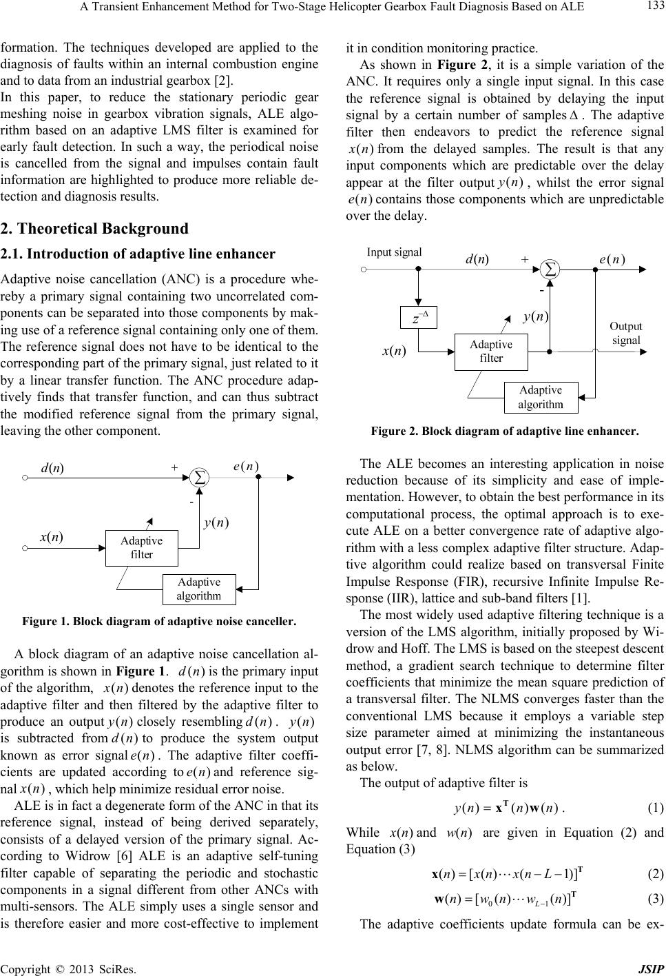 A Transient Enhancement Method for Two-Stage Helicopter Gearbox Fault Diagnosis Based on ALE 133 formation. The techniques developed are applied to the diagnosis of faults within an internal combustion engine and to data from an industrial gearbox [2]. In this paper, to reduce the stationary periodic gear meshing noise in gearbox vibration signals, ALE algo- rithm based on an adaptive LMS filter is examined for early fault detection. In such a way, the periodical noise is cancelled from the signal and impulses contain fault information are highlighted to produce more reliable de- tection and diagnosis results. 2. Theoretical Background 2.1. Introduction of adaptive line enhancer Adaptive noise cancellation (ANC) is a procedure whe- reby a primary signal containing two uncorrelated com- ponents can be separated into those components by mak- ing use of a reference signal containing only one of them. The reference signal does not have to be identical to the corresponding part of the primary signal, just related to it by a linear transfer function. The ANC procedure adap- tively finds that transfer function, and can thus subtract the modified reference signal from the primary signal, leaving the other component. )(ny )(nd )(ne )(nx Figure 1. Block diagram of adaptive noise canceller. A block diagram of an adaptive noise cancellation al- gorithm is shown in Figure 1. is the primary inpu t of the algorithm, ()dn () x n ()yn (dn denotes the reference input to the adaptive filter and then filtered by the adaptive filter to produce an outputclosely resembling. is subtracted from to produce the system output known as error signal. The adaptive filter coeffi- cients are updated according toand reference sig- nal ()dn ()yn ) (en)(en) () x n, which help minimize residual error noise. ALE is in fact a degenerate form of the ANC in that its reference signal, instead of being derived separately, consists of a delayed version of the primary signal. Ac- cording to Widrow [6] ALE is an adaptive self-tuning filter capable of separating the periodic and stochastic components in a signal different from other ANCs with multi-sensors. The ALE simply uses a single sensor and is therefore easier and more cost-effective to implement it in condition monitoring practice. As shown in Figure 2, it is a simple variation of the ANC. It requires only a single input signal. In this case the reference signal is obtained by delaying the input signal by a certain number of samples. The adaptive filter then endeavors to predict the reference signal () x n ()en from the delayed samples. The result is that any input components which are predictable over the delay appear at the filter output, whilst the error signal contains those components which are unpredictable over the delay. ()yn )(ny )(nd )(ne )(nx z Figure 2. Block diagram of adaptive line enhancer. The ALE becomes an interesting application in noise reduction because of its simplicity and ease of imple- mentation. However, to obtain th e best perfor mance in its computational process, the optimal approach is to exe- cute ALE on a better convergence rate of adaptive algo- rithm with a less complex adaptive filter structure. Adap- tive algorithm could realize based on transversal Finite Impulse Response (FIR), recursive Infinite Impulse Re- sponse (IIR), lattice and sub-band filters [1]. The most widely used adaptive filtering technique is a version of the LMS algorithm, initially proposed by Wi- drow and Hoff. The LMS is based on the steepest descent method, a gradient search technique to determine filter coefficients that minimize the mean square prediction of a transversal filter. The NLMS converges faster than the conventional LMS because it employs a variable step size parameter aimed at minimizing the instantaneous output error [7, 8]. NLMS algorithm can be summarized as below. The output of adaptive filter is ()() ()ynn nT xw . (1) While () x nand are given in Equation (2) and Equation (3) ()wn () [()(1)]nxnxnL Τ x Τ (2) 01 () [()()] L nwnwn w (3) The adaptive coefficients update formula can be ex- Copyright © 2013 SciRes. JSIP 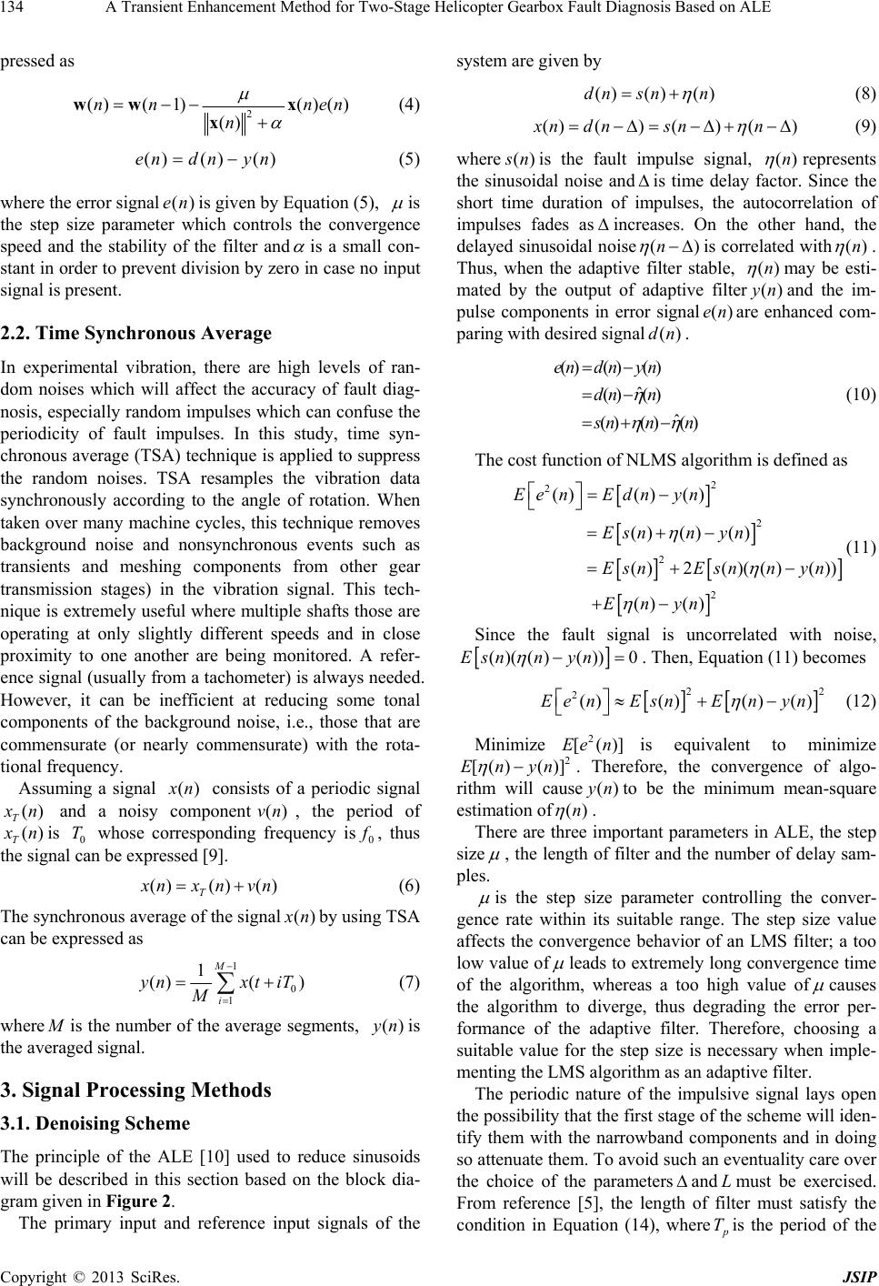 A Transient Enhancement Method for Two-Stage Helicopter Gearbox Fault Diagnosis Based on ALE 134 pressed as 2 ()( 1)()() () nn ne n ww x xn ()() ()endn yn (4) (5) where the error signalis given by Equation (5), ()en is the step size parameter which controls the convergence speed and the stability of the filter and is a small con- stant in order to prevent division by zero in case no input signal is present. 2.2. Time Synchronous Average In experimental vibration, there are high levels of ran- dom noises which will affect the accuracy of fault diag- nosis, especially random impulses which can confuse the periodicity of fault impulses. In this study, time syn- chronous aver age (TSA) technique is applied to supp ress the random noises. TSA resamples the vibration data synchronously according to the angle of rotation. When taken over many machine cycles, this technique removes background noise and nonsynchronous events such as transients and meshing components from other gear transmission stages) in the vibration signal. This tech- nique is extremely useful where multiple shafts those are operating at only slightly different speeds and in close proximity to one another are being monitored. A refer- ence signal (usually from a tachometer) is always needed. However, it can be inefficient at reducing some tonal components of the background noise, i.e., those that are commensurate (or nearly commensurate) with the rota- tional frequency. Assuming a signal () x n consists of a periodic signal () T x n () T and a noisy component, the period of ()vn x nis 0 whose corresponding frequency isT0 f , thus the signal can be expressed [9]. ()() () T x nxnvn (6) The synchronou s av er age of the signal() x nby using TSA can be expressed as 1 0 1 1 ()( ) M i y nxt M iT (7) where M is the number of the average segments, is the averaged signal. ()yn 3. Signal Processing Methods 3.1. Denoising Scheme The principle of the ALE [10] used to reduce sinusoids will be described in this section based on the block dia- gram given in Figure 2. The primary input and reference input signals of the system are given by () () ()dn snn (8) ()()()(xn dnsnn) ) (9) where ( s nis the fault impulse signal, ()n represents the sinusoidal noise and is time delay factor. Since the short time duration of impulses, the autocorrelation of impulses fades as increases. On the other hand, the delayed sinusoidal noise(n) is correlated with()n . Thus, when the adaptive filter stable, ()n may be esti- mated by the output of adaptive filterand the im- pulse components in error signalare enhanced com- paring with desired signal. ()yn ()en ()dn ()() () ˆ () () ˆ () () () endn yn dn n s nnn (10) The cost function of NLMS algorithm is defined as 2 2 () () () ()2()(() ()) () () Esnn yn EsnEsnnyn Enyn 2 2 2 ()() ()Ee nEdnyn (11) Since the fault signal is uncorrelated with noise, ()(()())0nnyn Es . Then, Equation (11) becomes 22 2()()() ()Ee nEsnEnyn 2 [()]Ee n (12) Minimize is equivalent to minimize . Therefore, the convergence of algo- rithm will causeto be the minimum mean-square estimation of 2 )]n()yn ()n [() (Eny . There are three important parameters in ALE, the step size , the length of filter and the number of delay sam- ples. is the step size parameter controlling the conver- gence rate within its suitable range. The step size value affects the convergence behavior of an LMS filter; a too low value of leads to extremely long convergence time of the algorithm, whereas a too high value of causes the algorithm to diverge, thus degrading the error per- formance of the adaptive filter. Therefore, choosing a suitable value for the step size is necessary when imple- menting the LMS algorithm as an adaptive filter. The periodic nature of the impulsive signal lays open the possibility that the first stage of the scheme will iden- tify them with the narrowband components and in doing so attenuate them. To avoid such an eventuality care over the choice of the parametersand must be exercised. From reference [5], the length of filter must satisfy the condition in Equation (14), where L p Tis the period of the Copyright © 2013 SciRes. JSIP 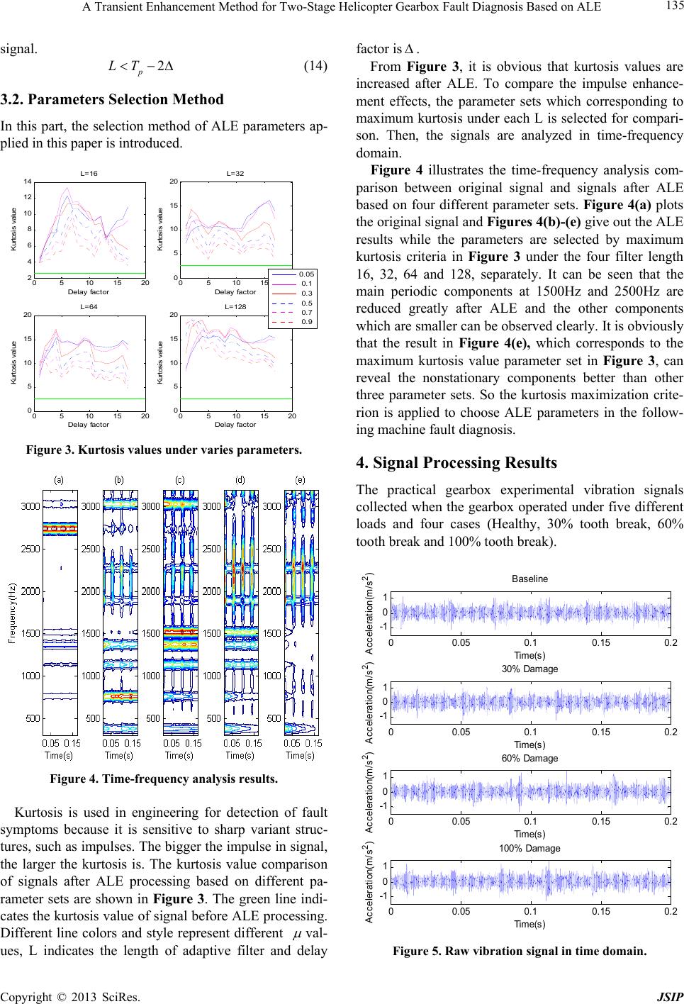 A Transient Enhancement Method for Two-Stage Helicopter Gearbox Fault Diagnosis Based on ALE 135 signal. 2 p LT (14) 3.2. Parameters Selection Method In this part, the selection method of ALE parameters ap- plied in this paper is introduced. 05 10 15 20 2 4 6 8 10 12 14 Delay factor Kurto s is v alue L=16 05 10 15 20 0 5 10 15 20 Delay factor Kurto s is v alue L=32 05 10 15 20 0 5 10 15 20 Delay factor Kurtosis v alue L=64 05 10 15 20 0 5 10 15 20 Delay factor Kurtosis v alue L=128 0.05 0.1 0.3 0.5 0.7 0.9 Figure 3. Kurtosis values under varies parameters. Figure 4. Time-frequency analysis results. Kurtosis is used in engineering for detection of fault symptoms because it is sensitive to sharp variant struc- tures, such as impulses. The bigger the impulse in signal, the larger the kurtosis is. The kurtosis value comparison of signals after ALE processing based on different pa- rameter sets are shown in Figure 3. The green line indi- cates the kurtosis value of signal before ALE processing. Different line colors and style represent different val- ues, L indicates the length of adaptive filter and delay factor is . From Figure 3, it is obvious that kurtosis values are increased after ALE. To compare the impulse enhance- ment effects, the parameter sets which corresponding to maximum kurtosis under each L is selected for compari- son. Then, the signals are analyzed in time-frequency domain. Figure 4 illustrates the time-frequency analysis com- parison between original signal and signals after ALE based on four different parameter sets. Figure 4(a) plots the original signal and Figures 4(b)-(e) give out the ALE results while the parameters are selected by maximum kurtosis criteria in Figure 3 under the four filter length 16, 32, 64 and 128, separately. It can be seen that the main periodic components at 1500Hz and 2500Hz are reduced greatly after ALE and the other components which are smaller can be observed clearly. It is obviously that the result in Figure 4(e), which corresponds to the maximum kurtosis value parameter set in Figure 3, can reveal the nonstationary components better than other three parameter sets. So the kurtosis maximization crite- rion is applied to choose ALE parameters in the follow- ing machine fault diagnosis. 4. Signal Processing Results The practical gearbox experimental vibration signals collected when the gearbox operated under five different loads and four cases (Healthy, 30% tooth break, 60% tooth break and 100% tooth break). 00.05 0.10.15 0.2 -1 0 1 Tim e(s) A cceleration(m /s 2 ) Baseline 00.05 0.10.15 0.2 -1 0 1 Tim e(s) Acceleration(m/s 2 ) 30% Damage 00.05 0.10.15 0.2 -1 0 1 Tim e(s) Acceleration(m/s 2 ) 60% Damage 00.05 0.10.15 0.2 -1 0 1 Tim e(s) Acceleration(m/s 2 ) 100% Damage Figure 5. Raw vibration signal in time domain. Copyright © 2013 SciRes. JSIP  A Transient Enhancement Method for Two-Stage Helicopter Gearbox Fault Diagnosis Based on ALE 136 00.05 0.10.15 0.2 -0. 5 0 0.5 Time(s) Acceleration(m/s2) Baseline 00.05 0.10.15 0.2 -0. 5 0 0.5 Time(s) Accel eration(m /s2) 30% Damage 00.05 0.10.15 0.2 -0. 5 0 0.5 Time(s) Acceleration(m/s2) 60% Damage 00.05 0.10.15 0.2 -0. 5 0 0.5 Time(s) Acceleration(m/s2) 100% Damage Figure 6. TSA vibration signal in time domain. Figure 5 gives out the raw vibration data for four cas- es under load 3, where the baseline is the healthy case. Figure 6 shows the TSA results of the vibration signals given out in Fig. 3 for five revolutions of the input shaft. It can be seen that the impulse components of the vibra- tion signals are highlighted for all the test conditions. TSA signals show much clearer indication of the 60% and 100% tooth damage compared with the baseline and 30% tooth damage. However the signals between the baseline and 30% tooth damage cannot be observed with noticeable differences. To evaluate the denoise effect of ALE algorithm, Fig- ure 7 and Figure 8 give out the time-frequency analysis results comparison , take the signal under the 4th load as example, signals under other loads have similar per- formance. As shown in Figure 8, there are several periodical modulation frequencies generated by rotation of machine and can be seen as background noise at about 1500Hz, 3000Hz and 4500Hz. The purpose of ALE is to remove these frequencies. The TSA signals also contain impulse components which are short duration and periodical con- tents for certain frequencies which are spread over the time direction. These components carry the fault infor- mation of gearbox tooth break damage. Figure 8 shows the results after the ALE processing. It can be seen that the modulation frequencies are reduced significantly. The results show that ALE is effective in reducing sinusoids and extract impulses from wide band periodical noises. For a detailed comparison, two common feature pa- rameters: root mean square (RMS) and kurtosis are cal- culated from the TSA vibration signals ALE errors sig- nals. As shown in Figure 9(a), RMS is not able to sepa- rate the four cases over different loads. Comparing with the baseline and 30% tooth damage, in Figure 9(b), the kurtosis values of 60% tooth damage and 100% tooth damage is clearly separated from the other two cases except the first load. However, the difference between the baseline and 30% tooth damage is not very obvious for fault separation. Figure 9(c) and Figure 9(d) illus- trate the RMS and kurtosis value comparison from the error signal which is the signal after ALE denoising processing. From the RMS value comparison of error signal, there are differences between all loads except the first and all four fault cases which gives out clear differ- ence compared with TSA signal. The kurtosis value of error signal is much higher than that of TSA signal, when means the proportion of impulses is enhanced. But the difference between kurtosis values of different fault cases is not so clearly as the RMS value of error signal. Figure 7. TSA vibration signals in time-frequency domain. Figure 8. Signals after ALE in time-frequency domain. Copyright © 2013 SciRes. JSIP  A Transient Enhancement Method for Two-Stage Helicopter Gearbox Fault Diagnosis Based on ALE Copyright © 2013 SciRes. JSIP 137 12345 0. 02 0. 03 0. 04 0. 05 0. 06 Load inde x RM S valu e (a) RMS of TSA Si gnal Baseline 30% Dam age 60% Dam age 100% Dam age 12345 2 4 6 8 10 12 Load inde x Kurtosis value (b) Kurt osis of TSA Si gnal 12345 0. 01 0. 02 0. 03 0. 04 0. 05 Load inde x RM S value (c ) RMS of E rror S i gnal 12345 0 10 20 30 40 Load inde x Kurtosis v alue (d) K urtosis o f Erro r S i gn al Figure 9. RMS and kurtosis value comparison of TSA and error signal (L = 20, mu = 0.075, Δ = 12). 1 2 3 45 0. 02 0. 03 0. 04 0. 05 0. 06 Load index RMS value (a) RMS of TSA Signal Baseline 30% Damage 60% Damage 100% Damage 12 34 5 2 4 6 8 10 12 Load index Kurtosis value (b) K urto si s of TSA Si g nal 1 2 3 45 0. 01 0. 02 0. 03 0. 04 0. 05 Load index RMS value (c) RM S of E rror Si gnal 12 34 5 0 5 10 15 20 Load index Kurtosis value (d) K urtosi s of E rro r S i gn al Figure 10. RMS and kurtosis value comparison of TSA and error signal (L = 32, mu = 0.0375, Δ = 60). Figure 10 illustrates the results obtained from another set of ALE parameters, the results for 30% tooth damage is worse, while for higher severity faults the results is better. 5. Conclusions In this study, ALE has been examined for the fault detec- tion and diagnosis of a two stage helical gearbox based on noisy vibration signals. TSA is used to suppress the random noise firstly and then ALE is to reduce the con- tinuous meshing components, which allows impulsive features shown by the time-frequency analysis represen- tations to be highlighted effectively. In this way, the in- cipient tooth damage fault can be detected clearly. REFERENCES [1] R. M. Ramli, A. O. A. Noor and S. A. Samad, “A Review of Adaptive Line Enhancers for Noise Cancellation,” Austral ian Jou rnal of Basi c and Appl ied Sci ences, Vol. 6, No. 6, 2012, pp. 337-352. [2] S. K. Lee and P. R. White, “The Enhancement of Impul- sive Noise and Vibration Signals for Fault Detection in Rotating and Reciprocating Machinery,” Journal of Sound and Vibration, Vol. 217, No. 3, 1998, pp. 485-505. doi:10.1006/jsvi.1998.1767 [3] J. R. Treichler, “Transient and Convergent Behaviour of the Adaptive Line Enhancer,” IEEE Trans. Acousr. Speech Signal Processing. Vol. ASSP-27, pp. 53- 62. [4] N. Sasaoka, K. Sumi, Y. Itoh and K. Fujii, “A New Noise Reduction System Based on ALE and Noise Reconstruc- tion Filter,” In proceeding of: International Symposium on Circuits and Systems, Kobe, 23-26 May 2005. [5] J. R. Mohammed, M. S. Shafi, S. Imtiaz etc. “An Effi- cient Adaptive Noise Cancellation Scheme Using ALE and NLMS Filters,” International Journal of Electrical and Computer Engineering, Vol. 2, No. 3, pp. 325-332. [6] B. Widrow, J. R. Glover Jr, J. M. McCool, J. Kaunitz, C. S. Williams, R. H. Hearn, J. R. Zeidler, D. Eugene, Jr. and R. C. Goodlin, “Adaptive Noise Cancelling: Princi- ples and Applications,” Proceedings of the IEEE, Vol. 63, No. 12, pp. 1692-1716. [7] S. Haykin, “Adaptive Filter Theory,” Prentice Hall, 2002. [8] S. R. Diniz, P., 2008. Adaptive Filtering: Algorithms and Practical Implementation, Springer. [9] W. T. Wu, J. Lin, S. B. Han and X. H. Ding, “Time do- main averaging based on fractional delay filter,” Me- chanical Systems and Signal Processing, Volume 23, No. 5, 2009, pp. 1447-1457. doi:10.1016/j.ymssp.2009.01.017 [10] J. R. Mohammed, “A New Simple Adaptive Noise Can- cellation Scheme Based on ALE and NLMS Filter,” An- nual Conf. Communication, Networks, Services Research, May 2007, pp. 245-254. |