

Paper Menu >>
Journal Menu >>
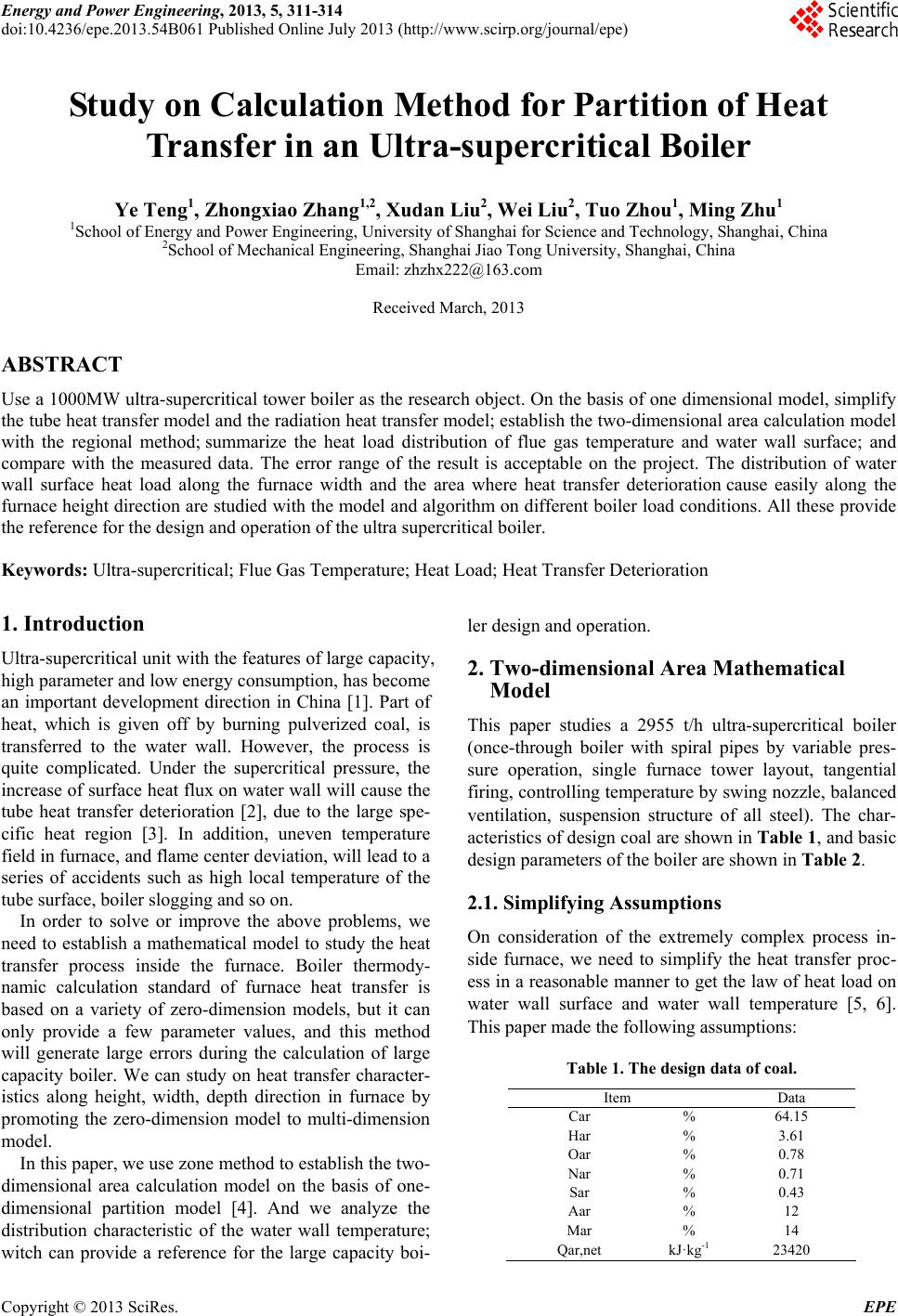 Energy and Power Engineering, 2013, 5, 311-314 doi:10.4236/epe.2013.54B061 Published Online July 2013 (http://www.scirp.org/journal/epe) Study on Calculation Method for P artition of Heat Transfer in an Ultra-supercritical Boiler Ye Teng1, Zhongxiao Zhang1,2, X u da n Liu2, Wei Liu2, Tuo Zhou1, Ming Zhu1 1School of Energy and Power Engineering, University of Shanghai for Science and Technology, Shanghai, China 2School of Mechanical Engineering, Shanghai Jiao Tong University, Shanghai, China Email: [email protected] Received March, 2013 ABSTRACT Use a 1000MW ultra-supercritical tower boiler as the research object. On the basis of one dimensional model, simplify the tube heat transfer model and the radiation heat transfer model; establish the two-dimensional area calculation model with the regional method; summarize the heat load distribution of flue gas temperature and water wall surface; and compare with the measured data. The error range of the result is acceptable on the project. The distribution of water wall surface heat load along the furnace width and the area where heat transfer deterioration cause easily along the furnace height direction are studied with the model and algorithm on different boiler load conditions. All these provide the reference for the design and operation of the ultra supercritical boiler. Keywords: Ultra-supercritical; Flue Gas Temperature; Heat Load; Heat Transfer Deterioration 1. Introduction Ultra-supercritical unit with the features of large capacity, high parameter and low energy consumption, has become an important development direction in China [1]. Part of heat, which is given off by burning pulverized coal, is transferred to the water wall. However, the process is quite complicated. Under the supercritical pressure, the increase of surface heat flux on water wall will cause the tube heat transfer deterioration [2], due to the large spe- cific heat region [3]. In addition, uneven temperature field in furnace, and flame center deviation, will lead to a series of accidents such as high local temperature of the tube surface, boiler slogging and so on. In order to solve or improve the above problems, we need to establish a mathematical model to study the heat transfer process inside the furnace. Boiler thermody- namic calculation standard of furnace heat transfer is based on a variety of zero-dimension models, but it can only provide a few parameter values, and this method will generate large errors during the calculation of large capacity boiler. We can study on heat transfer character- istics along height, width, depth direction in furnace by promoting the zero-dimension model to multi-dimension model. In this paper, we use zone method to establish th e two- dimensional area calculation model on the basis of one- dimensional partition model [4]. And we analyze the distribution characteristic of the water wall temperature; witch can provide a reference for the large capacity boi- ler design and operation. 2. Two-dimensional Area Mathematical Model This paper studies a 2955 t/h ultra-supercritical boiler (once-through boiler with spiral pipes by variable pres- sure operation, single furnace tower layout, tangential firing, controlling temperature by swing nozzle, balanced ventilation, suspension structure of all steel). The char- acteristics of design coal are shown in Table 1, and basic design parameters of the boiler are shown in Table 2. 2.1. Simplifying Assumptions On consideration of the extremely complex process in- side furnace, we need to simplify the heat transfer proc- ess in a reasonable manner to get the law of heat load on water wall surface and water wall temperature [5, 6]. This paper made the following assumptions: Table 1. The design data of coal. Item Data Car % 64.15 Har % 3.61 Oar % 0.78 Nar % 0.71 Sar % 0.43 Aar % 12 Mar % 14 Qar,net kJ·kg-1 23420 Copyright © 2013 SciRes. EPE 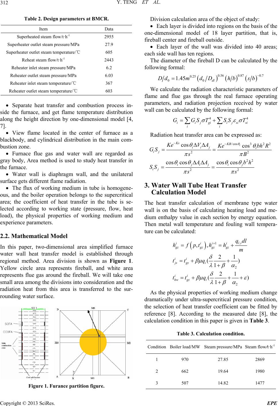 Y. TENG ET AL. 312 Table 2. Design parameters at BMCR. Item Data Superheated steam flow/t·h-1 2955 Superheater outlet steam pressure/MPa 27.9 Superheater outlet steam temperature/℃ 605 Reheat steam flow/t·h-1 2443 Reheater inlet steam pressure/MPa 6.2 Reheater outlet steam pressure/MPa 6.03 Reheater inlet steam temperature/℃ 367 Reheater outlet steam temperature/℃ 603 Separate heat transfer and combustion process in- side the furnace, and get flame temperature distribution along the height direction by one-dimensional model [4, 7]. View flame located in the center of furnace as a blackbody, and cylindrical distribution in the main com- bustion zone. Furnace flue gas and water wall are regarded as gray body, Area method is used to study heat transfer in the furnace. Water wall is diaphragm wall, and the unilateral surface gets different flame radiation. The flux of working medium in tube is homogene- ous, and the boiler operation belongs to the supercritical area; the coefficient of heat transfer in the tube is se- lected according to working state (pressure, flow, heat load), the physical properties of working medium and experience parameters. 2.2. Mathematical Model In this paper, two-dimensional area simplified furnace water wall heat transfer model is established through regional method. Area division is shown as Figure 1. Yellow circle area represents fireball, and white area represents flue gas around the fireball. We will take one small area among the divisions into consid eration an d the radiation heat from this area is transferred to the sur- rounding water surface. Figure 1. Furance partition figure. Division calculation area of the object of study: Each layer is divided into regions on the basis of the one-dimensional model of 18 layer partition, that is, fireball center and fireball outside. Each layer of the wall was divided into 40 areas; each side wall has ten regions. The diameter of the fireball D can be calculated by the following formal: 0.56 0.87 0.7 0.25 00 1.45 dl Ddmd Dhbsb We calculate the radiation characteristic parameters of flame and flue gas through the real furnace operating parameters, and radiation projection received by water wall can be calculated by the following formal: 44 iijgiijsi ii GGST SST si Radiation heat transfer area can be expressed as: /cos 32 22 22 22 cos cos cos coscos cos i Ks KB iij i ij ijij ij ij KeV A2 K eb GS sB AA bh SS ss hR 3. Water Wall Tube Heat Transfer Calculation Model The heat transfer calculation of membrane type water wall is on the basis of calculating heating load and me- dium enthalpy value in each section by energy equation. Then metal wall temperature and fouling wall tempera- ture can be calculated: , 1 2 2 ,, 21 () 1 21 () 1 li iiii gzgz gzgz ii js gzi ii hw gzi qdl hfpthh m tt q tt q As the physical properties of working medium change dramatically under ultra-supercritical pressure condition, the selection of heat transfer coefficient can be fitted by reference [8]. According to the measured date [8], the calculation condition in this paper is given in Table 3. Table 3. Calculation condition. ConditionBoiler load/MWSteam pressure/MPa Steam flow/t·h-1 1 970 27.85 2869 2 662 19.64 1980 3 507 14.82 1477 Copyright © 2013 SciRes. EPE 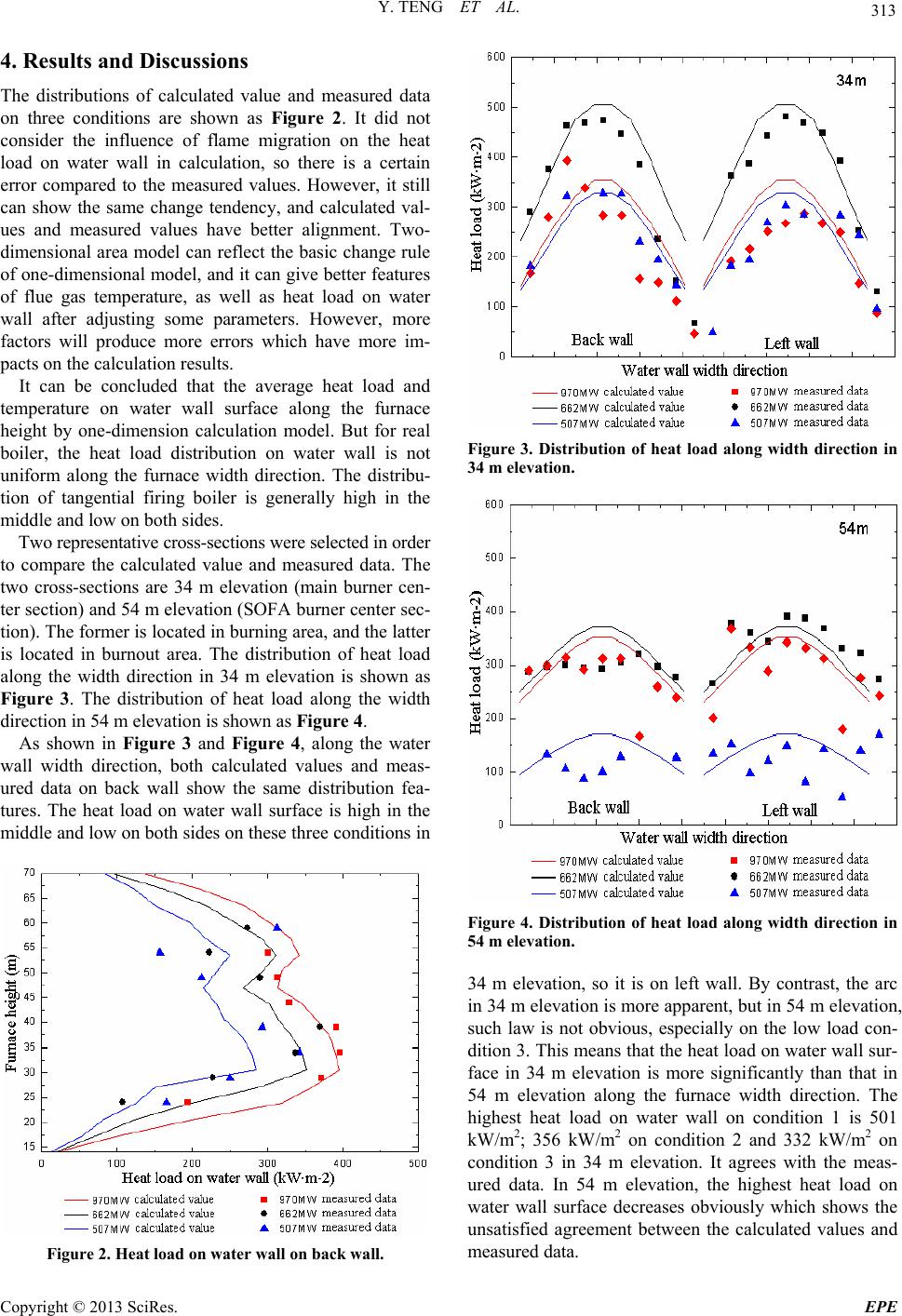 Y. TENG ET AL. 313 4. Results and Discussions The distributions of calculated value and measured data on three conditions are shown as Figure 2. It did not consider the influence of flame migration on the heat load on water wall in calculation, so there is a certain error compared to the measured values. However, it still can show the same change tendency, and calculated val- ues and measured values have better alignment. Two- dimensional area model can reflect the basic change rule of one-dimensional model, and it can give better features of flue gas temperature, as well as heat load on water wall after adjusting some parameters. However, more factors will produce more errors which have more im- pacts on the calculation results. It can be concluded that the average heat load and temperature on water wall surface along the furnace height by one-dimension calculation model. But for real boiler, the heat load distribution on water wall is not uniform along the furnace width direction. The distribu- tion of tangential firing boiler is generally high in the middle and low on both sides. Two representative cross-sections were selected in order to compare the calculated value and measured data. The two cross-sections are 34 m elevation (main burner cen- ter section) and 54 m elevation (SOFA burner center sec- tion). The fo rmer is located in burning area, and the latter is located in burnout area. The distribution of heat load along the width direction in 34 m elevation is shown as Figure 3. The distribution of heat load along the width direction in 54 m elevation is shown as Figure 4. As shown in Figure 3 and Figure 4, along the water wall width direction, both calculated values and meas- ured data on back wall show the same distribution fea- tures. The heat load on water wall surface is high in the middle and low on both sides on these three conditions in Figure 2. Heat load on water w al l on back wall . Figure 3. Distribution of heat load along width direction in 34 m elevation. Figure 4. Distribution of heat load along width direction in 54 m elevation. 34 m elevation, so it is on left wall. By contrast, the arc in 34 m elevation is more apparent, but in 54 m elevation, such law is not obvious, especially on the low load con- dition 3. This means that the heat load on water wall sur- face in 34 m elevation is more significantly than that in 54 m elevation along the furnace width direction. The highest heat load on water wall on condition 1 is 501 kW/m2; 356 kW/m2 on condition 2 and 332 kW/m2 on condition 3 in 34 m elevation. It agrees with the meas- ured data. In 54 m elevation, the highest heat load on water wall surface decreases obviously which shows the unsatisfied agreement between the calculated values and measured data. Copyright © 2013 SciRes. EPE 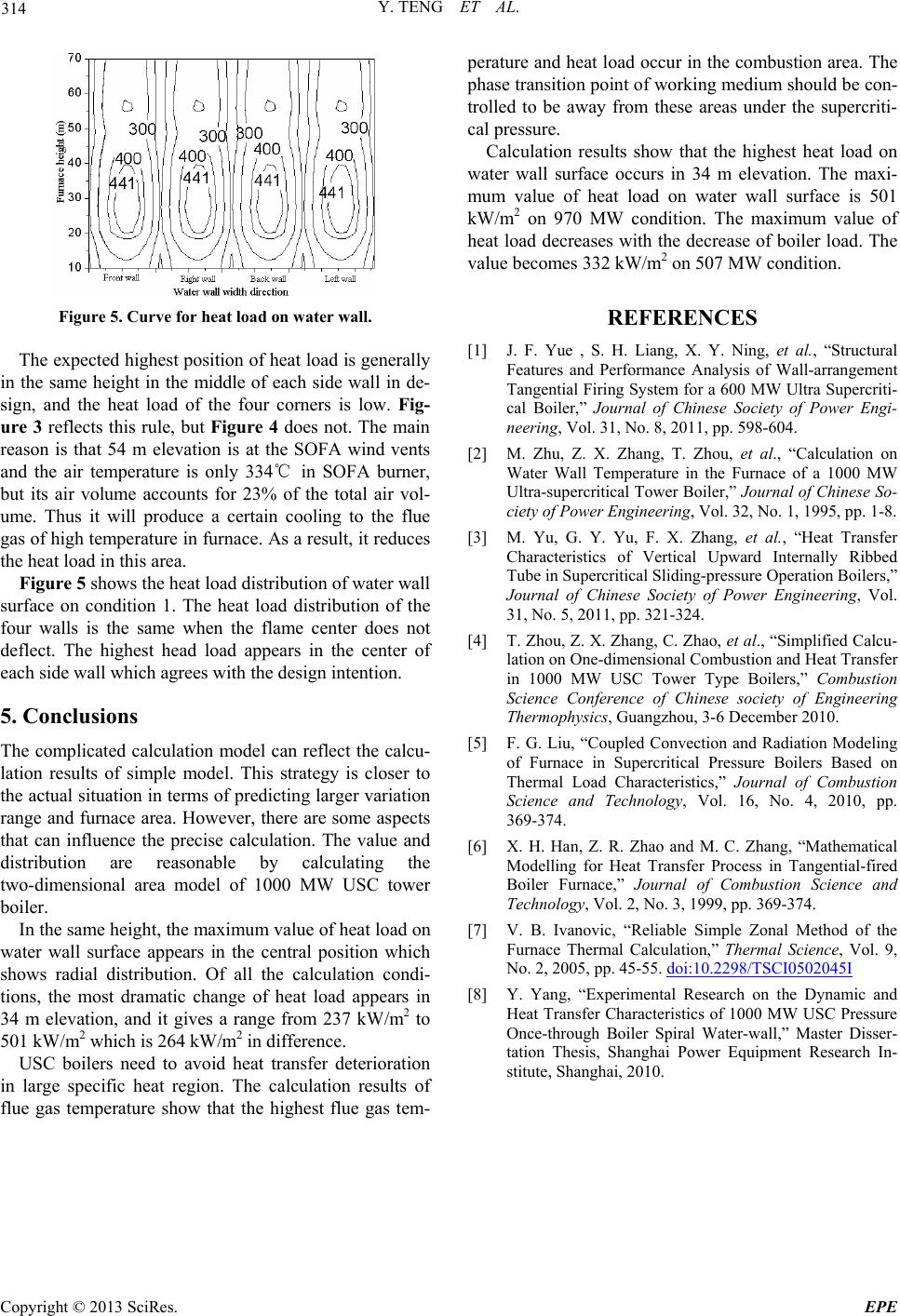 Y. TENG ET AL. Copyright © 2013 SciRes. EPE 314 Figure 5. Curve for heat load on water wall. The expected highest position of heat load is generally in the same height in the middle of each side wall in de- sign, and the heat load of the four corners is low. Fig- ure 3 reflects this rule, but Figure 4 does not. The main reason is that 54 m elevation is at the SOFA wind vents and the air temperature is only 334℃ in SOFA burner, but its air volume accounts for 23% of the total air vol- ume. Thus it will produce a certain cooling to the flue gas of high temperature in furnace. As a result, it reduces the heat load in this area. Figure 5 shows the heat load distribution of water wall surface on condition 1. The heat load distribution of the four walls is the same when the flame center does not deflect. The highest head load appears in the center of each side wall which agrees with the design intention. 5. Conclusions The complicated calculation model can reflect the calcu- lation results of simple model. This strategy is closer to the actual situation in terms of predicting larger variation range and furnace area. However, there are some aspects that can influence the precise calculation. The value and distribution are reasonable by calculating the two-dimensional area model of 1000 MW USC tower boiler. In the same height, the maximum value of heat load on water wall surface appears in the central position which shows radial distribution. Of all the calculation condi- tions, the most dramatic change of heat load appears in 34 m elevation, and it gives a range from 237 kW/m2 to 501 kW/m2 which is 264 kW/m2 in difference. USC boilers need to avoid heat transfer deterioration in large specific heat region. The calculation results of flue gas temperature show that the highest flue gas tem- perature and heat load occur in the combustion area. The phase transition point of working medium should be con- trolled to be away from these areas under the supercriti- cal pressure. Calculation results show that the highest heat load on water wall surface occurs in 34 m elevation. The maxi- mum value of heat load on water wall surface is 501 kW/m2 on 970 MW condition. The maximum value of heat load decreases with the decrease of boiler load. The value becomes 332 kW/m2 on 507 MW condition. REFERENCES [1] J. F. Yue , S. H. Liang, X. Y. Ning, et al., “Structural Features and Performance Analysis of Wall-arrangement Tangential Firing System for a 600 MW Ultra Supercriti- cal Boiler,” Journal of Chinese Society of Power Engi- neering, Vol. 31, No. 8, 2011, pp. 598-604. [2] M. Zhu, Z. X. Zhang, T. Zhou, et al., “Calculation on Water Wall Temperature in the Furnace of a 1000 MW Ultra-supercritical Tower Boiler,” Journal of Chinese So- ciety of Power Engineering, Vol. 32, No. 1, 1995, pp. 1-8. [3] M. Yu, G. Y. Yu, F. X. Zhang, et al., “Heat Transfer Characteristics of Vertical Upward Internally Ribbed Tube in Supercritical Sliding-pressure Operation Boilers,” Journal of Chinese Society of Power Engineering, Vol. 31, No. 5, 2011, pp. 321-324. [4] T. Zhou, Z. X. Zhang, C. Zhao, et al., “Simplified Calcu- lation on One-dimensional Combustion and Heat Transfer in 1000 MW USC Tower Type Boilers,” Combustion Science Conference of Chinese society of Engineering Thermophysics, Guangzhou, 3-6 December 2010. [5] F. G. Liu, “Coupled Convection and Radiation Modeling of Furnace in Supercritical Pressure Boilers Based on Thermal Load Characteristics,” Journal of Combustion Science and Technology, Vol. 16, No. 4, 2010, pp. 369-374. [6] X. H. Han, Z. R. Zhao and M. C. Zhang, “Mathematical Modelling for Heat Transfer Process in Tangential-fired Boiler Furnace,” Journal of Combustion Science and Technology, Vol. 2, No. 3, 1999, pp. 369-374. [7] V. B. Ivanovic, “Reliable Simple Zonal Method of the Furnace Thermal Calculation,” Thermal Science, Vol. 9, No. 2, 2005, pp. 45-55. doi:10.2298/TSCI0502045I [8] Y. Yang, “Experimental Research on the Dynamic and Heat Transfer Characteristics of 1000 MW USC Pressure Once-through Boiler Spiral Water-wall,” Master Disser- tation Thesis, Shanghai Power Equipment Research In- stitute, Shanghai, 2010. |