

Paper Menu >>
Journal Menu >>
 Energy and Power Engineering, 2013, 5, 306-310 doi:10.4236/epe.2013.54B060 Published Online July 2013 (http://www.scirp.org/journal/epe) Numerical Modelling of Coal Combustion Processes in the Vortex Furnace with Dual-Port Loading I. S. Anufriev1, E. P. Kopyev2, D. V. Krasinsky1, V. V. Salomatov1,2, E. Y. Shadrin2, O. V. Sharypov1,2 1Kutateladze Institute of Thermophysics, Siberian Branch of Russian Academy of Sciences, Novosibirsk, Russia 2Novosibirsk State University, Novosibirsk, Russia Email: [email protected] Received March, 2013 ABSTRACT The work is devoted to numerical simulation of pulverized-coal combustion processes in the vortex furnace which is a prospective design of a boiler unit for thermal power plants. New modification of this design characterized by addi- tional tangential-injection nozzle located at the bottom of combustion chamber has been studied. Numerical results for the case of Siberian brown coal combustion in this vortex furnace with dual-port loading are presented, including 3-D aerodynamic structure, the fields of temperatures, radiated heat fluxes, species and dispersed phase concentrations, and NOx emissions. Keywords: Vortex Furnace, Pulverized-Coal Combustion, Numerical Modelling 1. Introduction One of prospective technologies to improve the heat transfer efficiency and ecological performance of boiler units for thermal power plants utilizing low-grade coals is the use of furnace devices with vertical jet pulver- ized-coal combustion. As a kind of these devices, the so-called vortex furnace has been considered. The vortex furnace design shown in Figure 1 usually comprises the vortex combustion chamber in the lower part of the fur- nace, the diffuser, and the cooling chamber exited with discharge flue. With this the pulverized coal-air mixture is injected tangentially (alongside the main vortex flow in the combustion chamber) via rectangular nozzle lo- cated in the upper part of combustion chamber, i.e. via the upper loading port. For the initial vortex furnace de- sign with only upper nozzle injection, the complex ex- perimental and numerical study of interior aerodynamics and turbulent flow features has been carried out at labo- ratory-scale vortex furnace model in isothermal formula- tion earlier by authors [1]. In the presented work a new modification of this design, proposed also by authors [2] and characterized by additional tangential-injection noz- zle located horizontally at the bottom of combustion chamber (bottom loading port), has been studied nu- merically with comprehensive combustion model for the full-scale furnace configuration. In this new vortex fur- nace design with dual-port loading, the stable swirl flow inside the combustion chamber is fo rmed by two tangen- tial jets of coal-air mixture released from the upper and the bottom nozzles. The other distinguishing features of new vortex furnace design are: the ratio of the diffuser throat width to effective diameter D0 of vortex combus- tion chamber is Hx = 0.4; the centers of semi-orifices (comprising the frontal and back walls in XY-section of the vortex chamber) are displaced between each other strictly along vertical line (Figure 1). The following advantages of new vortex furnace de- sign can be indicated: – the compact mass-dimensional parameters, – the distributed (between the upper and the bottom nozzles) tangential input of air or fuel-air mixture, which also provides more flexibility to control the fur- nace working regime, – the horizontal direction of the axis of rotation which facilitates the completeness of coal Figure 1. Scheme of the vortex furnace new design (upper part of the cooling chamber is not shown). Copyright © 2013 SciRes. EPE 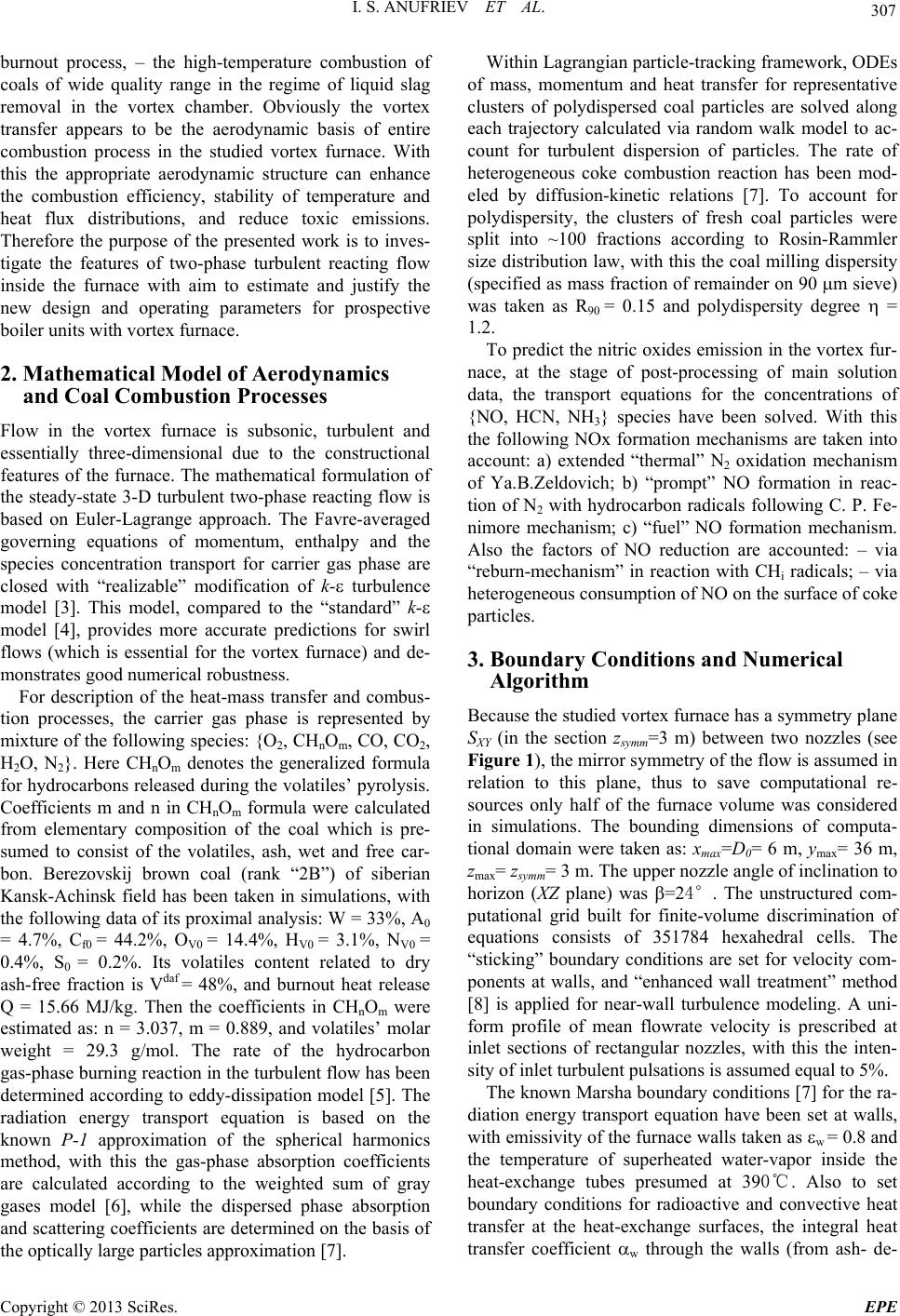 I. S. ANUFRIEV ET AL. 307 burnout process, – the high-temperature combustion of coals of wide quality range in the regime of liquid slag removal in the vortex chamber. Obviously the vortex transfer appears to be the aerodynamic basis of entire combustion process in the studied vortex furnace. With this the appropriate aerodynamic structure can enhance the combustion efficiency, stability of temperature and heat flux distributions, and reduce toxic emissions. Therefore the purpose of the presented work is to inves- tigate the features of two-phase turbulent reacting flow inside the furnace with aim to estimate and justify the new design and operating parameters for prospective boiler units with vortex furnace. 2. Mathematical Model of Aerodynamics and Coal Combustion Processes Flow in the vortex furnace is subsonic, turbulent and essentially three-dimensional due to the constructional features of the furnace. The mathematical formulation of the steady-state 3-D turbulent two-phase reacting flow is based on Euler-Lagrange approach. The Favre-averaged governing equations of momentum, enthalpy and the species concentration transport for carrier gas phase are closed with “realizable” modification of k- turbulence model [3]. This model, compared to the “standard” k- model [4], provides more accurate predictions for swirl flows (which is essential for the vortex furnace) and de- monstrates good numerical robustness. For description of the heat-mass transfer and combus- tion processes, the carrier gas phase is represented by mixture of the following sp ecies: {O2, CHnOm, CO, CO2, H2O, N2}. Here CHnOm denotes the generalized formula for hydrocarbons released during the volatiles’ pyro lysis. Coefficients m and n in CHnOm formula were calculated from elementary composition of the coal which is pre- sumed to consist of the volatiles, ash, wet and free car- bon. Berezovskij brown coal (rank “2B”) of siberian Kansk-Achinsk field has been taken in simulations, with the following data of its proximal analysis: W = 33 %, A0 = 4.7%, Cf0 = 44.2%, OV0 = 14.4%, HV0 = 3.1%, NV0 = 0.4%, S0 = 0.2%. Its volatiles content related to dry ash-free fraction is Vdaf = 48%, and burnout heat release Q = 15.66 MJ/kg. Then the coefficients in CHnOm were estimated as: n = 3.037, m = 0.889, and volatiles’ molar weight = 29.3 g/mol. The rate of the hydrocarbon gas-phase burning reaction in the turbulent flow has been determined according to eddy-dissipation model [5]. The radiation energy transport equation is based on the known P-1 approximation of the spherical harmonics method, with this the gas-phase absorption coefficients are calculated according to the weighted sum of gray gases model [6], while the dispersed phase absorption and scattering coefficients are determined on the basis of the optically large particles approximatio n [7]. Within Lagrangian particle-tracking framework, ODEs of mass, momentum and heat transfer for representative clusters of polydispersed coal particles are solved along each trajectory calculated via random walk model to ac- count for turbulent dispersion of particles. The rate of heterogeneous coke combustion reaction has been mod- eled by diffusion-kinetic relations [7]. To account for polydispersity, the clusters of fresh coal particles were split into ~100 fractions according to Rosin-Rammler size distribution law, with this the co al milling dispersity (specified as mass fraction of remainder on 90 m sieve) was taken as R90 = 0.15 and polydispersity degree = 1.2. To predict the nitric oxides emission in the vortex fur- nace, at the stage of post-processing of main solution data, the transport equations for the concentrations of {NO, HCN, NH3} species have been solved. With this the following NOx formation mechanisms are taken into account: a) extended “thermal” N2 oxidation mechanism of Ya.B.Zeldovich; b) “prompt” NO formation in reac- tion of N2 with hydrocarbon radicals following C. P. Fe- nimore mechanism; c) “fuel” NO formation mechanism. Also the factors of NO reduction are accounted: – via “reburn-mechanism” in reaction with CHi radicals; – via heterogeneous consumption of NO on the surface of coke particles. 3. Boundary Conditions and Numerical Algorithm Because the studied vortex furnace has a symmetry plane SXY (in the section zsymm=3 m) between two nozzles (see Figure 1), the mirror symmetry of the flow is assumed in relation to this plane, thus to save computational re- sources only half of the furnace volume was considered in simulations. The bounding dimensions of computa- tional domain were taken as: xmax=D0= 6 m, ymax= 36 m, zmax= zsymm= 3 m. The upper nozzle angle of inclination to horizon (XZ plane) was =24°. The unstructured com- putational grid built for finite-volume discrimination of equations consists of 351784 hexahedral cells. The “sticking” boundary conditions are set for velocity com- ponents at walls, and “enhanced wall treatment” method [8] is applied for near-wall turbulence modeling. A uni- form profile of mean flowrate velocity is prescribed at inlet sections of rectangular nozzles, with this the inten- sity of inlet turbulen t pulsations is assumed equal to 5%. The known Marsha bound ary conditions [7] f or the ra- diation energy transport equation have been set at walls, with emissivity of the furnace walls taken as w = 0.8 and the temperature of superheated water-vapor inside the heat-exchange tubes presumed at 390℃. Also to set boundary conditions for radioactive and convective heat transfer at the heat-exchange surfaces, the integral heat transfer coefficient w through the walls (from ash- de- Copyright © 2013 SciRes. EPE 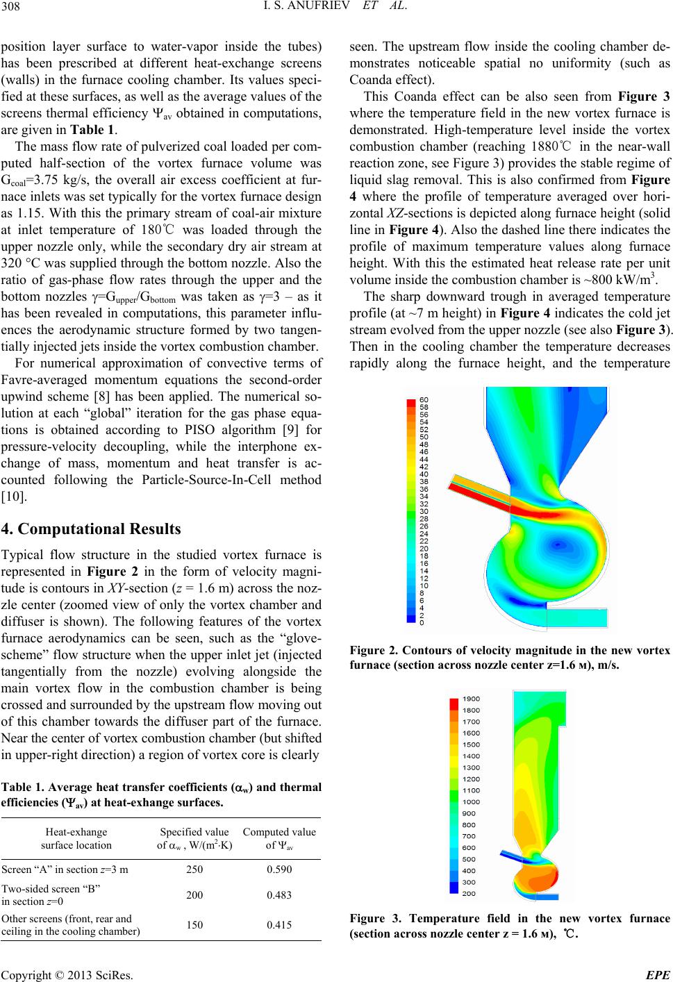 I. S. ANUFRIEV ET AL. 308 position layer surface to water-vapor inside the tubes) has been prescribed at different heat-exchange screens (walls) in the furnace cooling chamber. Its values speci- fied at these surfaces, as well as the average values of the screens thermal efficiency av obtained in computations, are given in Table 1. The mass flow rate of pulverized coal loaded per com- puted half-section of the vortex furnace volume was Gcoal=3.75 kg/s, the overall air excess coefficient at fur- nace inlets was set typically for the vortex furnace design as 1.15. With this the primary stream of coal-air mixture at inlet temperature of 180℃ was loaded through the upper nozzle only, while the secondary dry air stream at 320 C was supplied through th e bottom nozzle. Also the ratio of gas-phase flow rates through the upper and the bottom nozzles =Gupper/Gbottom was taken as =3 – as it has been revealed in computations, this parameter influ- ences the aerodynamic structure formed by two tangen- tially injected jets insid e the vortex combustion chamber. For numerical approximation of convective terms of Favre-averaged momentum equations the second-order upwind scheme [8] has been applied. The numerical so- lution at each “global” iteration for the gas phase equa- tions is obtained according to PISO algorithm [9] for pressure-velocity decoupling, while the interphone ex- change of mass, momentum and heat transfer is ac- counted following the Particle-Source-In-Cell method [10]. 4. Computational Results Typical flow structure in the studied vortex furnace is represented in Figure 2 in the form of velocity magni- tude is contours in XY-section (z = 1.6 m) across the noz- zle center (zoomed view of only the vortex chamber and diffuser is shown). The following features of the vortex furnace aerodynamics can be seen, such as the “glove- scheme” flow structure when the upper inlet jet (injected tangentially from the nozzle) evolving alongside the main vortex flow in the combustion chamber is being crossed and surrounded by the upstream flow moving out of this chamber towards the diffuser part of the furnace. Near the center of vortex combustion chamber (but shifted in upper-right di rect ion) a region of vortex core is clearly Table 1. Average heat transfer coefficients (w) and thermal efficiencies (av) at heat-exhange surfaces. Heat-exhange surface location Specified value of w , W/(m2K) Computed value of av Screen “A” in section z=3 m 250 0.590 Two-sided screen “B” in section z=0 200 0.483 Other screens (front , rear and ceiling in the cooling chamber) 150 0.415 seen. The upstream flow inside the cooling chamber de- monstrates noticeable spatial no uniformity (such as Coanda effect). This Coanda effect can be also seen from Figure 3 where the temperature field in the new vortex furnace is demonstrated. High-temperature level inside the vortex combustion chamber (reaching 1880℃ in the near-wall reaction zone, see Figure 3) provides th e stable regime of liquid slag removal. This is also confirmed from Figure 4 where the profile of temperature averaged over hori- zontal XZ-sections is depicted along furnace height (solid line in Figure 4). Also the dashed line there indicates the profile of maximum temperature values along furnace height. With this the estimated heat release rate per unit volume inside the combustion chamber is ~800 kW/m3. The sharp downward trough in averaged temperature profile (at ~7 m height) in Figure 4 indicates the cold jet stream evolved from the upper nozzle (see also Figure 3). Then in the cooling chamber the temperature decreases rapidly along the furnace height, and the temperature Figure 2. Contours of velocity magnitude in the new vortex furnace (section across nozzle center z=1.6 м), m/s. Figure 3. Temperature field in the new vortex furnace (section across nozzle center z = 1.6 м), ℃. Copyright © 2013 SciRes. EPE 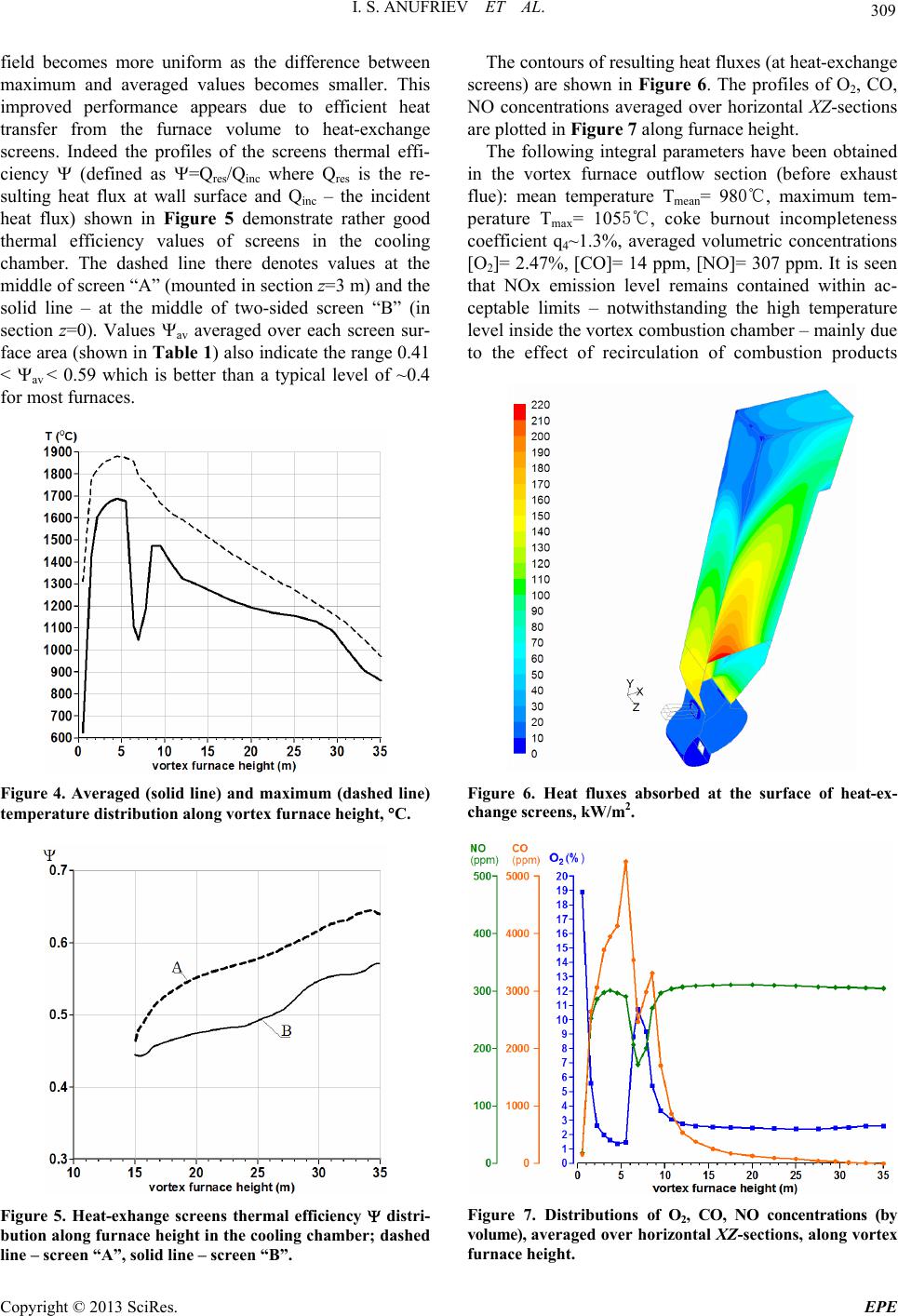 I. S. ANUFRIEV ET AL. 309 field becomes more uniform as the difference between maximum and averaged values becomes smaller. This improved performance appears due to efficient heat transfer from the furnace volume to heat-exchange screens. Indeed the profiles of the screens thermal effi- ciency (defined as =Qres/Qinc where Qres is the re- sulting heat flux at wall surface and Qinc – the incident heat flux) shown in Figure 5 demonstrate rather good thermal efficiency values of screens in the cooling chamber. The dashed line there denotes values at the middle of screen “A” (mounted in section z=3 m) and the solid line – at the middle of two-sided screen “B” (in section z=0). Values av averaged over each screen sur- face area (shown in Table 1) also indicate the range 0.41 < av < 0.59 which is better than a typical level of ~0.4 for most furnaces. Figure 4. Averaged (solid line) and maximum (dashed line) temperature distribution along vortex furnace height, C. Figure 5. Heat-exhange screens thermal efficiency distri- bution along furnace height in the cooling chamber; dashed line – screen “A”, solid line – screen “B”. The contours of resulting heat fluxes (at heat-exchange screens) are shown in Figure 6. The profiles of O2, CO, NO concentrations averaged over horizontal XZ-sections are plotted in Figure 7 along furnace height. The following integral parameters have been obtained in the vortex furnace outflow section (before exhaust flue): mean temperature Tmean= 980℃, maximum tem- perature Tmax= 1055℃, coke burnout incompleteness coefficient q4~1.3%, averaged volumetric concentrations [O2]= 2.47%, [CO]= 14 ppm, [NO]= 307 ppm. It is seen that NOx emission level remains contained within ac- ceptable limits – notwithstanding the high temperature level inside the vortex combustion chamber – mainly due to the effect of recirculation of combustion products Figure 6. Heat fluxes absorbed at the surface of heat-ex- change screens, kW/m2. Figure 7. Distributions of O2, CO, NO concentrations (by volume), averaged over horizontal XZ-sections, along vortex furnace height. Copyright © 2013 SciRes. EPE  I. S. ANUFRIEV ET AL. Copyright © 2013 SciRes. EPE 310 towards reaction zones inside the vortex chamber. Also the improved thermal efficiency of heat-exchange screens in the cooling chamber has been demonstrated. 5. Conclusions The numerical simulation of 3-D aerodynamics and pul- verized brown coal combustion processes in the new vortex furnace configuration with dual-port loading has been performed, and detailed flow field information in- cluding the flow structure, the fields of temperatures, radiated heat fluxes, species and dispersed phase concen- trations have been obtained. With this it has been shown that the integral heat engineering and ecological parame- ters of new vortex furnace meet the ranges corresponding to engineering practice. 6. Acknowledgements Computations have been performed with the use of CFD package FLUENT at the supercomputer clusters NKS-160 and NKS-30T (SSCC SB RAS, Novosibirsk, Russia). The work has been supported by Russian Minis- try of Education and Science (Agreement No. 8187). REFERENCES [1] V. V. Salomatov, D. V. Krasinsky, Yu. A. Anikin, I. S. Anufriev, O. V. Sharypov and Kh. Enkhjargal, “Experi- mental and Numerical Investigation of Aerodynamic Characteristics of Swirling Flows in a Model of the Swirl- ing-type Furnace of a Steam Generator,” J. of Engineer- ing Physics and Thermophysics, Vol. 85, No. 2, 2012, pp. 282-293.doi:10.1007/s10891-012-0651-8 [2] N. V. Golovanov, V. E. Nakoryakov, A. P. Burdukov, V. V. Salomatov and A. A. Dorozhkov, “Vortex Furnace,” Russian Federation patent No.2042084, 1995 (in Rus- sian). [3] T.-H. Shih, W. W. Liou, A. Shabbir, Z. Yang and J. Zhu “A New k- Eddy-Viscosity Model for High Reynolds Number Turbulent Flows – Model Development and Va- lidation,” Computers&Fluids –Vol. 24, No. 3, 1995, pp. 227-238. doi:10.1016/0045-7930(94)00032-T [4] B. E. Launder and D. B. Spalding, “Lectures in Mathe- matical Models of Turbulence,” London (England): Aca- demic Press, 1972. [5] B. F. Magnussen, “The Eddy Dissipation Concept,” IEA, 1989. [6] T. F. Smith, Z. F. Shen and J. N. Friedman “Evaluation of Coefficients for the Weighted Sum of Gray Gases Mod- el,” Proceedings of XX-th National ASME-AIChE Heat Transfer Conference, Milwakee, USA, August 2-5, 1981. [7] E. P. Volkov, L. I. Zaichik and V. A. Pershukov, “Model- ling the Solid Fuel Combustion,” Moscow: Nauka, 1994 (in Russian). [8] FLUENT 6.3 User’s Guide, Fluent Inc., 2006. [9] R. I. Issa, “Solution of Implicitly Discretized Fluid Flow Equations by Operator Splitting,” Journal of Computa- tional Physics, Vol. 62, No. 1, 1986, pp. 40-65. doi:10.1016/0021-9991(86)90099-9 [10] C. T. Crowe, M. P. Sharma and D. E. Stock, “The Particle-Source-In-Cell (PSI-CELL) model for gas-droplet flows,” ASME Journal of Fluids Engi- neering, Vol. 99, No. 2, 1977, pp. 325-332. doi:10.1115/1.3448756 |