

Paper Menu >>
Journal Menu >>
 Energy and Power Engineering, 2013, 5, 300-305 doi:10.4236/epe.2013.54B059 Published Online July 2013 (http://www.scirp.org/journal/epe) Energy and Exergy Analysis of a New Small Concentr a ti ng Solar Power Plant Heng-Yi Li, Tsair-Fuh Huang, Meng-Chang Tsai, Yung-Woou Lee, Shing-Lei Yuan, Ming-Jui Tsai, Chi-Fong Ai Physics Division, Institute of Nuclear Energy Research, Taoyuan, Chinese Taipei Email: [email protected] Received March, 2013 ABSTRACT A new small concentrating solar power plant which is suitable for urban area is presented, and a theoretical framework for the energy and exergy analysis in the overall power plant is also constructed. The framework can be used to evaluate the energy and exergy losses in each component. Furthermore, the energy and exergy efficiencies have also been com- puted and compared for the individual components as well as for the overall plant. Keywords: Exergy Analysis; Concentrating Solar Power; Thermal Energy Storage; Stirling Engine 1. Introduction In the present world, the daily primary energy source is fossil fuels such as coal, petroleum and natural gas. They are not only limited in the earth but also release gaseous or liquid pollutants during operation. Because solar en- ergy is an inexhaustible, clean and safe source of energy, it has received much attention as one of the most prom- ising candidate to substitute for the conventional fuels for electricity supply. Taiwan is located in subtropical zone, rich in solar energy resources. However, Taiwan is mostly mountainous in the east, with gently sloping plains in the west. Hence, the installation area for solar power plant is limited. Recently, rapid development occurred worldwide in the basic technology and market strategy for the concen- trating solar power (CSP) technologies, including para- bolic trough, power tower, and dish/engine. However, the power generation efficiencies of the CSP systems are found to be low, which indirectly increases the capital costs of electricity generation, and great efforts have to be concentrated on the future research and development of CSP systems. Dish–Stirling systems have demon- strated the good efficiency of any solar power generation system by converting nearly 30% of the direct-normal incident solar radiation into electricity after accounting for parasitic power losses. Furthermore, solar-powered Stirling engines can operate at low, medium, and high temperatures. Hence, the feasibility of a solar power sys- tem based on the Stirling dish and current status for commercial markets are very attractive compared with other concentrated technology [1-3]. However, the gen- eral solar dish Stirling engine systems do not contain thermal energy storage (TES), so their power production is influenced by the weather. TES involves the temporary storage of high or low temperature thermal energy for later use. It is an excel- lent candidate to offset the mismatch between thermal energy availability and demand. For example, storage of solar energy is used for overnight heating. TES systems achieve benefits by fulfilling one or more of the follow- ing purposes: increase generation capacity, enable better operation of cogeneration plants, shift energy purchases to low cost periods, increase system reliability and inte- gration with other functions [4]. TES options for CSP plants are classified to three categories: sensible, latent, and thermo chemical storage. The only TES that cur- rently operates with multiple hours of storage is the sen- sible, two-tank, molten salt system. The system has demonstrated reliable operation at commercial scale [5]. Generally, the performance of thermal power plants is evaluated through energetic performance criteria based on first law of thermodynamics, including electrical power and thermal efficiency. In recent decades, the ex- egetic performance based on the second law of thermo- dynamics has found as useful method in the design, evaluation, optimization and improvement of thermal power plants. The exegetic performance analysis can not only determine magnitudes, location and causes of irre- versibilities in the plants, but also provides more mean- ingful assessment of plant individual components effi- ciency. These points of the exegetic performance analy- sis are the basic differences from energetic performance analysis. Therefore, it can be said that performing exe- Copyright © 2013 SciRes. EPE 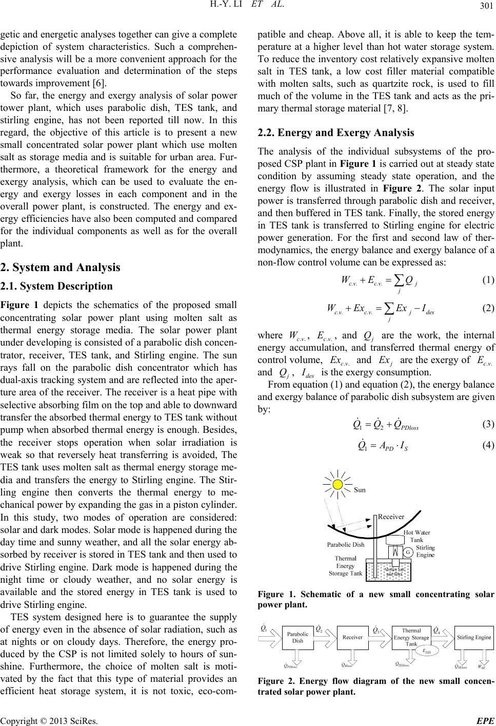 H.-Y. LI ET AL. 301 getic and energetic analyses together can give a complete depiction of system characteristics. Such a comprehen- sive analysis will be a more convenient approach for the performance evaluation and determination of the steps towards improvement [6]. So far, the energy and exergy analysis of solar power tower plant, which uses parabolic dish, TES tank, and stirling engine, has not been reported till now. In this regard, the objective of this article is to present a new small concentrated solar power plant which use molten salt as storage media and is suitable for urban area. Fur- thermore, a theoretical framework for the energy and exergy analysis, which can be used to evaluate the en- ergy and exergy losses in each component and in the overall power plant, is constructed. The energy and ex- ergy efficiencies have also been computed and compared for the individual components as well as for the overall plant. 2. System and Analysis 2.1. System Description Figure 1 depicts the schematics of the proposed small concentrating solar power plant using molten salt as thermal energy storage media. The solar power plant under developing is consisted of a parabolic dish concen- trator, receiver, TES tank, and Stirling engine. The sun rays fall on the parabolic dish concentrator which has dual-axis tracking system and are reflected into the aper- ture area of the receiver. The receiver is a heat pipe with selective absorbing film on the top and able to downward transfer the absorbed thermal energy to TES tank without pump when absorbed thermal energy is enough. Besides, the receiver stops operation when solar irradiation is weak so that reversely heat transferring is avoided, The TES tank uses molten salt as thermal energy storage me- dia and transfers the energy to Stirling engine. The Stir- ling engine then converts the thermal energy to me- chanical power by expanding the gas in a piston cylinder. In this study, two modes of operation are considered: solar and dark modes. Solar mode is happened during the day time and sunny weather, and all the solar energy ab- sorbed by receiver is stored in TES tank and then used to drive Stirling engine. Dark mode is happened during the night time or cloudy weather, and no solar energy is available and the stored energy in TES tank is used to drive Stirling engine. TES system designed here is to guarantee the supply of energy even in the absence of solar radiation, such as at nights or on cloudy days. Therefore, the energy pro- duced by the CSP is not limited solely to hours of sun- shine. Furthermore, the choice of molten salt is moti- vated by the fact that this type of material provides an efficient heat storage system, it is not toxic, eco-com- patible and cheap. Above all, it is able to keep the tem- perature at a higher level than hot water storage system. To reduce the inventory cost relatively expansive molten salt in TES tank, a low cost filler material compatible with molten salts, such as quartzite rock, is used to fill much of the volume in the TES tank and acts as the pri- mary thermal storage material [7, 8]. 2.2. Energy and Exergy Analysis The analysis of the individual subsystems of the pro- posed CSP plant in Figure 1 is carried out at steady state condition by assuming steady state operation, and the energy flow is illustrated in Figure 2. The solar input power is transferred through parabolic dish and receiver, and then buffered in TES tank. Finally, the stored energy in TES tank is transferred to Stirling engine for electric power generation. For the first and second law of ther- modynamics, the energy balance and exergy balance of a non-flow control volume can be expressed as: c.v. c.v.j j WE Q (1) c.v.c.v.j des j WEx ExI (2) where ..cv , ..cv , and W E j Q are the work, the internal energy accumulation, and transferred thermal energy of control volume, ..cv and Ex j Ex are the exergy of and ..cv E j Q, des I is the exergy consumption. From equation (1) and equation (2), the energy balance and exergy balance of parabolic dish subsystem are given by: 12 P Dloss QQQ (3) 1 P DS QAI (4) Figure 1. Schematic of a new small concentrating solar power plant. 1 Q 2 Q 3 Q 4 Q SEloss Q SE W PDloss Q Rloss Q TESloss Q TES E Figure 2. Energy flow diagram of the new small concen- trated solar power plant. Copyright © 2013 SciRes. EPE 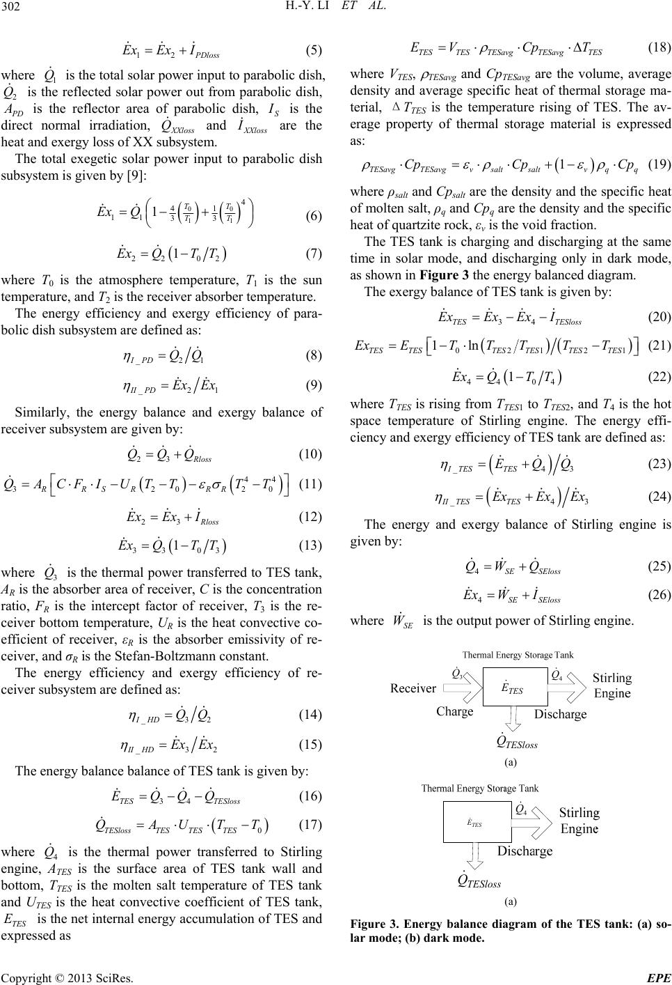 H.-Y. LI ET AL. 302 12 P Dloss Ex I Ex (5) where is the total solar power inpu 1 Q he t to parabolic dish, 2 Q is t reflected solar power out from parabolic dish, P D A is the reflector area of parabolic dish, S I is the ct normal irradiation, XXloss Q and XXloss I re the heat and exergy loss of XX sm. The total exegetic solar power input dire a ubsyste to parabolic dish subsystem is given by [9]: 00 11 4 41 11 33 1TT TT ExQ (6) 22 02 1ExQT T (7) where T0 is the atmosphere temperature1 bo , T is the sun temperature, and T2 is the receiver absorber temperature. The energy efficiency and exergy efficiency of para- lic dish subsystem are defined as: _2IPD QQ 1 (8) _2II PDEx Ex 1 (9) Similarly, the energy balance and e re xergy balance of ceiver subsystem are given by: 23 R loss QQQ (10) 20 (11) 44 320RRSR RR QACFIUTT TT 23 R loss ExEx I (12) 33 03 1ExQT T (13) where is the thermal power transferred to TES tank, of re- ce 3 Q e aAR is thbsorber area of receiver, C is the concentration ratio, FR is the intercept factor of receiver, T3 is the re- ceiver bottom temperature, UR is the heat convective co- efficient of receiver, εR is the absorber emissivity of re- ceiver, and σR is the Stefan-Boltzmann constant. The energy efficiency and exergy efficiency iver subsystem are defined as: _3IHD QQ 2 (14) _3II HDExEx 2 (15) The energy balance balance of TES tank is given by: ) T (17) where is the thermal power transferred to Stirling 34TES TESloss EQQQ (16 0TESlossTES TESTES QAUT 4 Q AT engine, ES is the surface area of TES tank wall and bottom, TTES is the molten salt temperature of TES tank and UTES is the heat convective coefficient of TES tank, TES E is the net internal energy accumulation of TES and ssed as TE E expre STES TESavgTESavgTES VCp T (18) where VTES, TESavg and CpTESavg are the volu (19) where ρsalt and Cpsalt are the density and the specifi (20) me, average density and average specific heat of thermal storage ma- terial, ΔTTES is the temperature rising of TES. The av- erage property of thermal storage material is expressed as: 1 TESavgTESavgv saltsaltv qq CpCp Cp c heat of molten salt, ρq and Cpq are the density and the specific heat of quartzite rock, εv is the void fraction. The TES tank is charging and discharging at the same time in solar mode, and discharging only in dark mode, as shown in Figure 3 the energy balanced diagram. The exergy balance of TES tank is given by: 34TES TESloss ExEx Ex I 021 1ln TESTESTES TESTES ExETTTT 21TES T (21) 44 04 1ExQT T ( where TTES is rising from TTES1 to TTES 22) 2, and T4 is the hot space temperature of Stirling engine. The energy effi- ciency and exergy efficiency of TES tank are defined as: _43ITES TES EQQ (23) _4II TESTES ExExEx 3 The energy and exergy balance of Stir gi (25) where is the output power of St (24) ling engine is ven by: 4SE SEloss QW Q 4SE SEloss Ex WI (26) SE W irling engine. 3 Q 4 Q TESloss Q TES E (a) 4 Q TESloss Q TES E (a) Figure 3. Energy balance dim of the TES tank: (a) so- lar mode; (b) dark mode. agra Copyright © 2013 SciRes. EPE 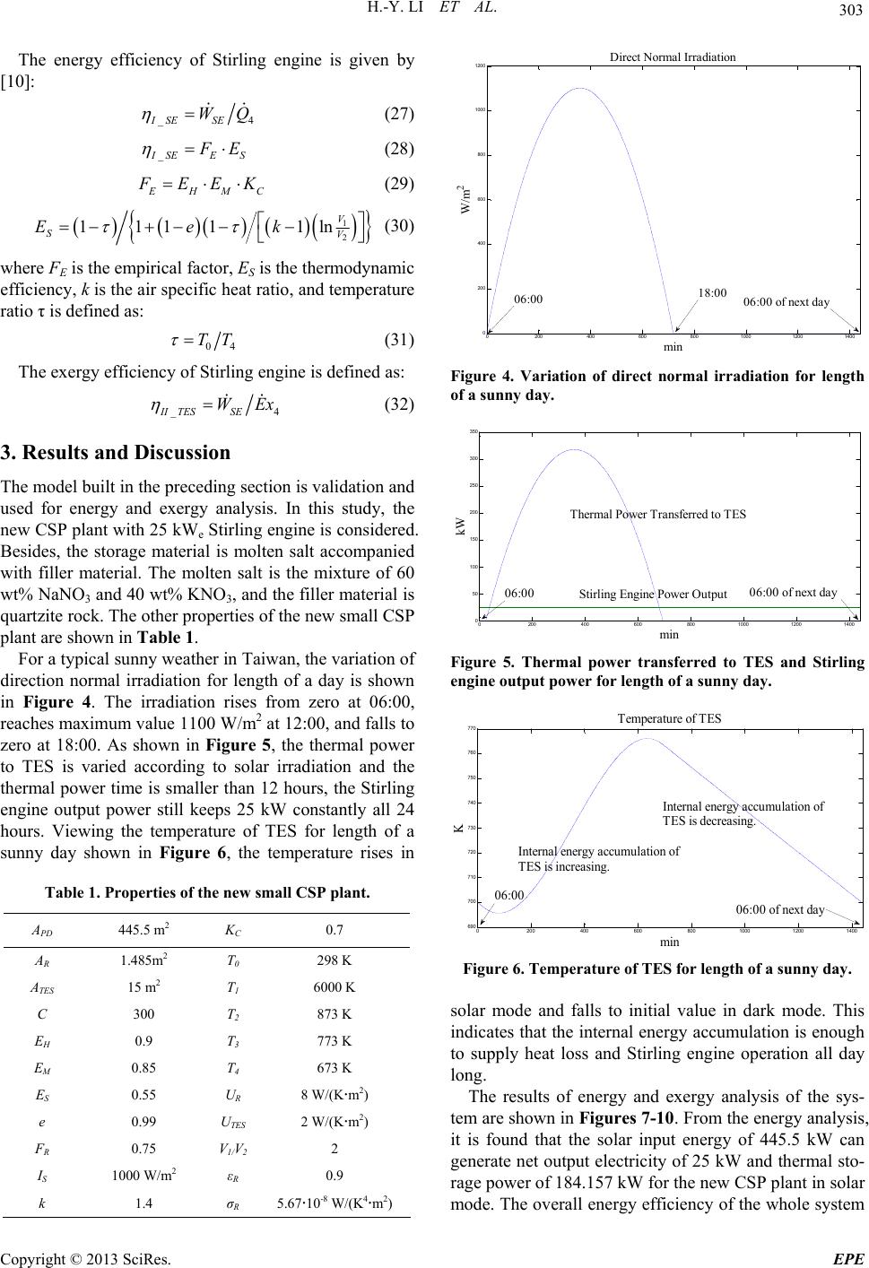 H.-Y. LI ET AL. 303 The energy efficiency of Stirling engine is given by [10]: _4ISE SE WQ (27) _ I SEE S F E (28) E HM C F EEK (29) 1 1ln V V k (30) 2 1111 S Ee where FE is the empirical factor, ES is the thermodynamic efficiency, k is the air specific heat ratio, and temperature ratio τ is defined as: 04 TT (31) The exergy efficiency of Stirling engine is defined as: _4II TESSE WEx (32) 3. Results and Discussion section is validation and A The model built in the preceding used for energy and exergy analysis. In this study, the new CSP plant with 25 kWe Stirling engine is considered. Besides, the storage material is molten salt accompanied with filler material. The molten salt is the mixture of 60 wt% NaNO3 and 40 wt% KNO3, and the filler material is quartzite rock. The other properties of the new small CSP plant are shown in Table 1. For a typical sunny weather in Taiwan, the variation of direction normal irradiation for length of a day is shown in Figure 4. The irradiation rises from zero at 06:00, reaches maximum value 1100 W/m2 at 12:00, and falls to zero at 18:00. As shown in Figure 5, the thermal power to TES is varied according to solar irradiation and the thermal power time is smaller than 12 hours, the Stirling engine output power still keeps 25 kW constantly all 24 hours. Viewing the temperature of TES for length of a sunny day shown in Figure 6, the temperature rises in Table 1. Properties of the new small CSP plant. PD 445.5 m2 KC 0.7 AR 1.485m2 T0 0200 400 600 800 1000 1200 1400 0 200 400 600 800 1000 1200 min W/m 2 Direct Normdiational Irra 298 K ATES 15 m2 T1 6000 K C 300 T2 873 K EH 0.9 T3 773 K EM 0.85 T4 673 K ES 0.55 UR 8 2) V 10 2 k 1.4 σR 5.6710-8 W/(K4m2) W/(Km e 0.99 UTES 2 W/(Km2) FR 0.75 V1/ 2 2 IS 00 W/mεR 0.9 06:00 18:00 06:00 of next day Figure 4. Variation of direct normal irradiation for length of a sunny day. 0200 4006008001000 1200 1400 0 50 100 150 200 250 300 350 min kW Thermal Power Transferred to TES 06:00 Stirling Engine Power Output06:00 of next day Figure 5. Thermal power transferred to TES and Stirling engine output power for length of a sunny day. 0200 400 600 800100012001400 690 700 710 720 730 740 750 760 770 Temperature of TES min K Internal energy accumulation of TES is decreasing. Internal energy accumulation of TES is increasing. 06:00 06:00 of next day Figure 6. Temperature of TES for length of a sunny day. so s n lar mode and falls to initial value in dark mode. Thi dicates that the internal energy accumulation is enough i to supply heat loss and Stirling engine operation all day long. The results of energy and exergy analysis of the sys- tem are shown in Figures 7-10. From the energy analysis, it is found that the solar input energy of 445.5 kW can generate net output electricity of 25 kW and thermal sto- rage power of 184.157 kW for the new CSP plant in solar mode. The overall energy efficiency of the whole system Copyright © 2013 SciRes. EPE  H.-Y. LI ET AL. 304 is 46.95%. The subsystem energy efficiencies are 75%, 84.96%, 94.98% and 29.25% for parabolic dish subsys- tem, receiver subsystem, TES tank and Stirling engine, respectively. The largest percentage energy loss is 47.12% occurred in parabolic dish subsystem, followed by 25.59% in Stirling engine, 21.26% in receiver sub- system and 6.03 % in TES tank. However, the results of the exergy analysis show a different behavior. The over- all exergy efficiency of the whole system is 30.53%, while the subsystem energy efficiencies are 52.9%, 79.26%, 88.58% and 47.60% for parabolic dish subsys- tem, receiver subsystem, TES tank and Stirling engine, respectively. The largest percentage exergy loss is 67.80% occurred in parabolic dish subsystem, followed by 15.79% in receiver subsystem, 9.52% in Stirling en- gine and 6.89% in TES tank. Thermal and Exergy Eff. for Solar Mode 0.00 10. 00 20. 00 30. 00 40. 00 50. 00 60. 00 70. 00 80. 00 90. 00 1 00. 00 Para. DishReceiverTESSEoverall Th . Ef f ( %) Ex. Eff (%) Figure 7. Comparison of energy and exergy efficiency for solar mode. Thermal and Exergy Loss for Solar Mode 80. 00 0. 00 10. 00 20. 00 30. 00 40. 00 50. 00 60. 00 70. 00 Para. DishReceiverTESSE % Th . L o ss ( %) Ex. Loss (%) Figure 8. Comparison of energy and exergy loss for solar mode. Thermal and Exergy Eff. for Dark Mode 10 Thermal and Exergy Loss for Dark Mode 0.00 10.00 20.00 30.00 40.00 50.00 60.00 70.00 80.00 90.00 100.00 Para. DishReceiverTESSE % Th. Loss (% ) Ex. Loss (% ) Figure 10. Comparison of energy and exergy loss for dark It is found that the TES thermal storage power of 99.718 kW can generate net output electricity of 25 kW for the new CSP plant in dark mode. The overall energy efficiency of the whole system is 25.07%. The subsystem energy efficiencies are 85.71% and 29.25% for TES tank and Stirling engine, respectively. The largest percentage energy loss is 80.93% occurred in Stirling engine, fol- lowed by 19.07% in TES tank. The overall exergy effi- ciency of the whole system is 45.26%, while the s tem energy efficiencies are 95.08% and 47.60% foTES exergy loss is 91.02% occurred in Stirling engine, filler as thermal energy st efficiency and large loss, the system overall efficiency is e help of TES. The TES offers great mode. ubsys- r tank and Stirling engine, respectively. The largest per- entagec followed by 8.98% in TES tank. It can be seen that although Stirling engine has low energy efficiency and large loss, the system overall effi- ciency is not lessened with the help of TES. The TES offers great contribution in both energy and exergy effi- ciency. Furthermore, for high overall efficiency the most significant components requiring careful design and selec- tion are the parabolic dish subsystem and Stirling engine. 4. Conclusions In this study, the exergy and energy analysis of the new CSP plant is considering two modes: solar and dark. The CSP plant using molten salt and orage material is under developing. It is consisted of a parabolic dish concentrator, receiver, TES tank, and Stir- ling engine. The theoretical model is built and verified. The validation reveals that the Stirling engine of the new CSP using TES as an energy buffer can continue to run at full capacity all day long. Furthermore, the analysis re- sults show that although Stirling engine has low energy 0.00 10. 00 20. 00 30. 00 40. 00 50. 00 60. 00 70. 00 80. 00 90. 00 0.00 Para. DishReceiverTESSEoverall Th . E f f ( %) Ex. Eff (%) not lessened with th contribution in both energy and exergy efficiency. Fur- thermore, in CSP design the most significant components requiring careful design and selection are the parabolic dish subsystem and Stirling engine. 5. Acknowledgements Financial support from the budget of Executive Yuan, Figure 9. Comparison of energy and exergy efficiency for dark mode. Copyright © 2013 SciRes. EPE  H.-Y. LI ET AL. Copyright © 2013 SciRes. EPE 305 Taiwan, is greatly appreciated. REFERENCES [1] S. K. Tyagi, S. Wang, M. K. Singhal, S. C. Kaushik and S. R. Park, “Exergy Analysis and Parametric Study of Con- centrating Type Solar Collectors,” International Journal of Thermal Science, Vol. 46, 2007, pp. 1304-1310. doi:10.1016/j.ijthermalsci.2006.11.010 [2] C. Xu, Z. Wang, X. Li and F. Sun, “Energy and Exergy ower Plants,” Applied Thermal 17-18, 2011, pp. 3904-3913. Analysis of Solar Power T Engineering, Vol. 31, No. doi:10.1016/j.applthermaleng.2011.07.038 [3] V. S. Reddy, S. C. Kaushik Analysis and Performance Eva and S. K. Tyagi, “Exerge luation of Parabolic Dish Stirling Engine Solar Power Plant,” International Journal of Energy Res 5500- al Power Plants: A Review,” tic earch, 2012. [4] I. Dincer and M. A. Rosen, “Exergy, Energy, Environ- ment and Sustainable Development,” Elsevier, 2007. [5] G. Glatzmaier, “Summary Report for Concentrating Solar Power Thermal Storage Workshop,” NREL/ TP- 52134, 2011. [6] S. C. Kaushik, V. S. Reddy and S. K. Tyagi, “Energy and Exergy Analyses of Therm Renewable and Sustainable Energy Reviews, Vol. 15, No. 4, 2011, pp. 1857-1872. doi:10.1016/j.rser.2010.12.007 [7] F. Cavallaro, “Fuzzy TOPSIS Approach for Assessing Thermal Energy Storage in Concentrated Solar Power (CSP) Systems,” Applied Energy, Vol. 87, No. 2, 2010, pp. 496-503. doi:10.1016/j.apenergy.2009.07.009 [8] S. Flueckiger, Z. Yang and S. V. Garimella, “An Inte- grated Thermal and Mechan ten-Salt Thermocline Energy S ical Investigation of Mol- torage,” Vol. 88, No. 6, 2011, pp. 2098-2105. doi.org:10.1016/j.apenergy.2010.12.031 [9] R. Petela, “Exergy Analysis of the Solar Cylindrical Pa- rabolic Cooker,” Solar Energy, Vol. 79, No. 3, 2005, pp. 221-233. doi:10.1016/j.solener.2004.12.001 [10] G. T. Reader and C. Hooper, “Stirling Engines,” Cam- bridge University Press, London, 1983. |