

Paper Menu >>
Journal Menu >>
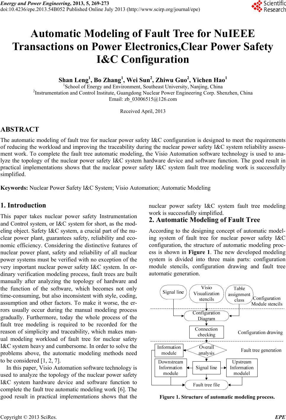 Energy and Power Engineering, 2013, 5, 269-273 doi:10.4236/epe.2013.54B052 Published Online July 2013 (http://www.scirp.org/journal/epe) Automatic Modeling of Fault Tree for NuIEEE Transactions on Power Electronics,Clear Power Safety I&C Configuration Shan Leng1, Bo Zhang1, We i Sun2, Zhiwu Guo2, Yichen Hao 1 1School of Energy and Environment, Southeast University, Nanjing, China 2Instrumentation and Control Institute, Guangdong Nuclear Power Engineering Corp. Shenzhen, China Email: [email protected] Received April, 2013 ABSTRACT The automatic modeling of fault tree for nuclear power safety I&C configuration is designed to meet the requirements of reducing the workload and improving the traceability during the nuclear power safety I&C system reliability assess- ment work. To complete the fault tree automatic modeling, the Visio Automation software technology is used to ana- lyze the topology of the nuclear power safety I&C system hardware device and software function. The good result in practical implementations shows that the nuclear power safety I&C system fault tree modeling work is successfully simplified. Keywords: Nuclear Power Safety I&C System; Visio Automation; Automatic Modeling 1. Introduction This paper takes nuclear power safety Instrumentation and Control system, or I&C system for short, as the mod- eling object. Safety I&C system, a crucial part of the nu- clear power plant, guarantees safety, reliability and eco- nomic efficiency. Considering the distinctive features of nuclear power plant, safety and reliability of all nuclear power systems must be verified with no exception of the very important nuclear power safety I&C system. In or- dinary verification modeling process, fault trees are built manually after analyzing the topology of hardware and the function of the software, which becomes not only time-consuming, but also inconsistent with style, coding, assumption and other factors. To make it worse, the er- rors usually occur during the manual modeling process gradually. Furthermore, today the whole process of the fault tree modeling is required to be recorded for the reason of simplicity and traceability, which makes man- ual modeling workload of fault tree for nuclear safety I&C system heavy and cumbersome. In order to solv e the problems above, the automatic modeling methods need to be conside red [1, 2, 7] . In this paper, Visio Automation software technology is used to analyze the topology of the nuclear power safety I&C system hardware device and software function to complete the fault tree automatic modeling work [6]. The good result in practical implementations shows that the nuclear power safety I&C system fault tree modeling work is successfully simplified. 2. Automatic Modeling of Fault Tree According to the designing concept of automatic model- ing system of fault tree for nuclear power safety I&C configuration, the structure of automatic modeling proc- ess is shown in Figure 1. The new developed modeling system is divided into three main parts: configuration module stencils, configuration drawing and fault tree automatic generation. Figure 1. Structure of automatic modeling process. Copyright © 2013 SciRes. EPE 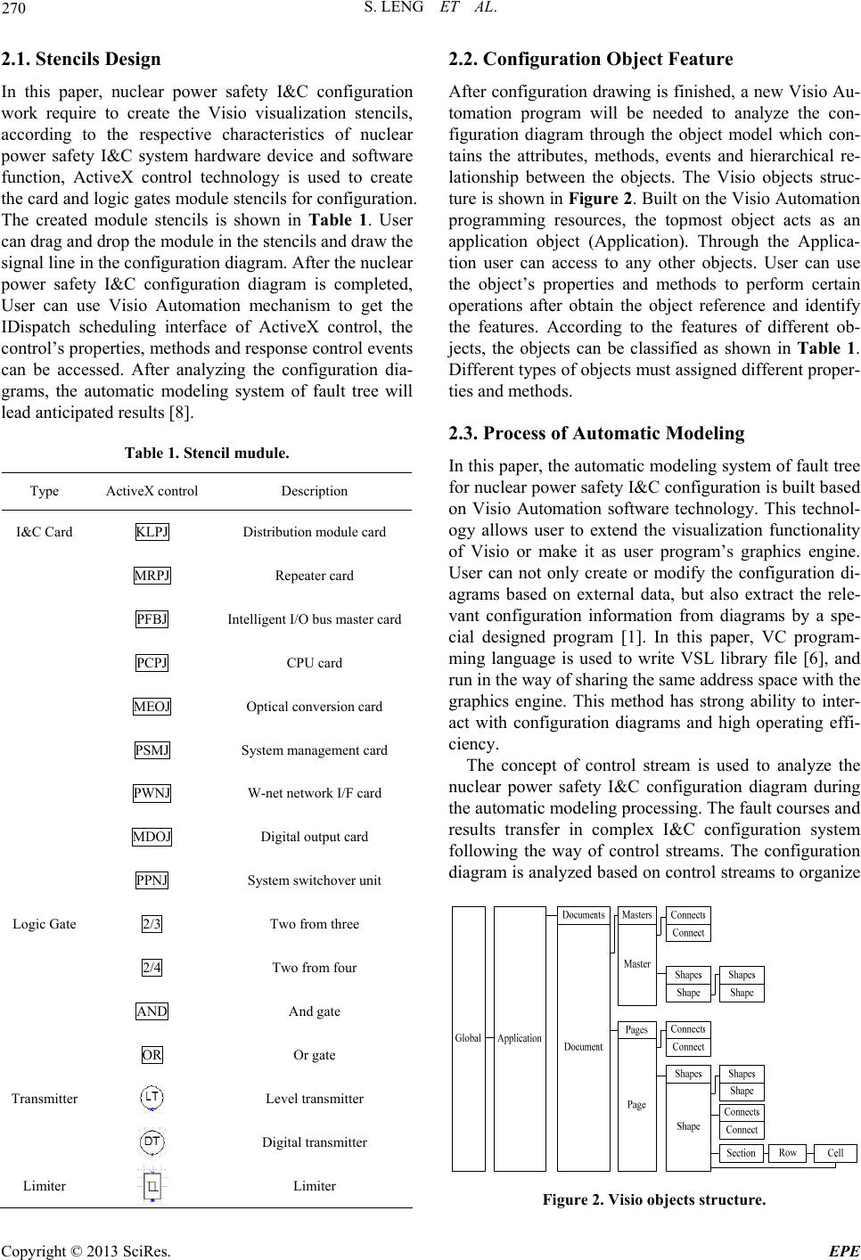 S. LENG ET AL. 270 2.1. Stencils Design In this paper, nuclear power safety I&C configuration work require to create the Visio visualization stencils, according to the respective characteristics of nuclear power safety I&C system hardware device and software function, ActiveX control technology is used to create the card and logic ga tes module stencils for configur ation. The created module stencils is shown in Table 1. User can drag and drop the module in the stencils and draw the signal line in the configuration diagram. After the nuclear power safety I&C configuration diagram is completed, User can use Visio Automation mechanism to get the IDispatch scheduling interface of ActiveX control, the control’s properties, methods and response control events can be accessed. After analyzing the configuration dia- grams, the automatic modeling system of fault tree will lead anticipated results [8]. Table 1. Stencil mudule. Type ActiveX control Description I&C Card KLPJ Distribution module card MRPJ Repeater card PFBJ Intelligent I/O bus master card PCPJ CPU card MEOJ Optical conversion card PSMJ System management card PWNJ W-net network I/F card MDOJ Digital output card PPNJ System switchove r unit Logic Gate 2/3 Two from three 2/4 Two from four AND And gate OR Or gate Transmitter Level transmitter Digital transmitter Limiter Limiter 2.2. Configuration Object Feature After configuration drawing is finished, a new Visio Au- tomation program will be needed to analyze the con- figuration diagram through the object model which con- tains the attributes, methods, events and hierarchical re- lationship between the objects. The Visio objects struc- ture is shown in Figure 2. Built on the Visio Automation programming resources, the topmost object acts as an application object (Application). Through the Applica- tion user can access to any other objects. User can use the object’s properties and methods to perform certain operations after obtain the object reference and identify the features. According to the features of different ob- jects, the objects can be classified as shown in Table 1. Different types of objects must assigned different proper- ties and methods. 2.3. Process of Automatic Modeling In this paper, the automatic modelin g system of fault tree for nuclear power safety I&C configuration is built b ased on Visio Automation software technology. This technol- ogy allows user to extend the visualization functionality of Visio or make it as user program’s graphics engine. User can not only create or modify the configuration di- agrams based on external data, but also extract the rele- vant configuration information from diagrams by a spe- cial designed program [1]. In this paper, VC program- ming language is used to write VSL library file [6], and run in the way of sharing the same address space with the graphics engine. This method has strong ability to inter- act with configuration diagrams and high operating effi- ciency. The concept of control stream is used to analyze the nuclear power safety I&C configuration diagram during the automatic modeling processing. The fault courses and results transfer in complex I&C configuration system following the way of control streams. The configuration diagram is analyzed based on control streams to organize Figure 2. Visio objects structure. Copyright © 2013 SciRes. EPE 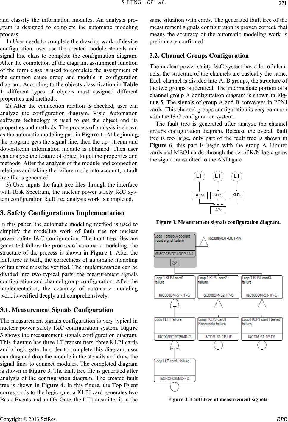 S. LENG ET AL. 271 and classify the information modules. An analysis pro- gram is designed to complete the automatic modeling process. 1) User needs to co mplete the drawing work of device configuration, user use the created module stencils and signal line class to complete the configuration diagram. After the completion of the diagram, assignment function of the form class is used to complete the assignment of the common cause group and module in configuration diagram. According to the objects classification in Table 1, different types of objects must assigned different properties and methods. 2) After the connection relation is checked, user can analyze the configuration diagram. Visio Automation software technology is used to get the object and its properties and methods. The process of analysis is shown as the automatic modeling part in Figure 1. At beginning, the program gets the signal line, then the up- stream and downstream information module is obtained. Then user can analyze the feature of object to get the properties and methods. After the analysis of the module and connection relations and taking the failure mode into accoun t, a fault tree file is generated. 3) User inputs the fault tree files through the interface with Risk Spectrum, the nuclear power safety I&C sys- tem configuration fault tree analysis work is completed. 3. Safety Configurations Implementation In this paper, the automatic modeling method is used to simplify the modeling work of fault tree for nuclear power safety I&C configuration. The fault tree files are generated follow the process of automatic modeling, the structure of the process is shown in Figure 1. After the fault tree is built, the correctness of automatic modeling of fault tree must be verified. The implementation can be divided into two typical parts: the measurement signals configuration and channel group configuration. After the implementation, the accuracy of automatic modeling work is verified deeply and comprehensively. 3.1. Measurement Signals Configuration The measurement signals configuration is very typical in nuclear power safety I&C configuration system. Figure 3 shows the measurement signals configuration diagram. This diagram has three LT transmitters, three KLPJ cards and a logic gate. In order to complete this diagram, user can drag and drop the module in the stencils and draw the signal lines to connect modules. The completed diagram is shown in Figure 3. The fault tree file is generated after analysis of the configuration diagram. The created fault tree is shown in Figure 4. In this figure, the Top Event corresponds to the logic gate, a KLPJ card generates two Basic Events and an OR Gate, the LT transmitter is in the same situation with cards. The generated fault tree of the measurement signals configuration is proven correct, that means the accuracy of the automatic modeling work is preliminary confirmed. 3.2. Channel Groups Configuration The nuclear power safety I&C system has a lot of chan- nels, the structur e of the channels are b asically the same. Each channel is divided into A, B groups, the structure of the two groups is identical. Th e intermediate portion of a channel group A configuration diagram is shown in Fig- ure 5. The signals of group A and B converges in PPNJ cards. This channel groups configuration is very common with the I&C configuration system. The fault tree is generated after analyze the channel groups configuration diagram. Because the overall fault tree is too large, only part of the fault tree is shown in Figure 6, this part is begin with the group A Limiter cards and MEOJ cards ,through the set of K/N logic gates the signal transmitted to the AND gate. LT LT LT KLPJ KLPJ KLPJ 2/3 Figure 3. Measurement signals configuration diagram. Figure 4. Fault tree of measurement signals. Copyright © 2013 SciRes. EPE 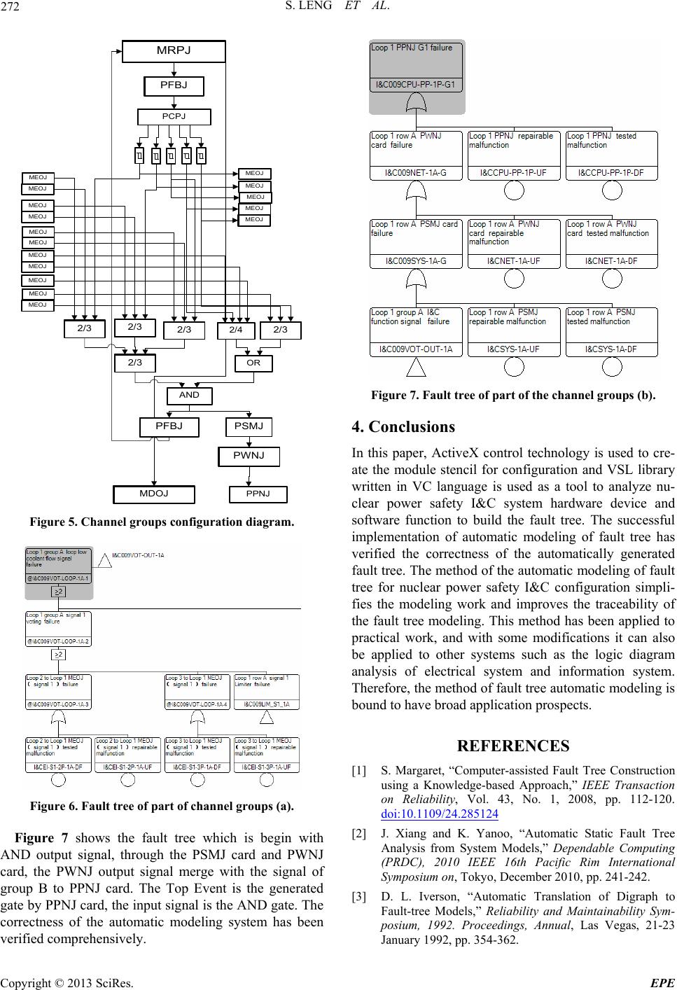 S. LENG ET AL. 272 OR 2/3 2/3 2/3 2/3 2/3 MRPJ PFBJ PCPJ MEOJ MEOJ MEOJ MEOJ MEOJ MEOJ MEOJ MEOJ MEOJ MEOJ MEOJ MEOJ MEOJ MEOJ MEOJ 2/4 AND PFBJ PWNJ MDOJ PPNJ PSMJ MEOJ Figure 5. Channel groups configuration diagram. Figure 6. Fault tree of part of channel groups (a). Figure 7 shows the fault tree which is begin with AND output signal, through the PSMJ card and PWNJ card, the PWNJ output signal merge with the signal of group B to PPNJ card. The Top Event is the generated gate by PPNJ card, the input signal is the AND gate. The correctness of the automatic modeling system has been verified comprehensively. Figure 7. Fault tree of part of the channel groups (b). 4. Conclusions In this paper, ActiveX control technology is used to cre- ate the module stencil for configuration and VSL library written in VC language is used as a tool to analyze nu- clear power safety I&C system hardware device and software function to build the fault tree. The successful implementation of automatic modeling of fault tree has verified the correctness of the automatically generated fault tree. The method of the automatic modeling of fault tree for nuclear power safety I&C configuration simpli- fies the modeling work and improves the traceability of the fault tree modeling. This method has been applied to practical work, and with some modifications it can also be applied to other systems such as the logic diagram analysis of electrical system and information system. Therefore, the method of fault tree au tomatic modeling is bound to have broad application prospects. REFERENCES [1] S. Margaret, “Computer-assisted Fault Tree Construction using a Knowledge-based Approach,” IEEE Transaction on Reliability, Vol. 43, No. 1, 2008, pp. 112-120. doi:10.1109/24.285124 [2] J. Xiang and K. Yanoo, “Automatic Static Fault Tree Analysis from System Models,” Dependable Computing (PRDC), 2010 IEEE 16th Pacific Rim International Symposium on, Tokyo, December 2010, pp. 241-242. [3] D. L. Iverson, “Automatic Translation of Digraph to Fault-tree Models,” Reliability and Maintainability Sym- posium, 1992. Proceedings, Annual, Las Vegas, 21-23 January 1992, pp. 354-362. Copyright © 2013 SciRes. EPE  S. LENG ET AL. Copyright © 2013 SciRes. EPE 273 [4] J. Xiang, K. Yanoo, Y. Maeno and K. Tadano, “Autmatic Synthesis of Static Fault Trees from System Models,” Secure Software Integration and Reliability Improvement (SSIRI), 2011 Fifth International Conference on, Jeju Is- land, 27-29 June 2011, pp. 127-136. [5] A. Madni, “The Role of Human Factors in Expert Sys- tems Design and Acceptance,” Human Factors: The Journal of the Human Factors and Ergonomics Society, Vol. 30, No. 4,1988, pp. 395-414. [6] Q. Liu, X. J. Liu and X. B. Ma, “Analysis of Logic Graph Based on Visio Automation,” Software Guide, Vol. 8, No. 1, 2009, pp. 13-15. [7] B. Han, J. J. Tong and D. Z. Xue,” Fault Tree Com- puter-Aided Building Expert System,” Nuclear Power Engineering, Vol. 24, No. 1, 2003, pp. 77-79 [8] H. CH. Shi and Y. Wang, “Expert System for Fault Di- agnosis in a Sewage-disposal Factory,” Feedwater and Drainage, Vol. 27, No. 8,2007,pp. 56-60 |