

Paper Menu >>
Journal Menu >>
 Energy and Power Engineering, 2013, 5, 264-268 doi:10.4236/epe.2013.54B051 Published Online July 2013 (http://www.scirp.org/journal/epe) Fault Tree Reliability Analysis for Passive Medium Pressure Safety Injection System in Nuclear Power Plant Lengshan Leng, Yun Liu School of Energy and Environment, Southeast University, Nanjing, China Email: [email protected] Received April, 2013 ABSTRACT Modern nuclear power plants, both newly designed generation 3 and existing generation 2 reactors, make use of passive safety systems for significant and measurable improvements in safety and reliability. Medium Pressure Safety Injection System (MP-SIS) in Tianwan Nuclear Power Plant is a typical and very important nuclear safety passive system. This paper discusses the reliability of MP-SIS on the basis of Fault Tree Analysis (FTA) with unavailability and Minimal Cut Set (MCS) calculated as two important indicators. The result illustrates that the passive MP-Safety Injection Tank barely contributes to the system’s unavailability and human interactions with Manual Valves and Motor Operated Valves have great negative impact on the reliability. Keywords: Passive Safety System; MP-SIS; FTA; Unavailability; MCS 1. Introduction The experts of nuclear power industry conclude that the Passive Safety System makes related safety functions less dependent on operator and that external energy sup- ply is potentially more reliable than active system. Be- cause of its simplicity, reduced human interaction and hardware failure [1, 2], Passive Safety System has been mainly designed in the new generation 3 nuclear power plant under construction. Nevertheless, Passive Safety System is also installed in the existing generation 2 nu- clear power plant in use. Tianwan Nuclear Power Plant, the two 1000MW PWRs (Pressurized Water Reactors) generation 2+ nuclear power plant in China, is equipped with High, Medium and Low pressure safety injection systems separately to ensure that injecting of boric acid will co ol an d sub merge the reactor core when the average temperature and pres- sure of primary loop reduce, a phenomenon caused by a LOCA (Loss Of Coolant Accident) in primary loop or a MSLB (Main Steam Line Break) in secondary loop. The Medium Pressure Safety Injection System (MP-SIS) in- stalled inside is a typical passive safety system. Without any active pump, the system is put into operation when pressure difference between safety injection tank and core reaches below certain value during the accident. From this perspective, the passive MP-SIS safety as- sessment and reliability analysis becomes necessary and important both for operation of existing plant and design of new gen era tion nucl e ar power pla nt . The present paper aims to adopt the FTA (Fault Tree Analysis) reliability analysis method [2] to build a FT (Fault Tree) with MP-SIS failure as the Top Event so as to obtain its unavailability and MCSs. The quantitative calculation is made according to commonly estimated and accepted data due to the fact that some of the possi- bility data in this paper haven’t been released before [3, 4]. 2. Description of MP-SIS The medium pressure safety injection system, MP-SIS (tag named JNG-2) in the 1000 MW PWR nuclear power plant operates when the primary loop leaks and the cool- ant pressure drops to 5.9 MPa. The MP-SIS injects water with boric acid of 16 g/kg into the primary loop to con- trol the core into a sub-critical state and make it cooled down. The system consists of four series (Series JNG50, JNG60, JNG70, and JNG80) which are independent and physic-cally isolated from each other. Each series in- cludes the following components and pipelines [5]. The Pipe and Instrumentation Diagram (P&ID) of Series JNG50 is shown in Figure 1. MP-Safety Injection Tank: Reception and storage of boric acid solution. Safety Valves Groups: Prevent Injection Tank from overpressure. Nitrogen Inflation Pipeline: Inflating nitrogen gas from High-pressure Nitrogen System (tag named KRJ) to Injection Tank. Copyright © 2013 SciRes. EPE 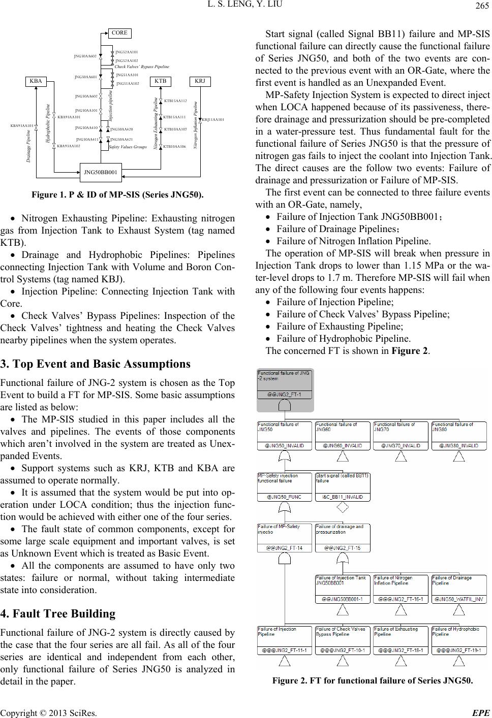 L. S. LENG, Y. LIU 265 JNG50AA602 JNG50AA601 JNG52AA101 JNG52AA102 JNG51AA101 JNG51AA102 KBA93AA103 JNG50BB001 KBA KBA93AA101 KBA93AA102 JNG50AA101 JNG50AA602 KTB15AA111 KTB15AA112 KTB10AA106 KTB10AA107 KTB KRJ11AA103 JNG50AA410 JNG50AA411 Safety Values Groups JNG50AA420 JNG50AA421 CORE Check Valves’ Bypass Pipeline KRJ Figure 1. P & ID of MP-SIS (Series JNG50). Nitrogen Exhausting Pipeline: Exhausting nitrogen gas from Injection Tank to Exhaust System (tag named KTB). Drainage and Hydrophobic Pipelines: Pipelines connecting Injection Tank with Volume and Boron Con- trol Systems (tag named KBJ). Injection Pipeline: Connecting Injection Tank with Core. Check Valves’ Bypass Pipelines: Inspection of the Check Valves’ tightness and heating the Check Valves nearby pipelines when the system operates. 3. Top Event and Basic Assumptions Functional failure of JNG-2 system is chosen as the Top Event to build a FT for MP-SIS. Some ba sic assumptions are listed as below: The MP-SIS studied in this paper includes all the valves and pipelines. The events of those components which aren’t involved in the system are treated as Unex- panded Events. Support systems such as KRJ, KTB and KBA are assumed to operate normally. It is assumed that the system would be put into op- eration under LOCA condition; thus the injection func- tion would be achi e ve d wi t h ei t her one of t h e fou r seri es. The fault state of common components, except for some large scale equipment and important valves, is set as Unknown Event which is treated as Basic Event. All the components are assumed to have only two states: failure or normal, without taking intermediate state into consideration . 4. Fault Tree Building Functional failure of JNG-2 system is directly caused by the case that the four series are all fail. As all of the four series are identical and independent from each other, only functional failure of Series JNG50 is analyzed in detail in the pape r. Start signal (called Signal BB11) failure and MP-SIS functional failure can directly cause the functional failure of Series JNG50, and both of the two events are con- nected to the previous event with an OR-Gate, where the first event is handled as an Unexpanded Event. MP-Safety Injection System is expected to direct inject when LOCA happened because of its passiveness, there- fore drainag e and pressuri zation should b e pre-completed in a water-pressure test. Thus fundamental fault for the functional failure of Series JNG50 is that the pressure of nitrogen gas fails to in ject the co olan t into Injectio n Tank. The direct causes are the follow two events: Failure of drainage and pressurization or Failure of MP-SIS. The first event can be connected to three failure events with an OR-Gate, namely, Failure of Injection Tank JNG50BB001; Failure of Drainage Pipelines; Failure of Nitrogen Inflation Pipeline. The operation of MP-SIS will break when pressure in Injection Tank drops to lower than 1.15 MPa or the wa- ter-level drops to 1.7 m. Therefore MP-SIS will fail when any of the following four events happens: Failure of Injection Pipeline; Failure of C heck Valves’ Bypass P ipeline; Failure of Exhausting Pipeline; Failure of Hydrophobic Pipeline. The concerned FT is shown in F igure 2. Figure 2. FT for functional failure of Series JNG50. Copyright © 2013 SciRes. EPE 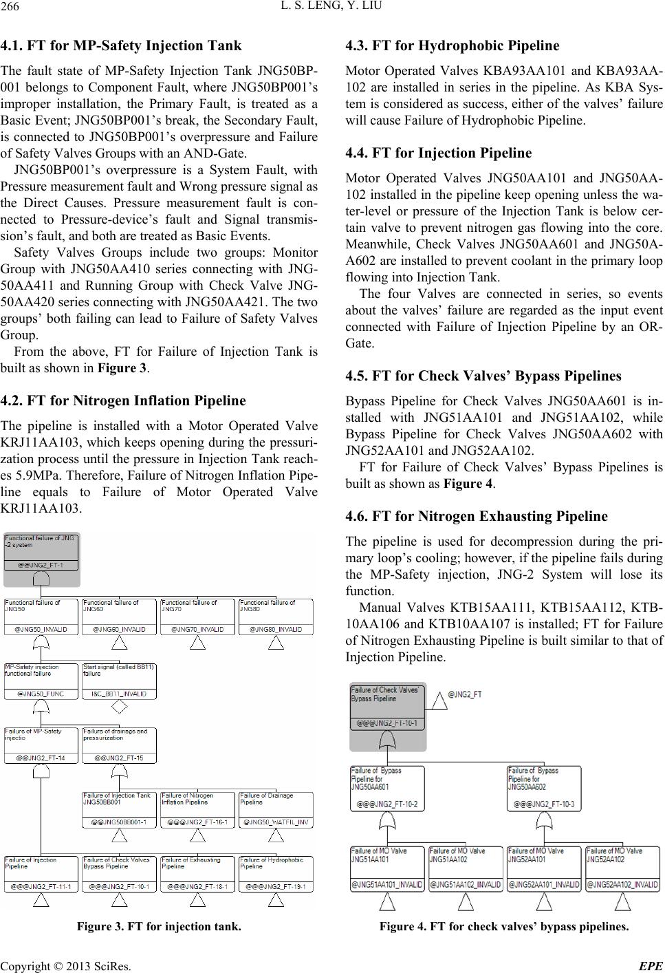 L. S. LENG, Y. LIU 266 4.1. FT for MP-Safety Injection Tank The fault state of MP-Safety Injection Tank JNG50BP- 001 belongs to Component Fault, where JNG50BP001’s improper installation, the Primary Fault, is treated as a Basic Event; JNG50BP001’s break, the Secondary Fault, is connected to JNG50BP001’s overpressure and Failure of Safety Valves Groups with an AND-Gate. JNG50BP001’s overpressure is a System Fault, with Pressure measurement fault and Wrong pressure signal as the Direct Causes. Pressure measurement fault is con- nected to Pressure-device’s fault and Signal transmis- sion’s fault, and both are treated as Basic Events. Safety Valves Groups include two groups: Monitor Group with JNG50AA410 series connecting with JNG- 50AA411 and Running Group with Check Valve JNG- 50AA420 series conn ecting with JNG50AA42 1. The two groups’ both failing can lead to Failure of Safety Valves Group. From the above, FT for Failure of Injection Tank is built as shown in Figure 3. 4.2. FT for Nitrogen Inflation Pipeline The pipeline is installed with a Motor Operated Valve KRJ11AA103, which keeps opening during the pressuri- zation process until the pressure in Injection Tank reach- es 5.9MPa. Therefore, Failure of Nitrogen Inflation Pipe- line equals to Failure of Motor Operated Valve KRJ11AA103. Figure 3. FT for injection tank. 4.3. FT for Hydrophobic Pipeline Motor Operated Valves KBA93AA101 and KBA93AA- 102 are installed in series in the pipeline. As KBA Sys- tem is considered as success, either of the valves’ failure will cause Failure of Hydrophobic Pipeline. 4.4. FT for Injection Pipeline Motor Operated Valves JNG50AA101 and JNG50AA- 102 installed in the pipelin e keep opening unless the wa- ter-level or pressure of the Injection Tank is below cer- tain valve to prevent nitrogen gas flowing into the core. Meanwhile, Check Valves JNG50AA601 and JNG50A- A602 are installed to preven t coolant in the primary loop flowing into Injection Tan k. The four Valves are connected in series, so events about the valves’ failure are regarded as the input event connected with Failure of Injection Pipeline by an OR- Gate. 4.5. FT for Check Valves’ Bypass Pipelines Bypass Pipeline for Check Valves JNG50AA601 is in- stalled with JNG51AA101 and JNG51AA102, while Bypass Pipeline for Check Valves JNG50AA602 with JNG52AA101 and JNG52AA102. FT for Failure of Check Valves’ Bypass Pipelines is built as shown as Figure 4. 4.6. FT for Nitrogen Exhausting Pipeline The pipeline is used for decompression during the pri- mary loop’s cooling ; however, if the pipeline fails during the MP-Safety injection, JNG-2 System will lose its function. Manual Valves KTB15AA111, KTB15AA112, KTB- 10AA106 and KTB10AA107 is installed; FT for Failure of Nitrogen Exhausting Pipeline is built similar to that of Injection Pipeline. Figure 4. FT for check valve s’ bypass pipelines. Copyright © 2013 SciRes. EPE 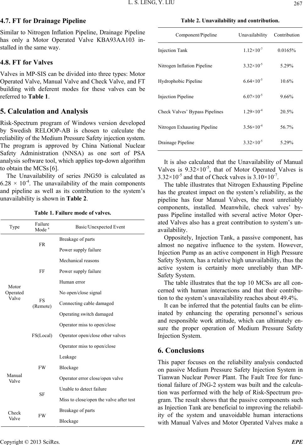 L. S. LENG, Y. LIU 267 4.7. FT for Drainage Pipeline Similar to Nitrogen Inflation Pipeline, Drainage Pipeline has only a Motor Operated Valve KBA93AA103 in- stalled in the same way. 4.8. FT for Valves Valves in MP-SIS can be divided into three types: Motor Operated Valve, Manual Valve and Check Valve, and FT building with deferent modes for these valves can be referred to Table 1. 5. Calculation and Analysis Risk-Spectrum program of Windows version developed by Swedish RELOOP-AB is chosen to calculate the reliability of the Medium Pres sure Safety injection system. The program is approved by China National Nuclear Safety Administration (NNSA) as one sort of PSA analysis software tool, which applies top-down algorithm to obtain the MCSs [6]. The Unavailability of series JNG50 is calculated as 6.28 × 10⁻⁴. The unavailability of the main components and pipeline as well as its contribution to the system’s unavailability is shown in Table 2. Table 1. Failure mode of valves. Type Failure Mode a Basic/Unexpected Event Breakage of parts FR Power supply failure Mechanical reasons Power supply failure FF Human error No open/close signal Connecting cable damaged FS (Remote) Operating switch damaged Operator miss to open/close Operator open/close other valves Motor Operated Valve FS(Local) Operator miss to open/close Leakage Blockage FW Operator error close/open valve Unable to detect failure Manual Valve SF Miss to close/open the valve after test Breakage of parts Check Valve FW Blockage Table 2. Unavailability and contribution. Component/Pipeline Unavailability Contribution Injection Tank 1.12×10⁻⁷ 0.0165% Nitrogen Inflation Pipeline 3.32×10⁻⁵ 5.29% Hydrophobic Pipeline 6.64×10⁻⁵ 10.6% Injection Pipeline 6.07×10⁻⁵ 9.66% Check Valves’ Bypass Pipelines 1.29×10⁻⁴ 20.5% Nitrogen Exhausting Pipeline 3.56×10⁻⁴ 56.7% Drainage Pipeline 3.32×10⁻⁵ 5.29% It is also calculated that the Unavailability of Manual Valves is 9.32×10⁻⁵, that of Motor Operated Valves is 3.32×10⁻⁵ and that of Check valves is 3.10×10⁻⁷. The table illustrates that Nitrogen Exhausting Pipeline has the greatest impact on the system’s reliability, as the pipeline has four Manual Valves, the most unreliably components, installed. Meanwhile, check valves’ by- pass Pipeline installed with several active Motor Oper- ated Valves also has a great contribution to system’s un- availability. Oppositely, Injection Tank, a passive component, has almost no negative influence to the system. However, Injection Pump as an active component in High Pressure Safety System, has a relative high unavailability, th us the active system is certainly more unreliably than MP- Safety System. The table illustrates that the top 10 MCSs are all con- cerned with human interactions and that their contribu- tion to the system’s unavailability reaches about 49.4%. It can be inferred that the potential faults can be elim- inated by enhancing the operating personnel’s serious and responsible work attitude, which can ultimately en- sure the proper operation of Medium Pressure Safety Injection System. 6. Conclusions This paper focuses on the reliability analysis conducted on passive Medium Pressure Safety Injection System in Tianwan Nuclear Power Plant. The Fault Tree for func- tional failure of JNG-2 system was built and the calcula- tion was performed with the help of Risk-Spectrum pro- gram. The result shows that the passive components such as Injection Tank are ben eficial to improving the reliabil- ity of the system and unavoidable human interactions with Manual Valves and Motor Operated Valves make a Copyright © 2013 SciRes. EPE  L. S. LENG, Y. LIU Copyright © 2013 SciRes. EPE 268 great contribution to the system’s unavailability. REFERENCES [1] E. Zio and N. Pedroni, “Monte Carlo Simulation-based Sensitivity Analysis of the Model of a Thermal-hydraulic Passive System,” Reliability Engineering and System Safety, Vol. 107, 2012, pp. 90-106. doi:10.1016/j.ress.2011.08.006 [2] A. K. Nayak, M. R. Gartia, A. Antony, G. Vinod and R. K. Sinha, “Passive System Reliability Analysis Using the APSRA Methodology,” Nuclear Engineering and Design, Vol. 238, No. 6, 2008, pp. 1430-1440. doi:10.1016/j.nucengdes.2007.11.005 [3] USURC, “NUREG-75/014. WASH-1400”, 1975. [4] NNSA, “Probabilistic Safety Assessment Report Prob- abilistic Safety Assessment (PSA) Qinshan CANDU Pro- ject,12. 98-03600-PSA-001,” 2003. [5] G. Y. Jiang, “WWER-1000 Nuclear Power Plant Equip- ment and System,” 1st Edition, Atomic Energy Press, 2009. [6] A. B. Relcon, “Risk Spectrum Theory Manual,” 1998. |