

Paper Menu >>
Journal Menu >>
 Energy and Power E ngineering, 2013, 5, 209-214 doi:10.4236/epe.2013.54B041 Published Online July 2013 (http://www.scirp .o rg/journal/epe) Copyright © 2013 SciRes. EPE Accommodating High PV Penetration on the Distribution System of Kinmen Island Yuan-Kang Wu1, Shao-Hong Tsai2, Ming-Yan Zou1 1Department of Electrical Engineering, National Chung-Cheng University 2Department of Electrical Engineering, Hwa Hsia Institute of Technology Email: [email protected], [email protected] Received February, 2013 ABSTRACT A lar ge-scale PV installation has a profound effect on the p ower quality and operation of the grid. Therefore, as instal- lations of PV systems increase, changes to both technologies and interconnectio n standards are needed to address these high PV pe netrat ion systems. This paper investigates the main technical i mpacts of large-scale PV generations on power grids and associated interconnection standards. A case study b y us ing t he PSS /E so ftware in the Kinme n po wer syst em was impleme nted to study the steady-state and transient char a c te r istics for the high penetr ation PV systems. Keywords: PV; Penetra tion; Interconnectio n S tandard; PSS/E; Kinmen 1. Introduction There is an increasing introduction of renewable energy generation into po wer grids, like wind power and photo- voltaic (PV) generations, which causes control and oper- ation problems to the utilities since the net wor ks have not been pre-designed to take into account these distributed or intermittent generations. The electricity from PV is difficult to predict and mainly dependent on weather conditions. Furthermore, they are usually connected to grid through power electronic converter, and this also presents a significant difference from conventional ge- nerators. As the penetration of the solar PV plant in- creases, its impact on the stability and operation of the grid needs to be well understood. Because of the inter- mittency of the output from solar plants, these impacts might be significant, especially when the solar irradiance drops from 100% to 20% in a minute, causing numerous problems in a high penetration scenario. Additionally, since traditional feeders are commonly designed for radi- al unid irectional power flows, it is expected that some of the most significant impacts occur for large PV penetra- tion levels. The main technical impacts of large scale PV genera- tions on power grid are: voltage, current profiles, power quality, protection, electric losses, power factor, power balancing, reliability, protection and operability of the system. Solar PV generation impacts can be of steady state or dynamic in nature. These impacts vary in severi- ty as a function of the degree o f penetration and location of solar PV distributed gene rat ion. Fo r inst ance, PV ge n- eration is genera lly at its optimal arou nd moon, and ge n- erally this is a period of light load condition; therefore, power export through the distribution feeder and the substation back to the system becomes possible. The as- sociated r everse po wer flow will te nd to ra ise the volta ge on the distribution feeder. Additionally, introducing PV at the load side would reduce the load demand and in turn leads to reduced losses and improved voltage pro- files on the feeder. This is an important benefit from a capacity planning perspective since it allows utilities to defer capital investments. Typical system integration problems in large PV sys- tems include [1]: no dispatch capability of PV solar farms without storage, ultra-fast ramping requirements (400 – 1000 MW/min), reactive power management of feeders are not designed with high PV production, power quality, especially voltage fluctuations, flicker and har- monics may be out of IEEE-519 and other standards. Several research works [2] indicate that the impact is lower in the case of distributed PVs compared to concen- trated PVs with the same penetration level, and a larger grid with slow-response generators experiences larger variations in system. In the USA, the department of energy (DOE) solar energy conducted a competitive Funding Opportunity Announcement, and six competitively selected projects have been completed [3]. For example, several projects used actual distribution feeders as the basis for model development and testing high PV penetration; according to the research results, PV inverter capabilities may be useful in mitigating system impacts. Intelligent inverters are expected to p rovide significant benefit to fut ure elec- 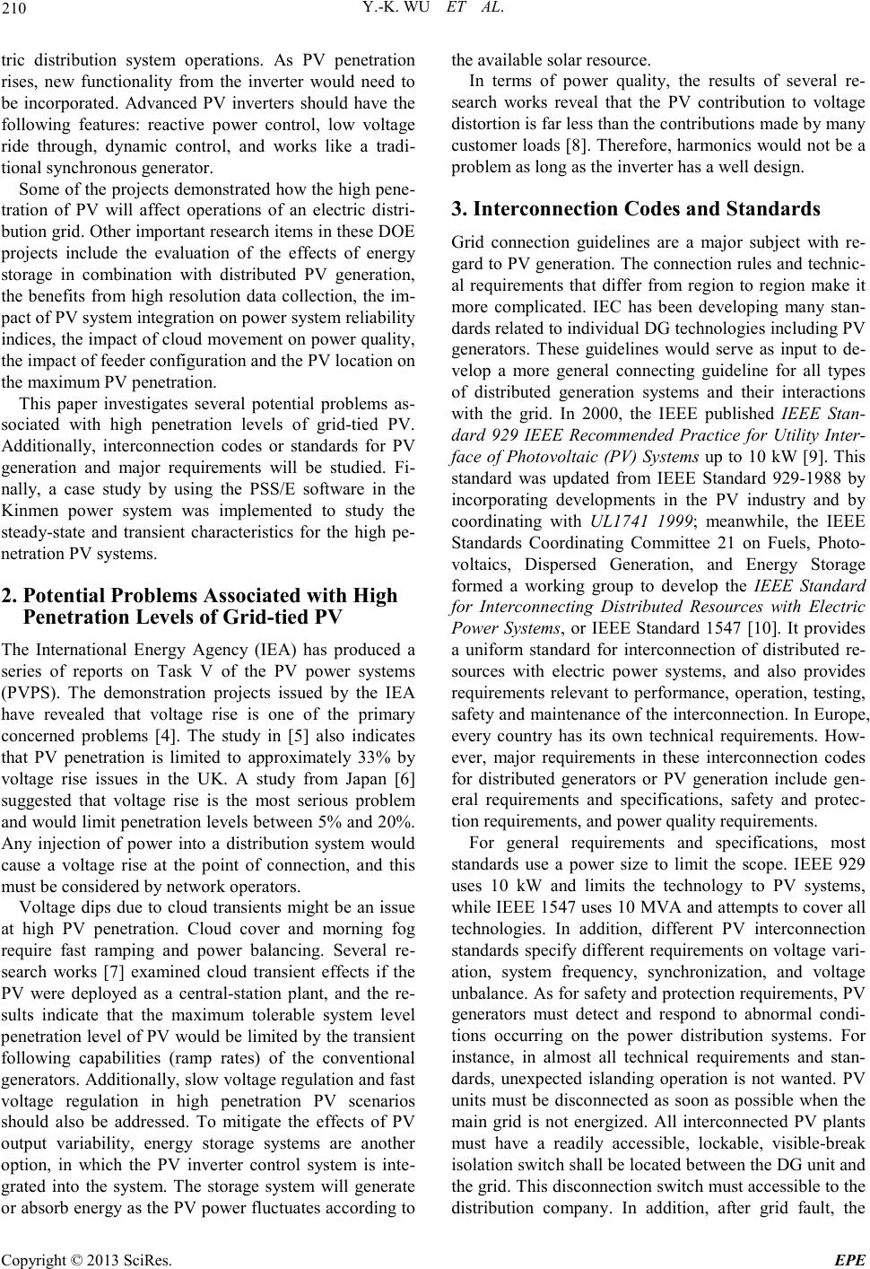 Y.-K. WU ET AL. Copyright © 2013 SciRes. EPE 210 tric distribution system operations. As PV penetration rises, new functionality from the inverter would need to be incorporated. Advanced PV inverters should have the following features: reactive power control, low voltage ride through, dynamic control, and works like a tradi- tional synchro nous generator . Some of the projects demonstrated how the high pene- tration of PV will affect operations of an electric distri- butio n gr id . O the r i mpo r tant re sea r ch it e ms i n t he se DOE projects include the evaluation of the effects of energy storage in combination with distributed PV generation, the benefits from high resolution data collection, the im- pact of PV system integra tion on p ower syste m relia bility indices, the impact of cloud movement on power quality, the impact of feeder configuration and the PV location on the maximum PV penetration. This paper investigates several potential problems as- sociated with high penetration levels of grid-tied PV. Additionally, interconnection codes or standards for PV generation and major requirements will be studied. Fi- nally, a case study by using the PSS/E software in the Kinmen power system was implemented to study the steady-state and transient characteristics for the high pe- netration PV systems. 2. Potential Problems Associated with High Penetration Levels of Grid-tied PV The International Energy Agency (IEA) has produced a series of reports on Task V of the PV power systems (PVPS). The demonstration projects issued by the IEA have revealed that voltage rise is one of the primary concerned problems [4]. The study in [5] also indicates that PV penetration is limited to approximately 33% by voltage rise issues in the UK. A study from Japan [6] suggested that voltage rise is the most serious problem and would limit penetration levels between 5% and 20%. Any injection of power into a distribution system would cause a voltage rise at the point of connection, and this must be considered by network operators. Voltage dips due to cloud transients might be an issue at high PV penetration. Cloud cover and morning fog require fast ramping and power balancing. Several re- search works [7] examined cloud transient effects if the PV were deployed as a central-station plant, and the re- sults indicate that the maximum tolerable system level penetration le vel of PV wo uld be limited by the tra nsient following capabilities (ramp rates) of the conventional generators. Additionall y, slo w volta ge reg ulatio n a nd fast voltage regulation in high penetration PV scenarios should also be addressed. To mitigate the effects of PV output variability, energy storage systems are another option, in which the PV inverter control system is inte- grated into the system. The storage system will generate or absorb energy as the PV power fluctuates according to the available solar resource. In terms of power quality, the results of several re- search works reveal that the PV contribution to voltage distortion is far les s than t he c ontributio ns made b y many customer loads [8]. Therefore, harmonics would not be a problem as long as the inverter has a well design. 3. Interconnection Codes and Standards Grid connection guidelines are a major subject with re- gard to PV gene rat ion. The connection rules and technic- al requirements that differ from region to region make it more complicated. IEC has been developing many stan- dards re lated to individual DG te chnologie s includi ng P V generators. These guidelines would serve as input to de- velop a more general connecting guideline for all types of distributed generation systems and their interactions with the grid. In 2000, the IEEE published IEEE Stan- dard 929 IEEE Recommended Practice for Utility Inter- face of Photovoltaic (PV) Systems up to 10 kW [9]. Thi s standard was updated from IEEE Standard 929-1988 by incorporating developments in the PV industry and by coordinating with UL1741 1999; meanwhile, the IEEE Standards Coordinating Committee 21 on Fuels, Photo- voltaics, Dispersed Generation, and Energy Storage formed a working group to develop the IEEE Standard for Interconnecting Distributed Resources with Electric Power Systems, or IEEE Standard 1547 [10]. It provides a uniform standard for interconnection of distributed re- sources with electric power systems, and also provides requirements relevant to performance, operation, testing, safety and maintenance of the interconnection. In Europe, every country has its own technical requirements. How- ever, major requirements in these interconnection codes for distributed generators or PV generation include gen- eral requirements and specifications, safety and protec- tion requirements, and power quality requirements. For general requirements and specifications, most standards use a power size to limit the scope. IEEE 929 uses 10 kW and limits the technology to PV systems, while IEEE 1547 uses 10 MVA and attempts to cover all technologies. In addition, different PV interconnection standards specify different requirements on voltage vari- ation, system frequency, synchronization, and voltage unbalance. As fo r safety and protection requirements, PV generators must detect and respond to abnormal condi- tions occurring on the power distribution systems. For instance, in almost all technical requirements and stan- dards, unexpected islanding operation is not wanted. PV units must be disconnected as soon as possible when the mai n grid is not energized. All interconnected PV plants must have a readily accessible, lockable, visible-break isolation switch s hall be located between the DG unit and the gri d. T hi s d isconnectio n switc h must ac cessible to the distribution co mpany. In addition, after grid fault, the 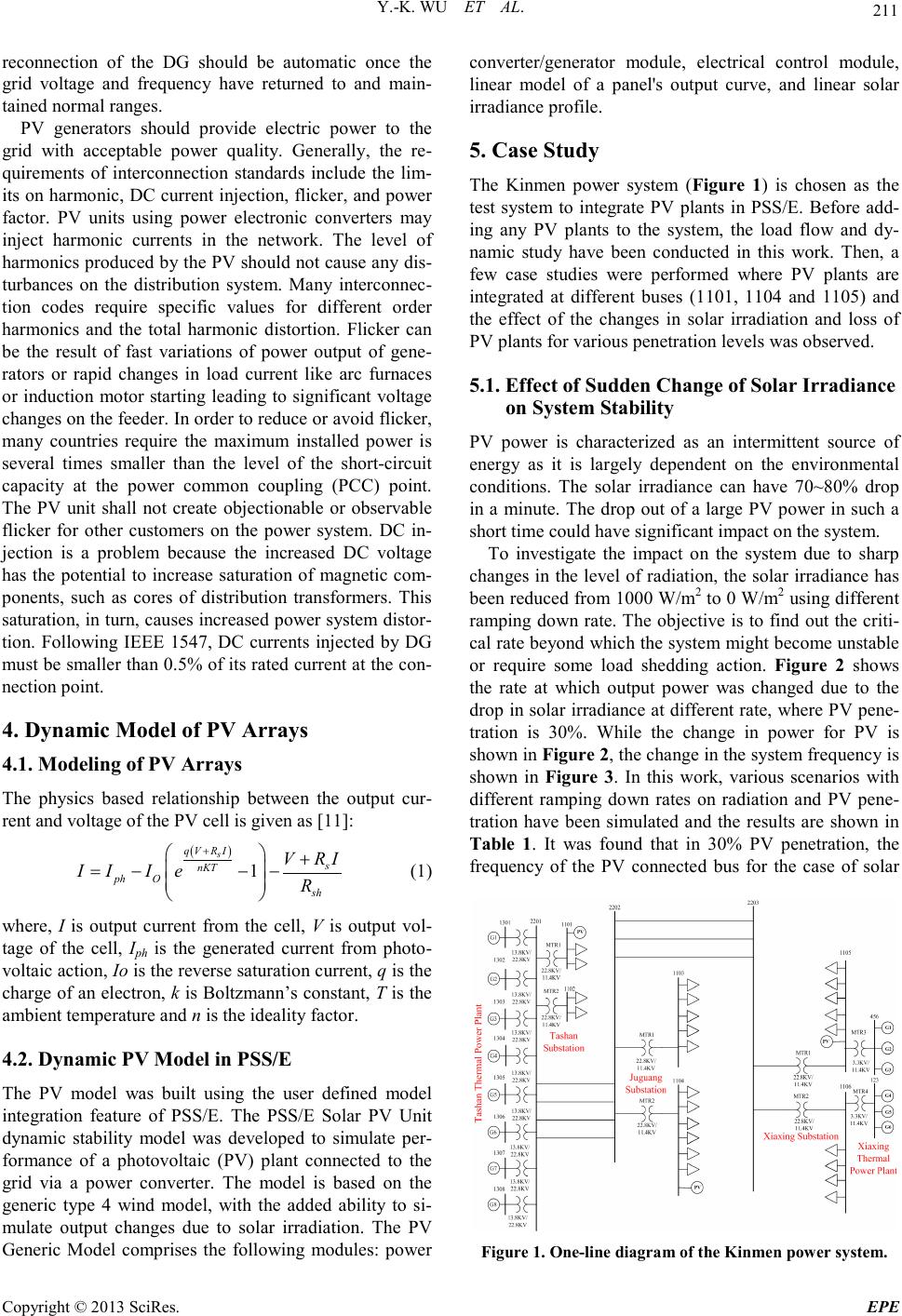 Y.-K. WU ET AL. Copyright © 2013 SciRes. EPE 211 reconnection of the DG should be automatic once the grid voltage and frequency have returned to and main- taine d normal r anges. PV generators should provide electric power to the grid with acceptable power quality. Generally, the re- quirements of interconnection standards include the lim- its on ha rmonic, DC current injectio n, flicker, and power factor. PV units using power electronic converters may inject harmonic currents in the network. The level of harmonics produced by the PV sho uld not cause a ny dis - turbances on the distribution system. Many interconnec- tion codes require specific values for different order harmonics and the total harmonic distortion. Flicker can be the result of fast variations of power output of gene- rators or rapid changes in load current like arc furnaces or induction motor starting leading to significant voltage changes on the feeder. In order to reduce or avoid flicker, many countries require the maximum installed power is several times smaller than the level of the short-circuit capacity at the power common coupling (PCC) point. The PV unit shall not create objectionable or observable flicker for other customers on the power system. DC in- jection is a problem because the increased DC voltage has the potential to increase saturation of magnetic com- ponents, such as cores of distribution transformers. This saturation, in turn, causes increased power system distor- tion. Following IEEE 1547, DC currents injected by DG must be smaller tha n 0.5% of its rated current at the con- necti on po int. 4. Dynamic Model of PV Arrays 4.1. Modeling of PV Arrays The physics based relationship between the output cur- rent and vol tage of the PV cell is given as [11]: ( ) 1 s qV RI s nKT ph Osh V RI II IeR + + =−− − (1) where, I is output current from the cell, V is output vol- tage of the cell, Iph is the generated current from photo- voltaic actio n, Io is the reverse saturation current, q is the charge of an electron, k is B oltzmann’s con stant, T is the ambient temper a ture and n is the ideality factor. 4.2. Dynamic PV Model in PSS/E The PV model was built using the user defined model integration feature of PSS/E. The PSS/E Solar PV Unit dynamic stability model was developed to simulate per- formance of a photovoltaic (PV) plant connected to the grid via a power converter. The model is based on the generic type 4 wind model, with the added ability to si- mulate output changes due to solar irradiation. The PV Generic Model comprises the following modules: power converter/generator module, electrical control module, linear model of a panel's output curve, and linear solar irradiance profile. 5. Case Study The Kinmen power system (Figure 1) is chosen as the test system to integrate PV plants in PSS/E. Before add- ing any PV plants to the system, the load flow and dy- namic study have been conducted in this work. Then, a few case studies were performed where PV plants are integrated at different buses (1101, 1104 and 1105) and the effect of the changes in solar irradiation and loss of PV plants for various penetration levels was observed. 5.1. Effect of Sudden Change of Solar Irradiance on System Stability PV power is characterized as an intermittent source of energy as it is largely dependent on the environmental conditions. The solar irradiance can have 70~80% drop in a minute. The drop out of a large PV power in such a short time could have significant i mpact on the system. To investigate the impact on the system due to sharp changes in the level of radiation, the solar irradiance has been reduced from 1000 W/m2 to 0 W /m2 using different ramping down rate. The objective is to find out the criti- cal rate beyond which the system might become unstable or require some load shedding action. Figure 2 shows the rate at which output power was changed due to the drop in solar irradiance at different rate, where PV pene- tration is 30%. While the change in power for PV is sho wn in F ig ure 2, t he cha ng e in the s yste m fr equency i s shown in Figure 3. In this work, various scenarios with different ramping down rates on radiation and PV pene- tration have been simulated and the results are shown in Table 1. It was found that in 30% PV penetration, the frequency of the PV connected bus for the case of solar Figure 1 . One-line diagram of the Kin men power s ystem. 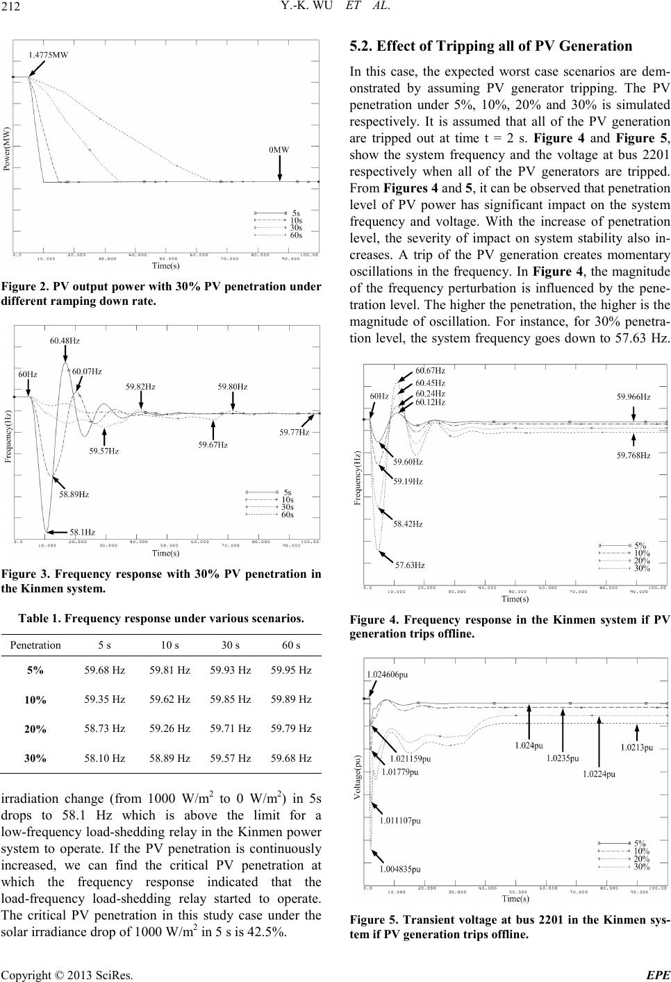 Y.-K. WU ET AL. Copyright © 2013 SciRes. EPE 212 Figure 2 . PV out put pow er with 3 0 % PV pe netr atio n under diff erent ramping down rate. Figure 3. Frequency response with 30% PV penetration in the Kinmen syst em. Table 1. Frequency response under various scenarios. Penetration 5 s 10 s 30 s 60 s 5% 59.68 Hz 59.81 Hz 59.93 Hz 59.95 Hz 10% 59. 35 Hz 59.62 Hz 59.85 Hz 59.89 Hz 20% 58. 73 Hz 59.26 Hz 59.71 Hz 59.79 Hz 30% 58. 10 Hz 58.89 Hz 59.57 Hz 59.68 Hz irradiation change (from 1000 W/m2 to 0 W/m2) in 5s drops to 58.1 Hz which is above the limit for a low-frequency load-shedding rela y in the Kinmen power system to operate. If the PV penetration is continuously increased, we can find the critical PV penetration at which the frequency response indicated that the load-frequency load-shedding relay started to operate. The critical PV penetration in this study case under the solar irradiance drop of 1000 W/m2 in 5 s is 42.5%. 5.2. Effect of Tripping all of PV Generation In this case, the expected worst case scenarios are dem- onstrated by assuming PV generator tripping. The PV penetration under 5%, 10%, 20% and 30% is simulated respectively. It is assumed that all of the PV generation are tripped out at time t = 2 s. Fig ure 4 and Figure 5, show the system frequency and the voltage at bus 2201 respectively when all of the PV generators are tripped. Fro m Figures 4 and 5, it can be observed that penetration level of PV power has significant impact on the system frequency and voltage. With the increase of penetration level, the severity of impact on system stability also in- creases. A trip of the PV generation creates momentary oscillations in the frequency. In Figure 4, the magnitude of the frequency perturbation is influenced by the pene- trat ion leve l. The higher the pene tratio n, the higher is the magnitude of oscillation. For instance, for 30% penetra- tion level, the system frequency goes down to 57.63 Hz. Figure 4. Frequency response in the Kinmen system if PV generati on trips of fline. Figure 5. Transient voltage at bus 2201 in the Kinmen sys- tem if PV generation trips offlin e. 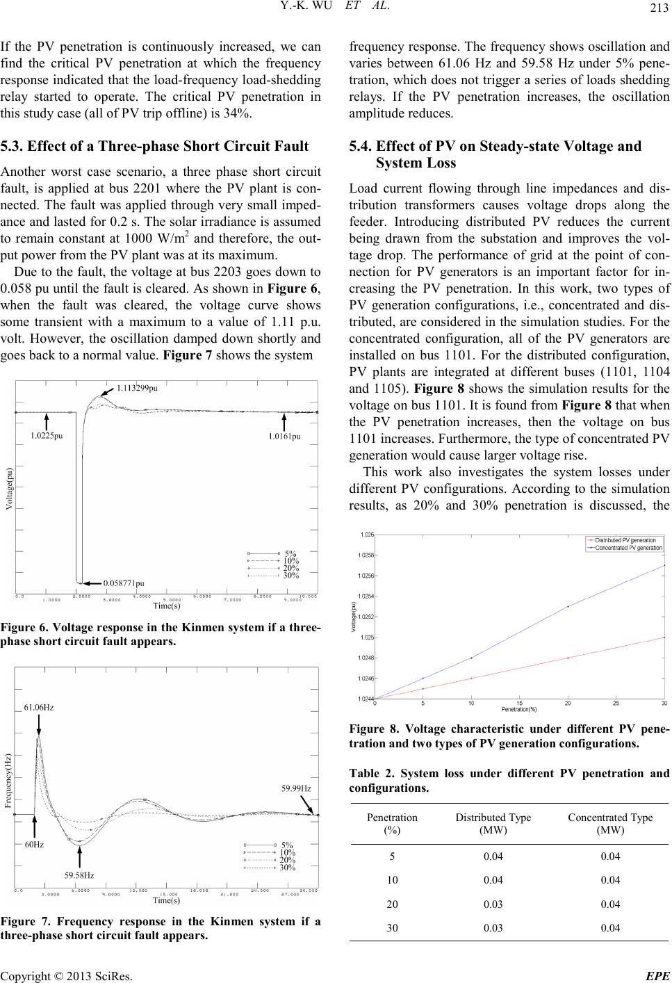 Y.-K. WU ET AL. Copyright © 2013 SciRes. EPE 213 If the PV penetration is continuously increased, we can find the critical PV penetration at which the frequency response indicated that the load-frequency load-shedding relay started to operate. The critical PV penetration in this study case (all of PV trip o ffline) is 34%. 5.3. Effect of a Three-phase Short Circuit Fault Another worst case scenario, a three phase short circuit fault, is applied at bus 2201 where the PV plant is con- nected. The fault was applied through ver y small imped- ance and lasted for 0.2 s. The solar irradiance is assumed to remain constant at 1000 W/m2 and therefore, the out- put po wer fro m the P V plant was at its max imum. Due to the fault, the voltage at bus 2203 goes down to 0.058 pu until the fa ult is cle ar ed . As sho wn in Fig ure 6, when the fault was cleared, the voltage curve shows some transient with a maximum to a value of 1.11 p.u. volt. However, the oscillation damped down shortly and goes back to a normal value. Figure 7 shows the system Figure 6. Voltage respo nse i n the K inmen s yste m if a three- phase short circuit fa ult appe a rs. Figure 7. Frequency response in the Kinmen system if a three-pha se shor t ci rcuit fault appears. frequency response. The frequency shows oscillatio n and varies between 61.06 Hz and 59.58 Hz under 5% pene- tration, which does not trigger a series of loads shedding relays. If the PV penetration increases, the oscillation amplitude reduces. 5.4. Effect of PV on Steady-state Voltage and System Loss Load current flowing through line impedances and dis- tribution transformers causes voltage drops along the feeder. Introducing distributed PV reduces the current being drawn from the substation and improves the vol- tage drop. The performance of grid at the point of con- nection for PV generators is an important factor for in- creasing the PV penetration. In this work, two types of PV generation configurations, i.e., concentrated and dis- tributed, ar e considered in the simulatio n stud ies. Fo r the concentrated configuration, all of the PV generators are installed on bus 1101. For the distributed configuration, PV plants are integrated at different buses (1101, 1104 and 1105). Figure 8 shows the simulation results for the voltage on bus 1101. It is found from Figure 8 that whe n the PV penetration increases, then the voltage on bus 1101 increases. Furthermore, the type of concentrated PV generation would cause larger voltage rise. This work also investigates the system losses under different PV configurations. According to the simulation results, as 20% and 30% penetration is discussed, the Figure 8. Voltage characteristic under different PV pene- tration and two ty pes of PV generat ion configu r ations. Table 2. S y st em loss under different PV penetration and configura tions. Penetration (%) Distributed Type (MW) Concentrated Type (MW) 5 0.04 0.04 10 0.04 0.04 20 0.03 0.04 30 0.03 0.04 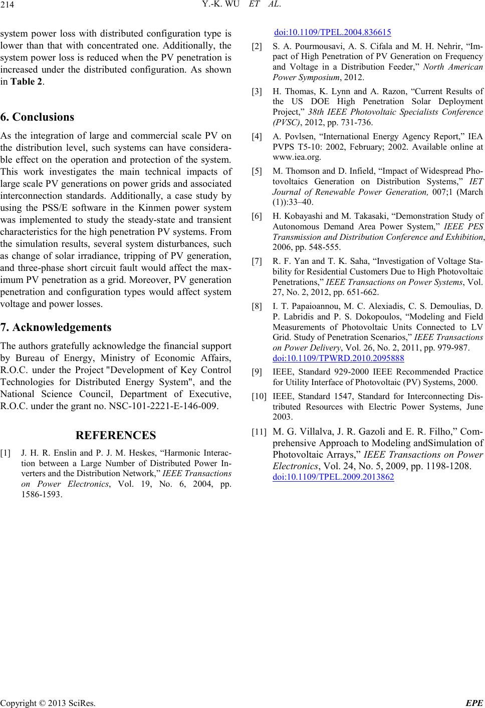 Y.-K. WU ET AL. Copyright © 2013 SciRes. EPE 214 system power loss with distributed configuration type is lower than that with concentrated one. Additionally, the system power loss is reduced when the PV penetration is increased under the distributed configuration. As shown in Table 2. 6. Conclusions As the integration of large and commercial scale PV on the distribution level, such systems can have considera- ble effect on the operation and protection of the system. This work investigates the main technical impacts of large scale PV generations on power grids and associated interconnection standards. Additionally, a case study by using the PSS/E software in the Kinmen power system was implemented to study the steady-state and transient characteristic s for t he hig h pe netratio n PV s ystems . Fro m the simulation results, several system disturbances, such as change of solar irradiance, tripping of PV generation, and three-phase short circuit fault would affect the max- imum PV penetratio n as a grid . Mor eo ver, PV generation penetration and configuration types would affect system voltage and power losses. 7. Acknowledgements The authors grate fully ac kno wledge the fi nancia l support by Bureau of Energy, Ministry of Economic Affairs, R.O.C. under the Project "Development of Key Control Technologies for Distributed Energy System", and the National Science Council, Department of Executive, R.O.C. under the grant no. NSC-101-2221-E-146-009. REFERENCES [1] J. H. R. Enslin and P. J. M. Heskes, “Harmonic In terac- tion between a Large Number of Distributed Power In- verters and the Distribution Netwo rk,” IEEE Transactions on Power Electronics, Vol. 19, No. 6, 2004, pp. 1586-1593. doi:10.1109/TPEL.2004.836615 [2] S. A. Pourmousavi, A. S. Cifala and M. H. Nehrir, “Im- pact of High Penetration of PV Generation on Frequency and Voltage in a Distribution Feeder,” North American Power Symposium, 2012. [3] H. Thomas, K. Lynn and A. Razon, “Current Results of the US DOE High Penetration Solar Deployment Project, ” 38th IEEE Photovoltaic Specialists Conference (PVSC), 2012, pp. 731-736. [4] A. Povlsen, “International Energy Agency Report,” IEA PVPS T5-10: 2002, February; 2002. Available online at www.iea.org. [5] M. Thomson and D. Infield, “Impact o f Widespread Pho- tovoltaics Generation on Distribution Systems,” IET Journal of Renewable Power Generation, 007;1 (March (1)):33–40. [6] H. Kobayashi and M. Takasa ki, “Demonstration Study of Autonomous Demand Area Power System,” IEEE PES Transmission and Distribution Conference and Exhibition, 2006, pp . 548-555. [7] R. F. Yan and T. K. Saha, “Investigation of Voltage Sta- bility for Residential Customers Due to High Photovoltaic Penetrations ,” IEEE Transactions on Power Systems, Vol. 27, No. 2, 2012, pp. 651-662. [8] I. T. Papaioannou, M. C. Alexiadis, C. S. Demoulias, D. P. Labridis and P. S. Dokopoulos, “Modeling and Field Measurements of Photovoltaic Units Connected to LV Grid. Study of Penetration Scenarios,” IEEE Transactions on Pow er D elivery, Vol. 26, No. 2, 201 1, pp. 979-987. doi:10.1109/TPWRD.2010.2095888 [9] IEEE, Standard 929-2000 IEEE Recommended Practice for Utility Interface of Pho tovoltaic (PV) Systems, 2000. [10] IEEE, Standard 1547, Standard for Interconnecting Dis- tributed Resources with Electric Power Systems, June 2003. [11] M. G. Villalva, J . R. Gazoli and E. R. Fil ho,” Co m- prehensive Approach to Modeling andSimulation of Photovoltaic Arrays,” IEEE Transactions on Power Electronics, Vol. 24, No. 5, 2009, pp. 1198-1208. doi:10.1109/TPEL.2009.2013862 |