

Paper Menu >>
Journal Menu >>
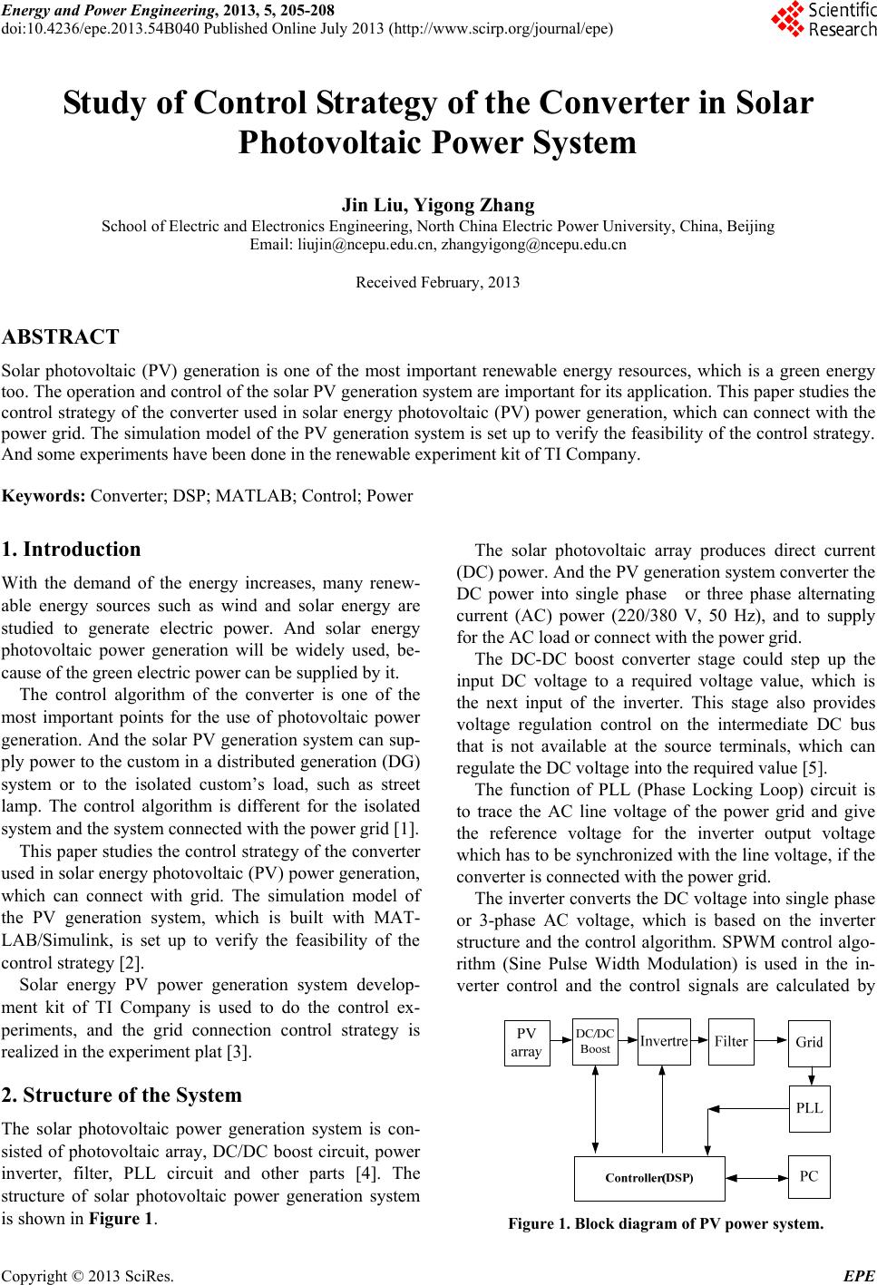 Energy and Power Engineering, 2013, 5, 205-208 doi:10.4236/epe.2013.54B040 Published Online July 2013 (http://www.scirp.org/journal/epe) Study of Control Strategy of the Converter in Solar Photovoltaic Power System Jin Liu, Yigong Zhang School of Electric and Electronics Engineering, North China Electric Power University, China, Beijing Email: [email protected], [email protected] Received February, 2013 ABSTRACT Solar photovoltaic (PV) generation is one of the most important renewable energy resources, which is a green energy too. The operation and control of the solar PV generation system are important for its application. This paper studies the control strategy of the converter used in solar energy photovoltaic (PV) power generation, which can connect with the power grid. The simulation model of the PV generation syste m is set up to verify the feasibility of the con trol strategy. And some experiments have been done in the renewable experiment kit of TI Company. Keywords: Converter; DSP; MATLAB; Control; Power 1. Introduction With the demand of the energy increases, many renew- able energy sources such as wind and solar energy are studied to generate electric power. And solar energy photovoltaic power generation will be widely used, be- cause of the green electric power can be supplied by it. The control algorithm of the converter is one of the most important points for the use of photovoltaic power generation. And the solar PV generation system can sup- ply power to the custom in a distributed generation (DG) system or to the isolated custom’s load, such as street lamp. The control algorithm is different for the isolated system and the system connected with the power grid [1]. This paper studies the control strategy of the converter used in solar energy photovoltaic (PV) power generation, which can connect with grid. The simulation model of the PV generation system, which is built with MAT- LAB/Simulink, is set up to verify the feasibility of the control strategy [2]. Solar energy PV power generation system develop- ment kit of TI Company is used to do the control ex- periments, and the grid connection control strategy is realized in the experiment plat [3]. 2. Structure of the System The solar photovoltaic power generation system is con- sisted of photovoltaic array, DC/DC boost circuit, power inverter, filter, PLL circuit and other parts [4]. The structure of solar photovoltaic power generation system is shown in Figure 1. The solar photovoltaic array produces direct current (DC) power. An d the PV g e neratio n system conv er ter th e DC power into single phase or three phase alternating current (AC) power (220/380 V, 50 Hz), and to supply for the AC load or connect with the power grid. The DC-DC boost converter stage could step up the input DC voltage to a required voltage value, which is the next input of the inverter. This stage also provides voltage regulation control on the intermediate DC bus that is not available at the source terminals, which can regulate the DC voltage into the required value [5]. The function of PLL (Phase Locking Loop) circuit is to trace the AC line voltage of the power grid and give the reference voltage for the inverter output voltage which has to be synchronized with the line voltage, if the converter is connected with the power grid. The inverter converts the DC voltage into single ph ase or 3-phase AC voltage, which is based on the inverter structure and the control algorithm. SPWM control algo- rithm (Sine Pulse Width Modulation) is used in the in- verter control and the control signals are calculated by Figure 1. Block diagram of PV power system. Copyright © 2013 SciRes. EPE 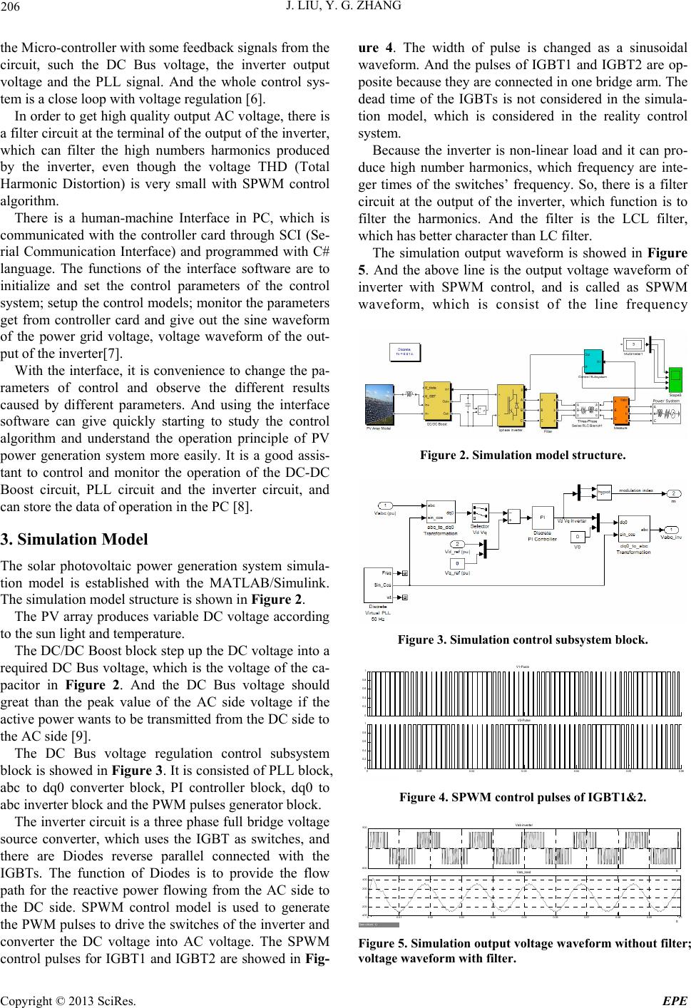 J. LIU, Y. G. ZHANG 206 the Micro-controller with some feedback signals from the circuit, such the DC Bus voltage, the inverter output voltage and the PLL signal. And the whole control sys- tem is a close loop with voltage regulation [6]. In order to get high quality output AC voltage, there is a filter circuit at the terminal of the output of the inverter, which can filter the high numbers harmonics produced by the inverter, even though the voltage THD (Total Harmonic Distortion) is very small with SPWM control algorithm. There is a human-machine Interface in PC, which is communicated with the controller card through SCI (Se- rial Communication Interface) and programmed with C# language. The functions of the interface software are to initialize and set the control parameters of the control system; setup the control models; monitor the p arameters get from controller card and give out the sine waveform of the power grid voltage, voltage waveform of the out- put of the inverter[7]. With the interface, it is convenience to change the pa- rameters of control and observe the different results caused by different parameters. And using the interface software can give quickly starting to study the control algorithm and understand the operation principle of PV power generation system more easily. It is a good assis- tant to control and monitor the operation of the DC-DC Boost circuit, PLL circuit and the inverter circuit, and can store the data of operation in the PC [8]. 3. Simulation Model The solar photovoltaic power generation system simula- tion model is established with the MATLAB/Simulink. The simulation model structure is shown in Figur e 2. The PV array produces variable DC voltage according to the sun light and temperature. The DC/DC Boost block step up the DC voltage into a required DC Bus voltage, which is the voltage of the ca- pacitor in Figure 2. And the DC Bus voltage should great than the peak value of the AC side voltage if the active power wants to be transmitted from the DC side to the AC side [9]. The DC Bus voltage regulation control subsystem block is showed in Figure 3. It is consisted of PLL block, abc to dq0 converter block, PI controller block, dq0 to abc inverter block and the PWM pulses generator block. The inverter circuit is a three phase full bridge voltage source converter, which uses the IGBT as switches, and there are Diodes reverse parallel connected with the IGBTs. The function of Diodes is to provide the flow path for the reactive power flowing from the AC side to the DC side. SPWM control model is used to generate the PWM pulses to drive the switches of the inverter and converter the DC voltage into AC voltage. The SPWM control pulses for IGBT1 and IGBT2 are showed in Fig- ure 4. The width of pulse is changed as a sinusoidal waveform. And the pulses of IGBT1 and IGBT2 are op- posite because they are connected in one bridge arm. The dead time of the IGBTs is not considered in the simula- tion model, which is considered in the reality control system. Because the inverter is non-linear load and it can pro- duce high number harmonics, which frequency are inte- ger times of the switches’ frequency. So, there is a filter circuit at the output of the inverter, which function is to filter the harmonics. And the filter is the LCL filter, which has better character than LC filter. The simulation output waveform is showed in Figure 5. And the above line is the output voltage waveform of inverter with SPWM control, and is called as SPWM waveform, which is consist of the line frequency Figure 2. Simulation model structure. Figure 3. Simulation control subsyste m bloc k. 0 0.2 0.4 0.6 0.8 1 V1-Pusle 00.01 0.02 0.03 0.04 0.05 0.06 0 0.2 0.4 0.6 0.8 1 V2-Pulse Figure 4. SPWM control pulses of IGBT1&2. -500 0 500 S Vab inverter 00.01 0.02 0.03 0.04 0.050.06 0.07 0.08 0.090.1 -400 -200 0 200 400 S Vab_load Figure 5. Simulation output voltage waveform without filter; voltage waveform with fi lter. Copyright © 2013 SciRes. EPE 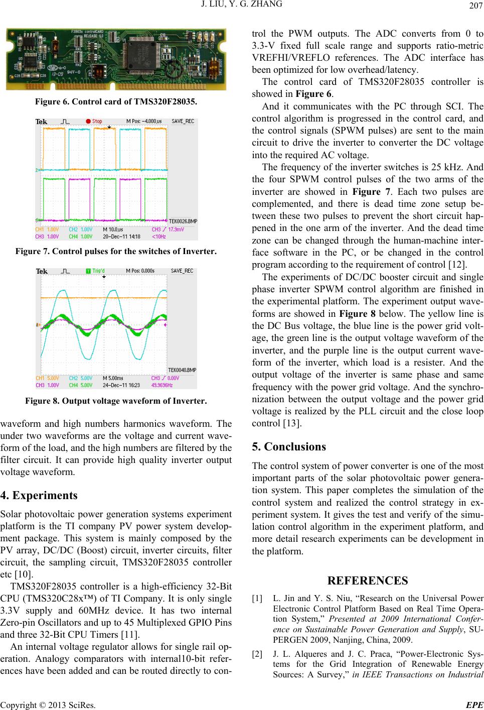 J. LIU, Y. G. ZHANG 207 Figure 6. Control card of TMS320F28035. Figure 7. Control pulses for the switches of Inverter. Figure 8. Output voltage waveform of Inverter. waveform and high numbers harmonics waveform. The under two waveforms are the voltage and current wave- form of the load, and the high numbers are filtered by the filter circuit. It can provide high quality inverter output voltage waveform. 4. Experiments Solar photovoltaic power generation systems experiment platform is the TI company PV power system develop- ment package. This system is mainly composed by the PV array, DC/DC (Boost) circuit, inverter circuits, filter circuit, the sampling circuit, TMS320F28035 controller etc [10]. TMS320F28035 controller is a high-efficiency 32-Bit CPU (TMS320C28x™) of TI Company. It is only single 3.3V supply and 60MHz device. It has two internal Zero-pin Oscillators and up to 45 Multip lexed GPIO Pins and three 32-Bit CPU Timers [11]. An internal voltage regulator allows for single rail op- eration. Analogy comparators with internal10-bit refer- ences have been added and can be routed directly to con- trol the PWM outputs. The ADC converts from 0 to 3.3-V fixed full scale range and supports ratio-metric VREFHI/VREFLO references. The ADC interface has been optimized for low overhead/latency. The control card of TMS320F28035 controller is showed in Figure 6. And it communicates with the PC through SCI. The control algorithm is progressed in the control card, and the control signals (SPWM pulses) are sent to the main circuit to drive the inverter to converter the DC voltage into the required AC voltage. The frequency of the inverter switches is 25 kHz. And the four SPWM control pulses of the two arms of the inverter are showed in Figure 7. Each two pulses are complemented, and there is dead time zone setup be- tween these two pulses to prevent the short circuit hap- pened in the one arm of the inverter. And the dead time zone can be changed through the human-machine inter- face software in the PC, or be changed in the control program according to the requirement of control [12]. The experiments of DC/DC booster circuit and single phase inverter SPWM control algorithm are finished in the experimental platform. The experiment output wave- forms are showed in Figure 8 below. The yellow line is the DC Bus voltage, the blue line is the power grid volt- age, the green line is the output voltage waveform of the inverter, and the purple line is the output current wave- form of the inverter, which load is a resister. And the output voltage of the inverter is same phase and same frequency with the power grid voltage. And the synchro- nization between the output voltage and the power grid voltage is realized by the PLL circuit and the close loop control [13 ] . 5. Conclusions The control syste m of power converter is one of th e most important parts of the solar photovoltaic power genera- tion system. This paper completes the simulation of the control system and realized the control strategy in ex- periment system. It gives the test and verify of the simu- lation control algorithm in the experiment platform, and more detail research experiments can be development in the platform. REFERENCES [1] L. Jin and Y. S. Niu, “Research on the Universal Power Electronic Control Platform Based on Real Time Opera- tion System,” Presented at 2009 International Confer- ence on Sustainable Power Generation and Supply, SU- PERGEN 2009, Nanjing, China, 2009. [2] J. L. Alqueres and J. C. Praca, “Power-Electronic Sys- tems for the Grid Integration of Renewable Energy Sources: A Survey,” in IEEE Transactions on Industrial Copyright © 2013 SciRes. EPE  J. LIU, Y. G. ZHANG Copyright © 2013 SciRes. EPE 208 Electronics, Vol. 53, No. 4, 2006. [3] S. B. Kjear, K. P. John and F. Blaabjerg, “A Review of Single-Phase Grid-Connected Inverters for Photovoltaic Modules,” IEEE Transactions on Industry Applications, Vol. 41, No. 5, 2005. [4] X. Y. Wang and M. Kazerani, “A Multicarrier Modular Photovoltaic Grid-connected Inverter with a New Phase-shift Rule,” Electric Power Systems Research, Vol. 77, No. 7, 2007, pp. 754-760. doi:10.1016/j.epsr.2006.06.010 [5] J. C. Jia, J. Liu and Y. G. Zhang, “Novel Reactive Power Optimization Control Strategy for Doubly Fed Induction Wind Power Generation System,” Proceedings of the Chinese Society of Electrical Engineering, Vol. 30, No. 30, 2010, pp. 87-92. [6] Al-Amoudi and A. L. Zhang, “Optional Control of a Grid- Connected PV System for Maximum Power Point Tracking and Unity Power Factor,” Power Electronics and Variable Speed Drives, 1998, pp. 21-23. [7] S. B. Kjear, K. P. John and F. Blaabjerg, “A Review of Single-Phase Grid-Connected Inverters for Photovoltaic Modules,” IEEE Transactions on Industry Applications, Vol. 41, No. 5, 2005. [8] Timothy, C. Y. Wang, Z. H. Ye, G. Sinha, et al., “Output Filter Design for a Grid-interconnected Three-phase In- verter,” Power Electronics Specialist Conference, IEEE 34th Annual, No. 2, 2003, pp. 779-784. [9] X. Y. Wang and M. Kazerani, “A Multicarrier Modular Photovoltaic Grid-connected Inverter with a New Phase-shift Rule,” Electric Power Systems Research, Vol. 77, No. 7, 2007, pp. 754-760. doi:10.1016/j.epsr.2006.06.010 [10] Implementing a Digitally Controlled Renewable Energy. [11] DSP TMS320F28035, Datasheet: http://www.ti.com. [12] F28xxx User’s Guides. http://www.ti.com/f28xuserguide [13] TMS320, “Fixed-Point DSP Assembly Language Tools User’s Guide,” Texas Instruments,1991, pp. 78-123. |