

Paper Menu >>
Journal Menu >>
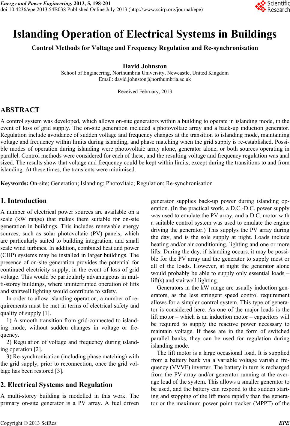 Energy and Power Engineering, 2013, 5, 198-201 doi:10.4236/epe.2013.54B038 Published Online July 2013 (http://www.scirp.org/journal/epe) Islanding Operation of Electrical Systems in Buildings Control Methods for Voltage and Frequency Regulation and Re-synchronisation David Johnston School of Engineering, Northumbria University, Newcastle, United Kingdom Email: [email protected] Received February, 2013 ABSTRACT A control system was developed, which allows on-site generators within a building to operate in islanding mode, in the event of loss of grid supply. The on-site generation included a photovoltaic array and a back-up induction generator. Regulation include avoidance of sudden voltage and frequency changes at the transition to islanding mode, maintaining voltage and frequency within limits during islanding, and phase matching when the grid supply is re-established. Possi- ble modes of operation during islanding were photovoltaic array alone, generator alone, or both sources operating in parallel. Control methods were considered for each of these, and the resulting voltage and frequency regulation was anal sized. The results show that voltage and frequency could be kept within limits, except during the transitions to and from islanding. At these times, the transients were minimised. Keywords: On-site; Generation; Islanding; Photovltaic; Regulation; Re-synchronisation 1. Introduction A number of electrical power sources are available on a scale (kW range) that makes them suitable for on-site generation in buildings. This includes renewable energy sources, such as solar photovoltaic (PV) panels, which are particularly suited to building integration, and small scale wind turbines. In addition, combined heat and power (CHP) systems may be installed in larger buildings. The presence of on-site generation provides the potential for continued electricity supply, in the event of loss of grid voltage. This would be particularly advantageous in mul- ti-storey buildings, where uninterrupted operation of lifts and stairwell lighting would contribute to safety. In order to allow islanding operation, a number of re- quirements must be met in terms of electrical safety and quality of supply [1]. 1) A smooth transition from grid-connected to island- ing mode, without sudden changes in voltage or fre- quency. 2) Regulation of voltage and frequency during island- ing operation [2]. 3) Re-synchronisation (including phase matching) with the grid supply, prior to reconnection, once the grid vol- tage has been restored [3]. 2. Electrical Systems and Regulation A multi-storey building is modelled in this work. The primary on-site generator is a PV array. A fuel driven generator supplies back-up power during islanding op- eration. (In the practical work, a D.C.-D.C. power supply was used to emulate the PV array, and a D.C. motor with a suitable control system was used to emulate the engine driving the generator.) This supplys the PV array during the day, and is the sole supply at night. Loads include heating and/or air conditioning, lighting and one or more lifts. During the day, if islanding occurs, it may be possi- ble for the PV array and the generator to supply most or all of the loads. However, at night the generator alone would probably be able to supply only essential loads – lift(s) and stairwell lighting. Generators in the kW range are usually induction gen- erators, as the less stringent speed control requirement allows for a simpler control system. This type of genera- tor is considered here. As one of the major loads is the lift motor – which is an induction motor – capacitors will be required to supply the reactive power necessary to maintain voltage. If these are in the form of switched parallel banks, they can be used for regulation during islanding mode. The lift motor is a large occasional load. It is supplied from a battery bank via a variable voltage variable fre- quency (VVVF) inverter. The battery in turn is recharged from the PV array and/or generator running at the aver- age load of the system. This allows a smaller generator to be used, and the battery can respond to the sudden start- ing and stopping of the lift more rapidly than the genera- tor or the maximum power point tracker (MPPT) of the Copyright © 2013 SciRes. EPE 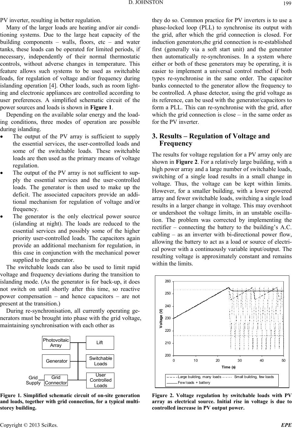 D. JOHNSTON 199 PV inverter, resulting in better regulation. Many of the larger loads are heating and/or air condi- tioning systems. Due to the large heat capacity of the building components – walls, floors, etc – and water tanks, these loads can be operated for limited periods, if necessary, independently of their normal thermostatic controls, without adverse changes in temperature. This feature allows such systems to be used as switchable loads, for regulation of voltage and/or frequency during islanding operation [4]. Other loads, such as room light- ing and electronic appliances are controlled according to user preferences. A simplified schematic circuit of the power sources and loads is shown in Figure 1. Depending on the available solar energy and the load- ing conditions, three modes of operation are possible during islanding. The output of the PV array is sufficient to supply the essential services, the user-controlled loads and some of the switchable loads. These switchable loads are then used as the primary means of voltage regulation. The output of the PV array is not sufficient to sup- ply the essential services and the user-controlled loads. The generator is then used to make up the deficit. The associated capacitors provide an addi- tional mechanism for regulation of voltage and/or frequency. The generator is the only electrical power source (islanding at night). The loads are reduced to the essential services and possibly some of the higher priority user-controlled loads. The capacitors again provide an additional mechanism for regulation, in this case in conjunction with the mechanical power supplied to the generator. The switchable loads can also be used to limit rapid voltage and frequency deviations during the transition to islanding mode. (As the generator is for back-up, it does not switch on until shortly after this time, so reactive power compensation – and hence capacitors – are not present at the transition.) During re-synchronisation, all currently operating ge- nerators must be brought into phase with the grid voltage, maintaining synchronisation with each other as Photovoltaic Array Generator Lift Swit cha ble Loads User Controlled Loads Grid Connector Grid Suppl y Figure 1. Simplified schematic circuit of on-site generation and loads, together with grid connection, for a typical multi- storey building. they do so. Common practice for PV inverters is to use a phase-locked loop (PLL) to synchronise its output with the grid, after which the grid connection is closed. For induction generators,the grid connection is re-established first (generally via a soft start unit) and the generator then automatically re-synchronises. In a system where either or both of these generators may be operating, it is easier to implement a universal control method if both types re-synchronise in the same order. The capacitor banks connected to the generator allow the frequency to be controlled. A phase detector, using the grid voltage as its reference, can be used with the generator/capacitors to form a PLL. This can re-synchronise with the grid, after which the grid connection is close – in the same order as for the PV inverter. 3. Results – Regulation of Voltage and Frequency The results for voltage regulation for a PV array only are shown in Figure 2. For a relatively large building, with a high power array and a large number of switchable loads, switching of a single load results in a small change in voltage. Thus, the voltage can be kept within limits. However, for a smaller building, with a lower powered array and fewer switchable loads, switching a single load results in a larger change in voltage. This may overshoot or undershoot the voltage limits, in an unstable oscilla- tion. The problem was corrected by implementing the rectifier – connecting the battery to the building’s A.C. cabling – as an inverter with bi-directional power flow, allowing the battery to act as a load or source of electri- cal power with a continuously variable input/output. The resulting voltage is approximately constant and remains within the limits. 200 210 220 230 240 250 260 0 102030405 Time (s) Voltage (V) 0 Large bui ldi ng, many loadsSmall building, few loads F ew loads + battery Figure 2. Voltage regulation by switchable loads with PV array as electrical source. Initial rise in voltage is due to controlled increase in PV output power. Copyright © 2013 SciRes. EPE  D. JOHNSTON 200 The capacitor banks (one on each phase) and the pow- er applied to the generator were used to control the volt- ages and frequency, in a two-input – two-output control system, for maximum flexibility. Each capacitor bank had capacitors of 1 μF, 2 μF, 4 μF, 8 μF and 16 μF, al- lowing the total capacitance to be varied in 1 μF steps up to a maximum of 31 μF. This allowed fine control of both voltage and frequency, and was thus able to keep both of these close to their nominal values. It was observed that switching of the capacitors al- lowed a more rapid response than changes in the genera- tor power alone, resulting in better regulation. In addition, the capacitor banks on each phase allowed individual control of each phase voltage to compensate for unbal- anced loading. Large and rapid changes in voltage and frequency oc- curred during the transition to islanding operation, de- pending on the loading at the time relative to the level of on-site generation. Where the load was larger than the generation, as shown in Figure 3, there was a drop in voltage, and to a lesser extent in frequency. By drawing power from the battery, via the inverter, the deficit could be largely compensated for, thus reducing both the depth and duration of the voltage and frequency deviations. This is also shown in Figure 3. As the graph shows, the voltage deviation and frequency deviation both exceed the limits (E.U. limits -6/+10 %) for approx. one second. Figure 4 shows the effects of re-synchronising the generator prior to reconnection to the grid. In Figure 4(a), re-synchronisation is not applied, and there is in general a phase mismatch at the moment of reconnection. This results in a large transient in both voltage and cur- rent, until the torque on the generator brings it into phase with the grid voltage. As can be seen in the graph, the peak of the transient voltage can be over 1000 V, leading to damage of the generator, cabling and other equipment. Figure 4(b) shows the results when the capacitor banks are used to control the phase and achieve re-synchroni- sation. The transient is much lower – typically 50% lar- ger than the nominal voltage. The will generally not be sufficient to damage the generator or cabling, although sensitive equipment, such as electronic appliances might be affected. When both the PV array and generator were operating during re-synchronisation and reconnection, it was found that they maintained better phase matching with each other if the PV inverter tracked the phase of the generator, rather than vice versa. The moment of inertia of the gen- erator resulted in a slower time response than for the PV inverter, making it difficult to maintain phase matching. Conversely, the rapid response of the PV inverter al- lowed it to easily track changes in the phase of the gen- erator output. 150 170 190 210 230 250 012345678910 Time (s) Voltage (V) W ithout battery p owerWith batte ry powe r (a) 47.5 48 48.5 49 49.5 50 50.5 012345678910 Tim e (s) Freque ncy (Hz) W ithou t battery powerWith battery power (b) Figure 3. (a) Voltage deviation during transition to island- ing operation showing effect of battery power; (b) Fre- quency deviation. 4. Conclusions and Further Work By using the control systems and methods described, the voltage and frequency could be kept within limits throughout most of the duration of the islanding period. However, transients remained at the start of islanding and at reconnection to the grid, although the measures adopted reduced the magnitude of these transients. Further work may reduce them to the point where they no longer ex- ceed operating limits. The control methods described provided regulation in each of the operating modes – PV array only, generator only, and both systems operating. For a control system to be fully universal, it would need to be able to detect which power sources are operating, and adopt the appro- priate control method. This could be implemented via a micro-controller for maximum flexibility and will be one of the main topics for future work. Copyright © 2013 SciRes. EPE  D. JOHNSTON Copyright © 2013 SciRes. EPE 201 ( -1500 -1000 -500 0 500 1000 1500 -1 -0.500.51 Time (s) Voltage (V) a) bution network control system [7]. Future work could include integrating these islanding operation methods with smart grid technology. 5. Acknowledgements The author would like to thank Prof. Ghanim Putrus, Dr. Edward Bentley, Dr. Mahinsasa Narayana and Dr. Jaya- raman Ramachandra for their collaboration on previous projects on islanding operation of PV systems and induc- tion generators, which have contributed to this work. REFERENCES [1] R. Caldon, A. Stocco and R. Turri, “Feasibility of Adap- tive Intentional Islanding Operation of Electric Utility Systems with Distributed Generation,” Electric Power Systems Research, Vol. 78, No. 12, December 2008, pp 2017-2023. doi:10.1016/j.epsr.2008.06.007 -400 -300 -200 -100 0 100 200 300 400 500 -1-0.5 0 0.51 Time (s) Voltage (V) [2] A. Llaria, O. Curea, J. Jiménez and H. Camblong, “Sur- vey on microgrids: Unplanned Islanding and Related In- verter Control Techniques,” Renewable Energy, Vol. 36, No. 8, August 2011, pp. 2052-2061. doi:10.1016/j.renene.2011.01.010 [3] J. J. Joglekar and Y. P. Nerkar, “A Different Approach in System Restoration with Special Consideration of Island- ing Schemes,” International Journal of Electrical Power & Energy Systems, Vol. 30, No. 9, November 2008, pp. 519-524. doi:10.1016/j.ijepes.2008.04.003 [4] P. A. Trodden, W. A. Bukhsh, A. Grothey and K. I. M. McKinnon, “MILP Formulation for Controlled Islanding of Power Networks,” International Journal of Electrical Power & Energy Systems, Vol. 45, No. 1, February 2013, pp. 501-508. doi:10.1016/j.ijepes.2012.09.018 (b) [5] B. Yu, M. Matsui and G. Yu, “A Review of Current Anti-islanding Methods for Photovoltaic Power System,” Solar Energy, Vol. 84, No. 5, May 2010, pp. 745-754. doi:10.1016/j.solener.2010.01.018 Figure 4. Voltage transient at re-connection. (a) Without re-synchronisation. (b) With re-synchronisation. [6] D. Velasco, C. L. Trujillo, G. Garcerá and E. Figueres, “Review of Anti-islanding Techniques in Distributed Generators,” Renewable and Sustainable Energy Reviews, Vol. 14, No. 6, August 2010, pp. 1608-1614. doi:10.1016/j.rser.2010.02.011 In the work described, islanding was initiated by a controlled disconnection at the grid input. In a real situa- tion, islanding would be due to a fault elsewhere on the distribution network, resulting in a loss of grid voltage. The building’s electrical control system would need to detect this condition, and switch to islanding operation [5, 6]. This could be achieve by monitoring the grid condi- tion – voltage, frequency, impedance, etc – or by an ac- tive signal, indicating occurrence of the fault. In the latter case, this would involve communication between the building’s electrical control system and the local distri- [7] A. Moeini, A. Darabi, S. M. R. Rafiei and M. Karimi, “Intelligent Islanding Detection of a Syn- chronous Distributed Generation Using Governor Signal Clustering,” Electric Power Systems Re- search, Vol. 81, No. 2, February 2011, pp. 608-616. doi:10.1016/j.epsr.2010.10.023 |