

Paper Menu >>
Journal Menu >>
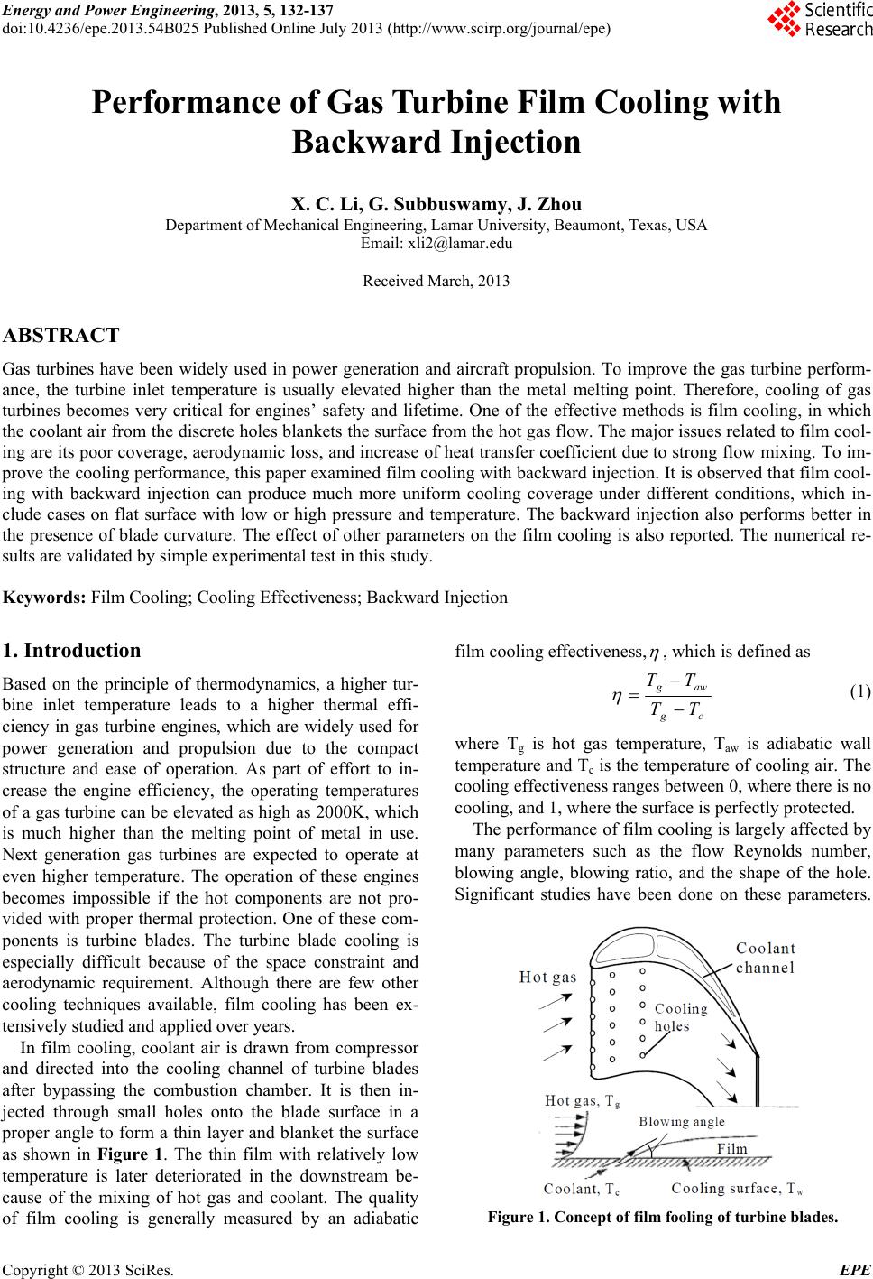 Energy and Power Engineering, 2013, 5, 132-137 doi:10.4236/epe.2013.54B025 Published Online July 2013 (http://www.scirp.org/journal/epe) Performance of Gas Turbine Film Cooling with Backward Injection X. C. Li, G. Subbuswamy, J. Zhou Department of Mechanical Engineering, Lamar University, Beaumont, Texas, USA Email: [email protected] Received March, 2013 ABSTRACT Gas turbines have been widely used in power generation and aircraft propulsion. To improve the gas turbine perform- ance, the turbine inlet temperature is usually elevated higher than the metal melting point. Therefore, cooling of gas turbines becomes very critical for engines’ safety and lifetime. One of the effective methods is film cooling, in which the coolant air from the discrete holes blankets the surface from the hot gas flow. The major issues related to film cool- ing are its poor coverage, aerodynamic loss, and increase of heat transfer coefficient due to strong flow mixing. To im- prove the cooling p erformance, this paper examined film cooling with b ackward injection. It is observed that film cool- ing with backward injection can produce much more uniform cooling coverage under different conditions, which in- clude cases on flat surface with low or high pressure and temperature. The backward injection also performs better in the presence of blade curvature. The effect of other parameters on the film cooling is also reported. The numerical re- sults are validated by simple experimental test in th is study. Keywords: Film Cooling; Cooling Effectiven ess; Backward Injection 1. Introduction Based on the principle of thermodynamics, a higher tur- bine inlet temperature leads to a higher thermal effi- ciency in gas turbine engines, which are widely used for power generation and propulsion due to the compact structure and ease of operation. As part of effort to in- crease the engine efficiency, the operating temperatures of a gas turbine can be elevated as high as 2000K, which is much higher than the melting point of metal in use. Next generation gas turbines are expected to operate at even higher temperature. The operation of these engines becomes impossible if the hot components are not pro- vided with proper thermal protection. One of these com- ponents is turbine blades. The turbine blade cooling is especially difficult because of the space constraint and aerodynamic requirement. Although there are few other cooling techniques available, film cooling has been ex- tensively studied and applied over years. In film cooling, coolant air is drawn from compressor and directed into the cooling channel of turbine blades after bypassing the combustion chamber. It is then in- jected through small holes onto the blade surface in a proper angle to form a thin layer and blanket the surface as shown in Figure 1. The thin film with relatively low temperature is later deteriorated in the downstream be- cause of the mixing of hot gas and coolant. The quality of film cooling is generally measured by an adiabatic film cooling effectiveness, , which is defined as cg awg TT TT (1) where Tg is hot gas temperature, Taw is adiabatic wall temperature and Tc is the temperature of coolin g air. The cooling effectiveness ranges between 0, where there is no cooling, and 1, where the surface is perfectly protected. The performance of film cooling is largely affected by many parameters such as the flow Reynolds number, blowing angle, blowing ratio, and the shape of the hole. Significant studies have been done on these parameters. Figure 1. Concept of film fooling of turbine blades. Copyright © 2013 SciRes. EPE 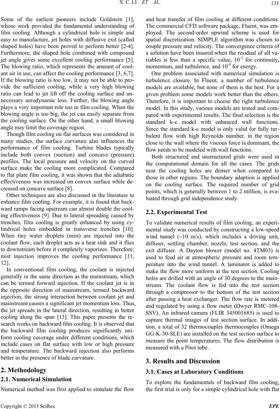 X. C. LI ET AL. 133 Some of the earliest pioneers include Goldstein [1], whose work provided the fundamental understanding of film cooling. Although a cylindrical hole is simple and easy to manufacture, jet holes with diffusive exit (called shaped holes) have been proved to perform better [2-4]. Furthermore, the shaped hole combined with compound jet angle gives some excellent cooling performance [5]. The blowing ratio, which represents the amount of cool- ant air in use, can affect the cooling performance [3, 6,7]. If the blowing ratio is too low, it may not be able to pro- vide the sufficient cooling, while a very high blowing ratio can lead to jet lift off the cooling surface and un- necessary aerodynamic loss. Further, the blowing angle plays a very important role too in film cooling. When the blowing angle is too big, the jet can easily separate from the cooling surface. On the other hand, a small blowing angle may limit the coverage region. Though film cooling on flat surfaces was considered in many studies, the surface curvature also influences the performance of film cooling. Turbine blades typically include both convex (suction) and concave (pressure) profiles. The local pressure and velocity on the curved surface make the cooling more complicated. Compared to flat plate film cooling, it was shown that the adiabatic effectiveness was increased on convex surface while de- creased on concave surface [8]. Other techniques are also discussed in the literature to enhance film cooling. For example, it is found that back- ward ramps facing upstream can almost double the cool- ing effectiveness [9]. Due to lateral spreading caused by trenches, film cooling is greatly enhanced by using cy- lindrical holes embedded in transverse trenches [10]. When tiny water droplets (mist) are injected into the coolant flow, each droplet acts as a heat sink and it flies to downstream before it completely vaporizes. Therefore, mist injection improves the cooling performance [11, 12]. In conventional film cooling, the coolant is injected generally in the same direction as the mainstream, which can be termed forward injection. If the coolant jet is in the opposite direction of mainstream, termed backward injection, the strong interaction between coolant jet and mainstream causes a significant je t momentum loss. Thus, the jet spreads in the lateral direction, resulting in better cooling along the span [13]. This paper presents the re- search works on backward film cooling. It is observed that the backward film cooling produces significantly uni- form cooling coverage under different conditions, which include cases on flat surface with low or high pressure and temperature. The backward injection also performs better in the presence of blade curvature. 2. Methodology 2.1. Numerical Simulation Numerical method was first applied to simulate the flow and heat transfer of film cooling at different conditions. The commercial CFD software package, Fluent, was em- ployed. The second-order upwind scheme is used for spatial discretization. SIMPLE algorithm was chosen to couple pressure and velocity. The convergence criteria of a solution have been insured when the residual of all va- riables is less than a specific value, 10-5 for continuity, momentum, and turbulence, and 10-8 for ene rgy . One problem associated with numerical simulation is turbulence closure. In Fluent, a number of turbulence models are available, but none of them is the best. For a given problem some models work better than the others. Therefore, it is important to choose the right turbulence model. In this study, various models are tested and com- pared with experimental results. The final selection is the standard k- model with enhanced wall functions. Since the standard k- model is only valid for fully tur- bulent flow with high Reynolds number, in the region close to the wall where the viscous force is dominant, the flow needs to be modeled with wall functions. Both structured and unstructured grids were used in the computational domain for all the cases. The grids near the cooling holes are denser when compared to those in other regions. The boundary adaption is applied on the cooling surface. The required number of grid points, which is generally between 1 to 2 million, is eva- luated through grid independence study. 2.2. Experimental Test To validate numerical results of film cooling, an experi- mental study was conducted by constructing a low-speed wind tunnel (~10 m/s), which includes a driving unit, diffuser, settling chamber, nozzle, test section, and the exit diffuser. A Dayton blower (model no. 4TM03) is used to feed air at atmospheric pressure and room tem- perature into the wind tunnel. A laminator is added to make the flow more uniform at the test section. Cooling holes are drilled with an angle of 30 degrees to the main- stream. The coolant flow is fed into the test section through a compressor to the bottom of the test section after passing a heat exchanger. The flow rate is metered and regulated by using a flow meter (Dwyer RMC-108- SSV). An infrared camera (FLIR 345001685) is used to capture thermal images of test section surface. In addi- tion, a total of 32 thermocouples thermocouples (Omega GG-K-30-SLE) are installed on the test section surface to measure the point temperatures. The flow distribution is measured with a Pitot tube. 3. Results and Discussion 3.1. Cases at Laboratory Conditions To explore the fundamentals of backward film cooling, the first trial is only for a simple cylindrical hole with flat Copyright © 2013 SciRes. EPE 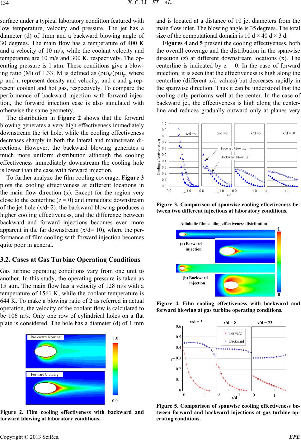 X. C. LI ET AL. 134 surface under a typical laboratory condition featured with low temperature, velocity and pressure. The jet has a diameter (d) of 1mm and a backward blowing angle of 30 degrees. The main flow has a temperature of 400 K and a velocity of 10 m/s, while the coolant velocity and temperature are 10 m/s and 300 K, respectively. The op- erating pressure is 1 atm. These conditions give a blow- ing ratio (M) of 1.33. M is defined as (u)c/(u)g, where and u represent density and velocity, and c and g rep- resent coolant and hot gas, respectively. To compare the performance of backward injection with forward injec- tion, the forward injection case is also simulated with otherwise the same geometry. The distribution in Figure 2 shows that the forward blowing generates a very high effectiveness immediately downstream the jet hole, while the cooling effectiveness decreases sharply in both the lateral and mainstream di- rections. However, the backward blowing generates a much more uniform distribution although the cooling effectiveness immediately downstream the cooling hole is lower than the case with forward injection. To further analyze the film cooling coverage, Figure 3 plots the cooling effectiveness at different locations in the main flow direction (x). Except for the region very close to the centerline (z = 0) and immediate downstream of the jet hole (x/d~2), the backward blowing produces a higher cooling effectiveness, and the difference between backward and forward injections becomes even more apparent in the far downstream (x/d= 10), where the per- formance of film cooling with forward injection becomes quite poor in general. 3.2. Cases at Gas Turbine Operating Conditions Gas turbine operating conditions vary from one unit to another. In this study, the operating pressure is taken as 15 atm. The main flow has a velocity of 128 m/s with a temperature of 1561 K, while the coolant temperature is 644 K. To make a blowing ratio of 2 as referred in actual operation, the velocity of the coolant flow is calculated to be 106 m/s. Only one row of cylindrical holes on a flat plate is considered. The hole has a diameter (d) of 1 mm 0.0 1.0 Backward blowing Forward blowing Figure 2. Film cooling effectiveness with backward and forward blowing at laboratory conditions. and is located at a distance of 10 jet diameters from the main flow inlet. The blowing angle is 35 degrees. The total size of the computational domain is 10 d × 40 d × 3 d. Figures 4 and 5 present the cooling effectiveness, both the overall coverage and the distribution in the spanwise direction (z) at different downstream locations (x). The centerline is indicated by z = 0. In the case of forward injection, it is seen that the effectiveness is high along the centerline (different x/d values) but decreases rapidly in the spanwise direction. Thus it can be understood that the cooling only performs well at the center. In the case of backward jet, the effectiveness is high along the center- line and reduces gradually outward only at planes very Figure 3. Comparison of spanwise cooling effectiveness be- tween two different injections at laboratory conditions. 1 Adiabatic film cooling effectiveness distribution (b) Backward injection (a) Forward injection 0 Figure 4. Film cooling effectiveness with backward and forward blowing at gas turbine operating conditions. z /d 010 101 Forw a rd 0 0.1 0.2 0.3 0.4 0.5 0.6 x/d= 3x/d = 8 x/d = 23 Forward Backward Figure 5. Comparison of spanwise cooling effectiveness be- tween forward and backward injections at gas turbine op- erating conditions. Copyright © 2013 SciRes. EPE 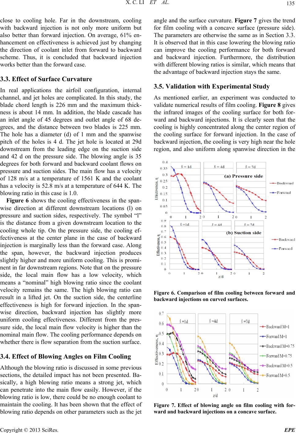 X. C. LI ET AL. 135 close to cooling hole. Far in the downstream, cooling with backward injection is not only more uniform but also better than forward injection. On average, 61% en- hancement on effectiveness is achieved just by changing the direction of coolant inlet from forward to backward scheme. Thus, it is concluded that backward injection works better than the forward case. 3.3. Effect of Surface Curvature In real applications the airfoil configuration, internal channel, and jet holes are complicated. In this study, the blade chord length is 226 mm and the maximum thick- ness is about 14 mm. In addition, the blade cascade has an inlet angle of 45 degrees and outlet angle of 68 de- grees, and the distance between two blades is 225 mm. The hole has a diameter (d) of 1 mm and the spanwise pitch of the holes is 4 d. The jet hole is located at 29d downstream from the leading edge on the suction side and 42 d on the pressure side. The blowing angle is 35 degrees for both forward and backward coolant flows on pressure and suction sides. The main flow has a velocity of 128 m/s at a temperature of 1561 K and the coolant has a velocity is 52.8 m/s at a temperature of 644 K. The blowing ratio in this case is 1.0. Figure 6 shows the cooling effectiveness in the span- wise direction at different downstream locations (l) on pressure and suction sides, respectively. The symbol “l” is the distance from a given downstream location to the cooling whole tip. On the pressure side, the cooling ef- fectiveness at the center plane in the case of backward injection is marginally less than the forward case. Along the span, however, the backward injection produces slightly higher and more uniform cooling. This is promi- nent in far downstream regions. Note that on the pressure side, the local main flow has a low velocity, which means a “nominal” high blowing ratio since the coolant velocity remains the same. The high blowing ratio can result in a lifted jet. On the suction side, the centerline effectiveness is high for forward injection. In the span- wise direction, backward injection has slightly more uniform cooling effectiveness. Different from the pres- sure side, the local main flow velocity is higher than the nominal main flow. The cooling performance depends on whether there is flow separation from the suction surface. 3.4. Effect of Blowing Angles on Film Cooling Although the blowing ratio is discu ssed in some prev ious sections, the detailed impact has not been presented. Ba- sically, a high blowing ratio means a strong jet, which can penetrate into the main flow easily. However, if the blowing ratio is low, there could be no enough coolant to maintain the coo ling. It has been shown that the effect of blowing ratio depends on other parameters such as the jet angle and the surface curvature. Figure 7 gives the trend for film cooling with a concave surface (pressure side). The par ameters are other wise the same as in S ection 3.3. It is observed that in this case lo wering the blowing ratio can improve the cooling performance for both forward and backward injection. Furthermore, the distribution with different blowing ratios is similar, which means that the advantage of backward injection stays the same. 3.5. Validation with Experimental Study As mentioned earlier, an experiment was conducted to validate numerical results of film cooling . Figure 8 gives the infrared images of the cooling surface for both for- ward and backward injections. It is clearly seen that the cooling is highly concentrated along the center region of the cooling surface for forward injection. In the case of backward injection, the coo ling is very high near the hole region, and also uniform along spanwise direction in the Figure 6. Comparison of film cooling between forward and backward injections on curved surfaces. Figure 7. Effect of blowing angle on film cooling with for- ward and backward injections on a concave surface. Copyright © 2013 SciRes. EPE 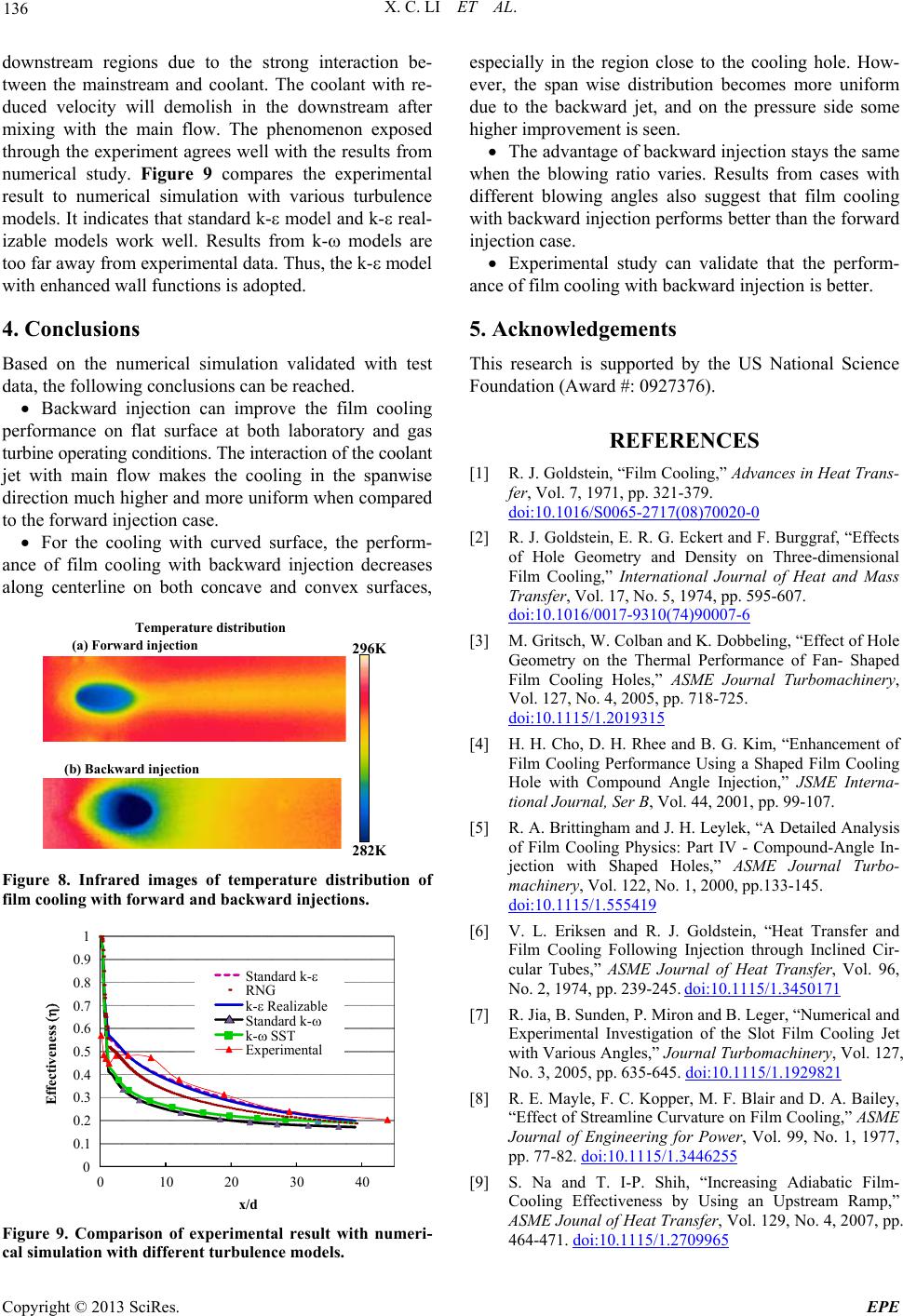 X. C. LI ET AL. 136 downstream regions due to the strong interaction be- tween the mainstream and coolant. The coolant with re- duced velocity will demolish in the downstream after mixing with the main flow. The phenomenon exposed through the experiment agrees well with the results from numerical study. Figure 9 compares the experimental result to numerical simulation with various turbulence models. It indicates that standard k- model and k- real- izable models work well. Results from k- models are too far away from experimental data. Thus, the k- model with enhanced wall functions is adopted. 4. Conclusions Based on the numerical simulation validated with test data, the following conclusions can be reached. Backward injection can improve the film cooling performance on flat surface at both laboratory and gas turbine operating conditions. The interaction of the coolant jet with main flow makes the cooling in the spanwise direction much higher and more uniform when compared to the forward injection case. For the cooling with curved surface, the perform- ance of film cooling with backward injection decreases along centerline on both concave and convex surfaces, 296 K Temperature distribution 282 K (a) For wa r d injection ( b ) Backwar d in j ection Figure 8. Infrared images of temperature distribution of film cooling with forward and backward injections. Effectiveness 0 0.1 0.2 0.3 0.4 0.5 0.6 0.7 0.8 0.9 1 0 102030 40 Standard k- RNG k- Realizable Standard k- k- SST Experimental x/d Figure 9. Comparison of experimental result with numeri- cal simulation with different turbulence models. especially in the region close to the cooling hole. How- ever, the span wise distribution becomes more uniform due to the backward jet, and on the pressure side some higher improvement is seen. The advantage of backward injection stays the same when the blowing ratio varies. Results from cases with different blowing angles also suggest that film cooling with backward injection p erforms better than the forward injection case. Experimental study can validate that the perform- ance of film cooling with backward injection is better. 5. Acknowledgements This research is supported by the US National Science Foundation (Award #: 0927376). REFERENCES [1] R. J. Goldstein, “Film Cooling,” Advances in Heat Trans- fer, Vol. 7, 1971, pp. 321-379. doi:10.1016/S0065-2717(08)70020-0 [2] R. J. Goldstein, E. R. G. Eckert and F. Burggraf, “Effects of Hole Geometry and Density on Three-dimensional Film Cooling,” International Journal of Heat and Mass Transfer, Vol. 17, No. 5, 1974, pp. 595-607. doi:10.1016/0017-9310(74)90007-6 [3] M. Gritsch, W. Colban and K. Dobbeling, “Effect of Hole Geometry on the Thermal Performance of Fan- Shaped Film Cooling Holes,” ASME Journal Turbomachinery, Vol. 127, No. 4, 2005, pp. 718-725. doi:10.1115/1.2019315 [4] H. H. Cho, D. H. Rhee and B. G. Kim, “Enhancement of Film Cooling Performance Using a Shaped Film Cooling Hole with Compound Angle Injection,” JSME Interna- tional Journal, Ser B, Vol. 44, 2001, pp. 99-107. [5] R. A. Brittingham and J. H. Leylek, “A Detailed Analysis of Film Cooling Physics: Part IV - Compound-Angle In- jection with Shaped Holes,” ASME Journal Turbo- machinery, Vol. 122, No. 1, 2000, pp.133-145. doi:10.1115/1.555419 [6] V. L. Eriksen and R. J. Goldstein, “Heat Transfer and Film Cooling Following Injection through Inclined Cir- cular Tubes,” ASME Journal of Heat Transfer, Vol. 96, No. 2, 1974, pp. 239-245. doi:10.1115/1.3450171 [7] R. Jia, B. Sunden, P. Miron and B. Leger, “Numerical and Experimental Investigation of the Slot Film Cooling Jet with Various Angles,” Journal Turbomachinery, Vol. 127, No. 3, 2005, pp. 635-645. doi:10.1115/1.1929821 [8] R. E. Mayle, F. C. Kopper, M. F. Blair and D. A. Bailey, “Effect of Streamline Curvature on Film Cooling,” ASME Journal of Engineering for Power, Vol. 99, No. 1, 1977, pp. 77-82. doi:10.1115/1.3446255 [9] S. Na and T. I-P. Shih, “Increasing Adiabatic Film- Cooling Effectiveness by Using an Upstream Ramp,” ASME Jounal of Heat Transfer, Vol. 129, No. 4, 2007, pp. 464-471. doi:10.1115/1.2709965 Copyright © 2013 SciRes. EPE  X. C. LI ET AL. Copyright © 2013 SciRes. EPE 137 [10] Y. Lu, A. Dhungel, S. V. Ekkad and R. S. Bunker, “Ef- fect of Trench Width and Depth on Film Cooling from Cylindrical Holes Embedded in Trenches,” Journal of Turbomachinery, Vol. 131, 2009, pp. 011003- 011113. [11] X. Li and T. Wang, “Simulation of Film Cooling En- hancement with Mist Injection,” ASME Journal of Heat Transfer, Vol. 128, No.6, 2006, pp. 509-519. doi:10.1115/1.2171695 [12] X. Li and T. Wang, “Computational Analysis of Surface Curvature Effect on Mist Film Cooling Performance,” Journal Heat Transfer, Vol. 130, 2008, pp. 121901-1219 10. [13] X. Li, “Numerical Simulation on Fluid Flow and Heat Transfer of Film Cooling with Backward Injection,” Pro- ceedings of 14th Internatinal Heat Transfer Conference, Washington DC, 2010, pp. 257-265. |