

Paper Menu >>
Journal Menu >>
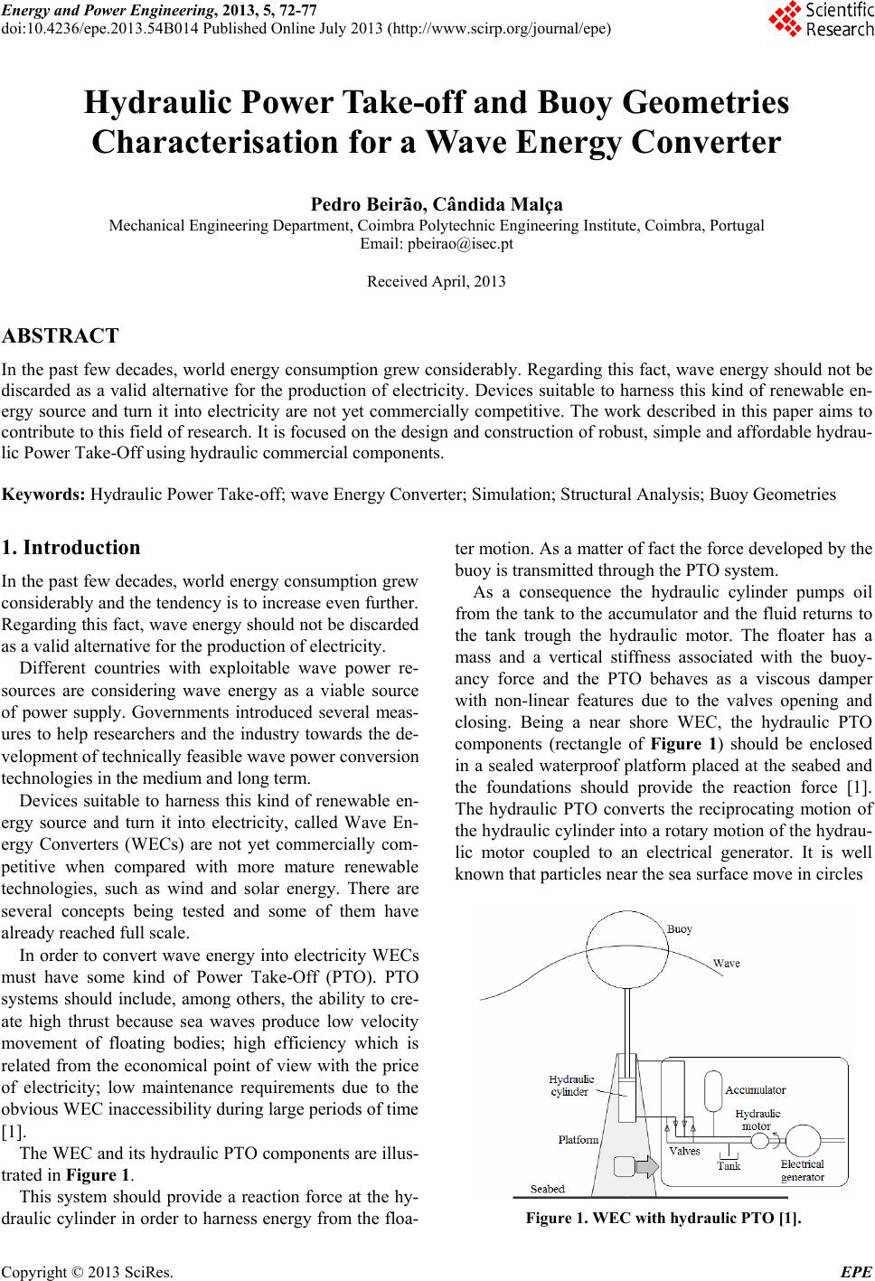 Energy and Power Engineering, 2013, 5, 72-77 doi:10.4236/epe.2013.54B014 Published Online July 2013 (http://www.scirp.org/journal/epe) Hydraulic Power Take-off and Buoy Geometries Characterisation for a Wave Energy Converter Pedro Beirão, Cândida Malça Mechanical Engineering Department, Coimbra Polytechnic Engineering Institute, Coimbra, Portugal Email: [email protected] Received April, 2013 ABSTRACT In the past few decades, world energy consumption grew considerably. Regarding this fact, wave energy should not be discarded as a valid alternative for the production of electricity. Devices suitable to harness this kind of renewable en- ergy source and turn it into electricity are not yet commercially competitive. The work described in this paper aims to contribute to this field of research. It is focused on the design and construction of robust, simple and affordable hydrau- lic Power Take-Off using hydraulic commercial components. Keywords: Hydraulic Power Take-off; wave Energy Converter; Simulation; Structural Analysis; Buoy Geometries 1. Introduction In the past few decades, world energy consumption grew consider ably and th e tenden cy is to incr ease ev en furthe r. Regarding this fact, wave energy should not be discarded as a valid alternative for the production of electricity. Different countries with exploitable wave power re- sources are considering wave energy as a viable source of power supply. Governments introduced several meas- ures to help researchers and the industry towards the de- velopment of technically feasible wave power conversion technologies in the medium and long term. Devices suitable to harness this kind of renewable en- ergy source and turn it into electricity, called Wave En- ergy Converters (WECs) are not yet commercially com- petitive when compared with more mature renewable technologies, such as wind and solar energy. There are several concepts being tested and some of them have already reached full scale. In order to convert wave energy into electricity WECs must have some kind of Power Take-Off (PTO). PTO systems should include, among others, the ability to cre- ate high thrust because sea waves produce low velocity movement of floating bodies; high efficiency which is related from the economical point of view with the price of electricity; low maintenance requirements due to the obvious WEC inaccessibility during large periods of time [1]. The WEC and its hydraulic PTO components are illus- trated in Figure 1. This system should provide a reaction force at the hy- draulic cylinder in order to harness energy from the floa- ter motion. As a matter of fact the force developed by the buoy is transmitted through the PTO system. As a consequence the hydraulic cylinder pumps oil from the tank to the accumulator and the fluid returns to the tank trough the hydraulic motor. The floater has a mass and a vertical stiffness associated with the buoy- ancy force and the PTO behaves as a viscous damper with non-linear features due to the valves opening and closing. Being a near shore WEC, the hydraulic PTO components (rectangle of Figure 1) should be enclosed in a sealed waterproof platform placed at the seabed and the foundations should provide the reaction force [1]. The hydraulic PTO converts the reciprocating motion of the hydraulic cylind er into a rotary motion of th e hydrau- lic motor coupled to an electrical generator. It is well known that particles near the sea surface move in circles Figure 1. WEC with hydraulic PTO [1]. Copyright © 2013 SciRes. EPE 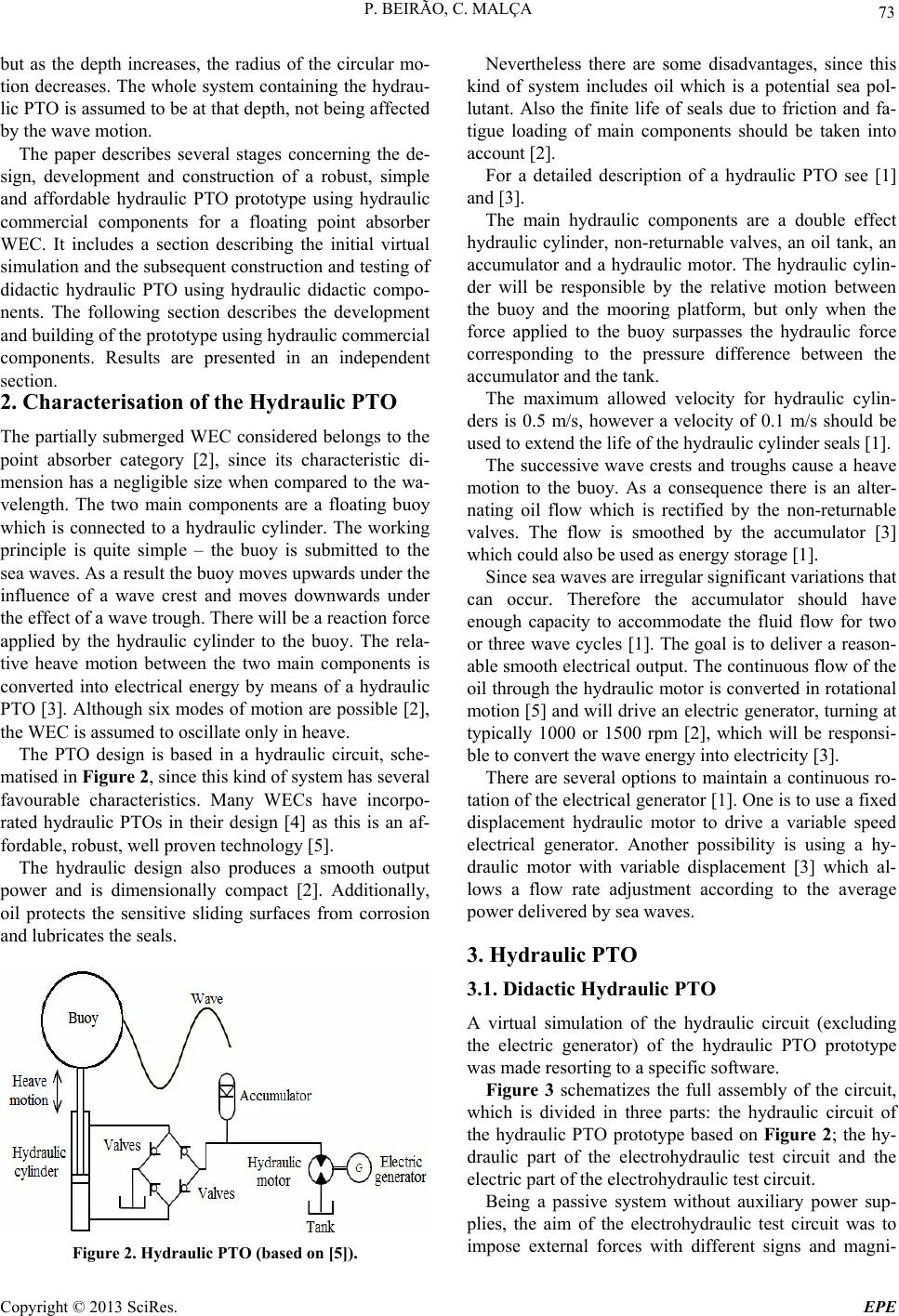 P. BEIRÃO, C. MALÇA 73 but as the depth increases, the radius of the circular mo- tion decreases. The whole system containing the hydrau- lic PTO is assumed to be at that depth, not being affected by the wave motion. The paper describes several stages concerning the de- sign, development and construction of a robust, simple and affordable hydraulic PTO prototype using hydraulic commercial components for a floating point absorber WEC. It includes a section describing the initial virtual simulation and the subsequ ent construction and testing of didactic hydraulic PTO using hydraulic didactic compo- nents. The following section describes the development and building of the prototype using hydraulic commercial components. Results are presented in an independent section. 2. Characterisation of the Hydraulic PTO The partially submerged WEC considered belongs to the point absorber category [2], since its characteristic di- mension has a negligible size when compared to the wa- velength. The two main components are a floating buoy which is connected to a hydraulic cylinder. The working principle is quite simple – the buoy is submitted to the sea waves. As a result the buoy moves upwards under the influence of a wave crest and moves downwards under the effect of a wave trough. There will be a reaction force applied by the hydraulic cylinder to the buoy. The rela- tive heave motion between the two main components is converted into electrical energy by means of a hydraulic PTO [3]. Although six modes of motion are possible [2], the WEC is assumed to oscillate only in heave. The PTO design is based in a hydraulic circuit, sche- matised in Figure 2, since this kind of system has several favourable characteristics. Many WECs have incorpo- rated hydraulic PTOs in their design [4] as this is an af- fordable, robust, well proven technology [5]. The hydraulic design also produces a smooth output power and is dimensionally compact [2]. Additionally, oil protects the sensitive sliding surfaces from corrosion and lubricates the seals. Figure 2. Hydraulic PTO (based on [5]). Nevertheless there are some disadvantages, since this kind of system includes oil which is a potential sea pol- lutant. Also the finite life of seals due to friction and fa- tigue loading of main components should be taken into account [2]. For a detailed description of a hydraulic PTO see [1] and [3]. The main hydraulic components are a double effect hydraulic cylinder, non-returnable valves, an oil tank, an accumulator and a hydraulic motor. The hydraulic cylin- der will be responsible by the relative motion between the buoy and the mooring platform, but only when the force applied to the buoy surpasses the hydraulic force corresponding to the pressure difference between the accumulator and the tank. The maximum allowed velocity for hydraulic cylin- ders is 0.5 m/s, however a velocity of 0.1 m/s should be used to extend the life of the hydraulic cylinder seals [1]. The successive wave crests and troughs cause a heave motion to the buoy. As a consequence there is an alter- nating oil flow which is rectified by the non-returnable valves. The flow is smoothed by the accumulator [3] which could also be used as energy storage [1]. Since sea waves are irregular significant variations that can occur. Therefore the accumulator should have enough capacity to accommodate the fluid flow for two or three wave cycles [1]. The goal is to deliver a reason- able smooth electrical outpu t. The continuous f low of the oil through the hydr aulic motor is converted in rotational motion [5] and will drive an electric g enerator, turning at typically 1000 or 1500 rpm [2], which will be responsi- ble to convert the wave energy into electricity [3]. There are several options to maintain a continuous ro- tation of the electrical generator [1]. One is to use a fixed displacement hydraulic motor to drive a variable speed electrical generator. Another possibility is using a hy- draulic motor with variable displacement [3] which al- lows a flow rate adjustment according to the average power del ivered by sea w aves. 3. Hydraulic PTO 3.1. Didactic Hydraulic PTO A virtual simulation of the hydraulic circuit (excluding the electric generator) of the hydraulic PTO prototype was made resorting to a specific software. Figure 3 schematizes the full assembly of the circuit, which is divided in three parts: the hydraulic circuit of the hydraulic PTO prototype based on Figure 2; the hy- draulic part of the electrohydraulic test circuit and the electric part of the electrohydraulic test circuit. Being a passive system without auxiliary power sup- plies, the aim of the electrohydraulic test circuit was to impose external forces with different signs and magni- Copyright © 2013 SciRes. EPE 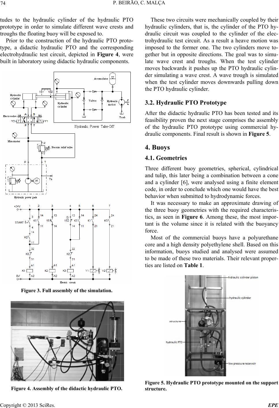 P. BEIRÃO, C. MALÇA 74 tudes to the hydraulic cylinder of the hydraulic PTO prototype in order to simulate different wave crests and troughs the floating buoy will be exposed to. Prior to the construction of the hydraulic PTO proto- type, a didactic hydraulic PTO and the corresponding electrohydraulic test circuit, depicted in Figure 4, were built in laboratory using didactic hydraulic components. Figure 3. Full assembly of the simulation. Figure 4. Assembly of the didact ic hydraulic PTO. These two circuits were mechanically coupled by their hydraulic cylinders, that is, the cylinder of the PTO hy- draulic circuit was coupled to the cylinder of the elec- trohydraulic test circuit. As a result a heave motion was imposed to the former one. The two cylinders move to- gether but in opposite directions. The goal was to simu- late wave crest and troughs. When the test cylinder moves backwards it pushes up the PTO hydraulic cylin- der simulating a wave crest. A wave trough is simulated when the test cylinder moves downwards pulling down the PTO hydraulic cylinder. 3.2. Hydraulic PTO Prototype After the didactic hydraulic PTO has been tested and its feasibility proven the next stage comprises the assembly of the hydraulic PTO prototype using commercial hy- draulic components. Final result is shown in Figure 5. 4. Buoys 4.1. Geometries Three different buoy geometries, spherical, cylindrical and tulip, this later being a combination between a cone and a cylinder [6], were analysed using a finite element code, in order to conclude which one would have the best behavior when submitted to hydrodynamic forces. It was necessary to make an approximate drawing of the three buoy geometries with the required characteris- tics, as seen in Figure 6. Among these, the most impor- tant is the volume since it is related with the buoyancy force. Most of the commercial buoys have a polyurethane core and a high density polyethylene shell. Based on this information, buoys studied and analysed were assumed to be made of these two materials. Their relevant proper- ties are listed on Table 1. Figure 5. Hydraulic PTO prototype mounted on the support structure. Copyright © 2013 SciRes. EPE 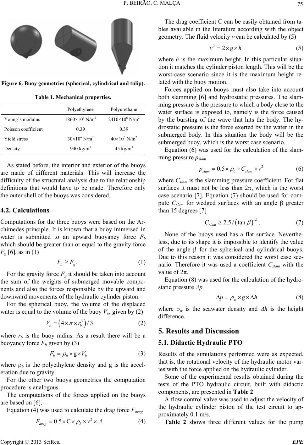 P. BEIRÃO, C. MALÇA 75 Figure 6. Buoy geometries (spherical, cylindrical and tulip). Table 1. Mechanical properties. Polyethylene Polyurethane Young’s modulus 1860×106 N/m2 2410×106 N/m2 Poisson coefficient 0.39 0.39 Yield stress 30×106 N/m2 40×106 N/m2 Density 940 kg/m3 45 kg/m3 As stated before, the interior and exterior of the buoys are made of different materials. This will increase the difficulty of the structural analysis due to the relationship definitions that would have to be made. Therefore only the outer shell of the buoys was consid ered. 4.2. Calculations Computations for the three buoys were based on the Ar- chimedes principle. It is known that a buoy immersed in water is submitted to an upward buoyancy force Fb which should be greater than or equal to the gravity force Fg [6], as in (1) . bg F F (1) For the gr avity for ce Fg it should be taken into account the sum of the weights of submerged movable compo- nents and also the forces responsible by the upward and downward movements of the hydraulic cylinder piston. For the spherical buoy, the volume of the displaced water is equal to the volume of the buoy Vb, given by (2) 3 4 bb Vr /3 b (2) where rb is the buoy radius. As a result there will be a buoyancy force Fb given by (3) g bb F V (3) where b is the polyethylene density and g is the accel- eration due to gravity. For the other two buoys geometries the computation procedure is analogous. The computations of the forces applied on the buoys are based on [6]. Equation (4) was used to calculate the drag force Fdrag 2 0.5 C drag b F vA (4) The drag coefficient C can be easily obtained from ta- bles available in the literature according with the object geometry. The fluid velocity v can be calculated by (5) 22gvh (5) where h is the maximum height. In this particular situa- tion it matches the cylinder piston length. This will be the worst-case scenario since it is the maximum height re- lated with the buoy motion. Forces applied on buoys must also take into account both slamming [6] and hydrostatic pressures. The slam- ming pressure is the pressure to which a body close to the water surface is exposed to, namely is the force caused by the bursting of the wave that hits the body. The hy- drostatic pressure is the force exerted by the water in the submerged body. In this situation the body will be the submerged buoy, which is the worst case scenario. Equation (6) was used for the calculation of the slam- ming pressure pslam 2 0.5 slamb slam pC v (6) where Cslam is the slamming pressure coefficient. For flat surfaces it must not be less than 2, which is the worst case scenario [7]. Equation (7) should be used for com- pute Cslam for wedged surfaces with an angle greater than 15 degrees [7] 1.1 2.5/ tan. slam C (7) None of the buoys used has a flat surface. Neverthe- less, due to its shape it is impossible to identify the value of the angle for the spherical and cylindrical buoys. Due to this reason it was considered the worst case sce- nario. Therefore it was used a coefficient Cslam with the value of 2. Equation (8) was used for the calculation of the hydro- static pressure p g w ph (8) where w is the seawater density and h is the height difference. 5. Results and Discussion 5.1. Didactic Hydraulic PTO Results of the simulations performed were as expected, that is, the rotational velocity of the hydraulic motor var- ies with the force applied on the hydraulic cylinder. Some of the experimental results obtained during the tests of the PTO hydraulic circuit, built with didactic components, are presented in Table 2. A flow control valve was used to adjust the velocity of the hydraulic cylinder piston of the test circuit to ap- proximately 0.1 m/s. Table 2 shows three different values for the pump Copyright © 2013 SciRes. EPE  P. BEIRÃO, C. MALÇA 76 pressure. However the remaining values are quite the same. This is due to the effect of the flow control valve. The differences of the values registered in the forward and backward strokes arise from the fact that both cylin- ders are asymmetrical. The rotational velocity of the hydraulic motor of the didactic hydraulic PTO was measured using a portable tachometer. The role of the accumulator was also tested by chang- ing the adjustment of its pressure relief valve. When ad- justed to a lower value the oil flowed to the low pressure reservoir. When increasing the opening value of the pressure relief valve the oil was kept inside the accumu- lator. During the tests performed it was found that the low pressure reservoir should be pressurized (2 bar) with compressed air. This led to an improvement of the oil flow inside the PTO hydraulic circuit and also to an in- crease of the rotational velocity of the hydraulic motor. Additionally it would prevent the presence of cavitation in the hydraulic circuit [3]. 5.2. Buoys From Figure 7 it is seen that values are bounded and none inconsistency was noticed, both at the places of greater displacement, either at the points where are ap- plied the maximum stresses and forces. It was found that maximum stress (15.5 N/mm2) never exceeded the mate- rial stress. A maximum displacement of 32.61 mm is located at the top of the buoy. A safety factor of 1.90 was obtained in the docking of the buoy. According with Figure 8 it is seen that this geometry would be subject to a minor stress, since maximum stress (15.14 N/mm2) is lower than the obtained with the spherical buoy. A maximum displacement of 20.51 mm is located at the top of the buoy. A safety factor of 1.95 was obtained in the docking of the buoy. Concerning the tulip buoy geometry shown in Figure 9 it can be observed that this buoy geometry is the best one regarding the request that is submitted to. The max- imum stress (13.37 N/mm2) is the lowest of the three buoys. It was obtained a maximum displacement of 33.51 mm, located on top of the buoy. A safety factor of 2.21 was obtained in the docking of the buoy. Table 2. Test results. Velocity PTO hydraulic cylinder Pressure forward backward PTO hydraulic motor 20 N/m2 0.073 m/s 0.14 m/s 110 rpm 25 N/m2 0.081 m/s 0.13 m/s 110 rpm 30 N/m2 0.078 m/s 0.15 m/s 110 rpm Figure 7. Spherical buoy structural analysis. Figure 8. Cylindrical buoy structural analysis. Figure 9. Tulip buoy structural analysis. Copyright © 2013 SciRes. EPE  P. BEIRÃO, C. MALÇA Copyright © 2013 SciRes. EPE 77 6. Conclusions Results were obtained by means of simulation of the PTO hydraulic circuit using specific software and a di- dactic hydraulic PTO specially built for this purpose. It was possible to demonstrate the working principle of the hydraulic PTO using didactic components. A hydraulic PTO prototype was built using commercial hydraulic components mounted on a steel support structure. In order to understand the WEC behavior when sub- mitted to simulated wave forces, structural calculations were done resorting to a finite element code. Until attaining the final stage there are yet many prob- lems to surpass and some aspects to develop and improve, namely the coupling between the buoy and the hydraulic cylinder piston using a kinetic joint; the pressurization of the oil reservoir through a compressor powered by the system; the sizing of the rotary electric generator that should be coupled to the hydraulic motor; the sealing of the hydraulic PTO by means of a enclosure that should also serve as a mooring base put at the sea bottom near shore and the test of the whole system performed in a wave tank or at real sea conditions. REFERENCES [1] E. Spooner and M. Mueller, “Comparative Study of Lin- ear Generators and Hydraulic Systems for Wave Energy Conversion,” ETSU V/06/00189/REP, DTI/Pub URN 01/783, United Kingdom, 2001. http://www.tridentenergy.co.uk/pdf/DTI%20Report.pdf [2] J. Falnes, “A Review of Wave-energy Extraction,” Ma- rine Structures, Vol. 20, No. 4, 2007, pp. 185-F201. doi:10.1016/j.marstruc.2007.09.001 [3] A. Falcão. “Wave Energy Utilization: A Review of the Technologies,” Renewable and Sustainable Energy Re- views, Vol. 14, No. 3, 2010, pp. 899-918. doi:10.1016/j.rser.2009.11.003 [4] R. Henderson, “Design, Simulation, and Testing of a Novel Hydraulic Power Take-off System for the Pelamis Wave Energy Converter, “ Renewable Energy, Vol. 31, No. 2, 2006, pp. 271-283. doi:10.1016/j.renene.2005.08.021 [5] G. Bacelli, J. Gilloteaux and J. Ringwood, “State Space Model of a Hydraulic Power Take off unit for Wave En- ergy Conversion Employing Bondgraphs,” Proceedings of the World Renewable Energy Conference, Glasgow, July 2008, pp. 1-4. [6] C. Blommaert,” Composite Floating 'Point Absorbers' for Wave Energy Converters: Survivability Design, Produc- tion Method and Large-Scale Testing,” PhD thesis, Ghent University, Ghent, 2009. [7] D. N. Veritas, “Environmental Conditions and Environ- mental Loads,” Classification Notes, 30.5’, 2000. http://www.dnv.com. |