

Paper Menu >>
Journal Menu >>
 Energy and Power Engineering, 2013, 5, 68-71 doi:10.4236/epe.2013.54B013 Published Online July 2013 (http://www.scirp.org/journal/epe) Research on Harmonic Characteristics of Nonlinear Loads in PEMFC Generator Jinquan Wang, Jianke Li, Shuhua Qian, Jingjing Chen, Jianhua Fang, Yachao Hu PLA University of Science & Technology, College of National Defense, Nanjing, China Email: [email protected] Received April, 2013 ABSTRACT Hydrogen as a clean energy source is made full use, this paper researches the electrical model of PEMFC generator, analyzes the harmonic trend and its hazards when the generator operates with linear load and nonlinear load running synchronously, comparatively analyzes the commonly used harmonic suppression technology. Simulate and analyze the filter performance when APF is used. The results illustrate that as a filter device, APF can absorb the harmonic properly in PEMFC power system. Keywords: PEMFC Generator; Nonlinear Load; Harmonic Flow; Filter Device 1. Introduction Because of the advantages of non-polluting, high effi- ciency, no noise, Hydrogen PEMFC generator has very broad application prospects in the civilian spheres, with- out “Carnot” cycle limit, with low working temperature, small heat radiation. Due to the need for energy conser- vation or engineering practice, the load contains a lot of power electronics, such as controlled rectifier, inverter, which resulting in harmonics and increasing the nonlin- ear components of the power supply system. The har- monic current and voltage were coupled to each other, thus increasing the difficulty of suppression of harmonic currents. This grid is often low tension and close trans- mission. It is usually chosen cable to reduce the possibil- ity of to suffer lightning and external damage. However, the high-order harmonics may not only result in resonant, causing overvoltage on the line, but also make the volt- age waveform spikes appear to accelerate the aging of the cable insulation. The harmonic pollution even affects the stability and usage of the power supply[1-2]. 2. PEMFC Generator Model 2.1. Dynamic Output Characteristics of the PEMFC Generator Due to the limited capacity of the PEMFC generator, a sudden change of the load has greater impact on the operating state of generator. In order to describe the characteristics of the generator accurately, we researched the electrical characteristics of the PEMFC generator when the load has a sudden increase and sudden reduction. The PEMFC generator dynamic characteristic curves are shown in Figure 1 and Figure 2 by the experiment. According to the PEMFC hydrogen generator output voltage waveform, due to the influence of changes in the external load, the generator output voltage amplitude variation is large. Especially, when the load is increased suddenly, the instantaneous voltage drop is very serious. Such changes usually greatly exceeded the allowed range of variation of the input voltage of the power conversion apparatus. When a sudden increase in load, the in- stantaneous voltage drop instantaneously, and the DC / AC converter is self-protecting and stop working. 2.2. PEMFC Generator Electrical Model The PEMFC generator as a power source, three electrical models, start-up model, running the model, and downtime model are considered. Studies made in this article are a dynamic process, and here is running the model. The 012345 0 10 20 30 40 50 60 70 80 90 Time(s) Figure 1. DC load operating sudde nly (0 to 4.7 kw). Copyright © 2013 SciRes. EPE 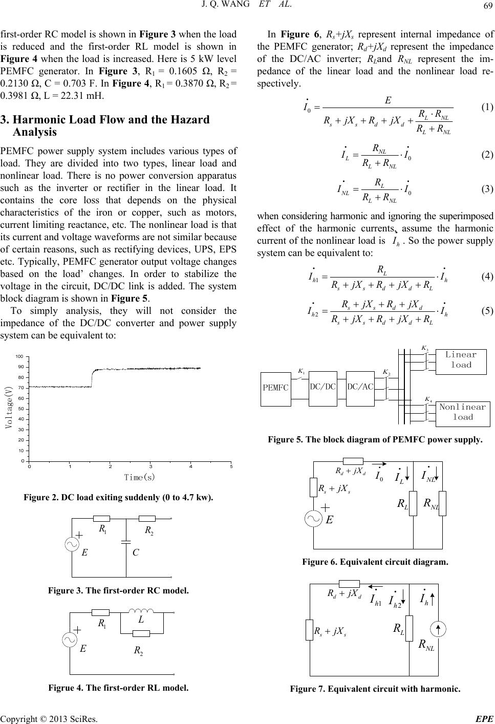 J. Q. WANG ET AL. 69 first-order RC model is shown in Figure 3 when the load is reduced and the first-order RL model is shown in Figure 4 when the load is increased. Here is 5 kW level PEMFC generator. In Figure 3, R1 = 0.1605 Ω, R2 = 0.2130 Ω, C = 0.703 F. In Figure 4, R1 = 0.3870 Ω, R2 = 0.3981 Ω, L = 22.31 mH. 3. Harmonic Load Flow and the Hazard Analysis PEMFC power supply system includes various types of load. They are divided into two types, linear load and nonlinear load. There is no power conversion apparatus such as the inverter or rectifier in the linear load. It contains the core loss that depends on the physical characteristics of the iron or copper, such as motors, current limiting reactance, etc. The nonlinear load is that its current and voltage waveforms are not similar because of certain reasons, such as rectifying devices, UPS, EPS etc. Typically, PEMFC generator output voltage changes based on the load’ changes. In order to stabilize the voltage in the circuit, DC/DC link is added. The system block diagram is shown in Figure 5. To simply analysis, they will not consider the impedance of the DC/DC converter and power supply system can be equivalent to: Figure 2. DC load exiting suddenly (0 to 4.7 kw). E 1 R 2 R C Figure 3. The first-order RC model. E 1 R 2 R L Figrue 4. The first-order RL model. In Figure 6, Rs+jXs represent internal impedance of the PEMFC generator; Rd+jXd represent the impedance of the DC/AC inverter; RLand RNL represent the im- pedance of the linear load and the nonlinear load re- spectively. 0 L NL ssdd L NL E IRR RjXRjXRR (1) 0 NL LLNL R I I RR (2) 0 L NL LNL R I I RR (3) when considering harmonic and ignoring the superimposed effect of the harmonic currents, assume the harmonic current of the nonlinear load is h I . So the power supply system can be equivalent to: 1 L hh ssddL R I I RjXRjXR (4) 2 ssdd hh ssddL RjXRjX I I RjXRjXR (5) 1 K 2 K 4 K 3 K Figure 5. The block diagram of P EMFC power supply. L R NL R L I NL I E s s R jX dd R jX 0 I Figure 6. Equivalent circuit diagram. L R NL R 2h I h I s s R jX dd R jX 1h I Figure 7. Equivalent circuit with harmonic. Copyright © 2013 SciRes. EPE  J. Q. WANG ET AL. 70 Learn from the harmonic load flow, the harmonic, which sends out by the nonlinear load, may flow to the linear slip and the power bus. When harmonic flowing through the line, for the frequency characteristic, the line resistance may increase with the frequency. Acting under the skin effect, the harmonic current increases the addi- tional loss in the line. The harmonics can also make harm to the rotary electric machine through the additional loss and torque, due to the affection of skin effect, hysteresis and eddy, the additional loss in the iron and windings of the rotary electric machine would increase with the in- crease of the frequency [3-5] . 4. Method for Harmonic Suppression 4.1. Method for Harmonic Suppression Currently, filter is the main method to suppress the har- monic in power system. Filter which immediately ab- sorbs the generated harmonic current produced by har- monic sources is the effective method for harmonic sup- pression. Usually, the power filter can be divided into two kinds, passive and active power filter. Passive Power Filter(PPF) is configured in accordance with certain elements such as capacitance, inductance and resistance, and connected in a certain topology. It is simple in structure, low in price, and high reliability when operating. What’s more, it may also compensate reactive power and improve power factor on the basis of absorb harmonics. The PPF is widely used as a harmonic suppression device for its easy maintenance and its mature technology design and manufacture experience. A typical single tunable filter is shown in Figure 8(a). Active power filter (APF) is based on the principle of instantaneous power theory which dynamically track load harmonic changes and are real-time filtering technology [6], and the principle is shown in Figure 8(b). As one of the strategies used for harmonic suppression in the large grid or small capacity one, the APF has some unparalleled advantages. The following advantages are concluded by theoretical study and widely use in practice [7]: 1) It can not only compensate for all the harmonics, but also inhabit the flicker and compensate reactive. n L 1 n C (a) (b) Figure 8. Schematic diagram of filter. 2) Its filter characteristic does not matter with the sys- tem impedance, and it can eliminate the risk of series or parallel syntony with the system impedance or load. 3) It has not overload problem. 4) It can automatically tracks harmonic and compen- sates the changes. 5) It has fast dynamic response. The novel combines the characteristics of the PEMFC generator power, and chooses the APF as harmonic filter device. The schematic diagram of the system is shown as follows: (Figure 9) 4.2. Simulation Study We choose MATLAB as simulation platform, and use the first-order RC model of PEMFC. Then we choose three-phase motor and rectifier as linear and nonlinear load separately. The active power filter is based on the theory of instantaneous power, then we build the simula- tion model of PEMFC generator power system, the sim- ulation results are shown as follows: As is shown in Figure 10 and Figure 11, the three- phase nonlinear load sends out the five times, seven times, 11 times, and 13th times harmonic current, and the current distortion rate is 28.39%, the current waveform has a serious distortion. The urrent-wave of compensa- tion and Current wave after filtering is shown as Figure 12 and F igure 13 respectively. Seen from Figure 14, after the using of active power filter in a separate small capacity grid, the current wave- form has significantly improved, and its harmonic distor- tion rate is reduced to 4.8%, and each harmonic content are greatly reduced. 1 K 2 K 4 K 3 K 5 K Figure 9. Diagram of APF. Figure10. Current-wave of load. Copyright © 2013 SciRes. EPE  J. Q. WANG ET AL. Copyright © 2013 SciRes. EPE 71 Figure 12. Current-wave of compensation. Figure 11. Frequency of load current. Figure 13. Current wave after filtering. Figure 14. Frequency of source current after filtering. 5. Conclusions As a clean energy source, generating electricity by hy- drogen has attracted broad attention. Accompanying with the study of PEMFC gradual thorough, this paper studies the electric model of PEMFC, and analyses the harmonic load flow and its hazards when the generator running with linear and nonlinear load, and compares the com- mon technology used to suppress harmonic. What’s more, simulate and analyze the filter performance with active filter. The results show that the using of active filter for PEMFC generator system can achieve our filter goal. REFERENCES [1] Z. Wong and H. Tu, “The Research of Development and Application about Proton Exchange Membrane Fuel Cell,” Beijing: Metallurgical Industry Press, 2002 [2] J. Q. Wang and Y. Chu, “The Determination of an Order Equivalent Circuit about PEMFC Hydrogen Generator,” Nanjing: Chinese Colleges and Universities and the Electric Power System and Its Automation Professional's 22nd Annual Conference, Vol. 10, 2006, pp. 16-17. [3] F. C. De La Rosa and Y. Zhao, “Narmonics and Power Systems,” Translation, Beijing: Mechanical Industry Press, 2009. [4] K. Qian, Y. Yuan and X. Shi, et al., “Environmental Benefits Analysis of Distributed Generation,” Proceed- ings of the CSEE, Vol. 28, No. 29, 2008, pp. 11-15. [5] W. Hu, “Research on Improving Harmonic Detection Algorithm Based on Instantaneous Power of Idle Work,” Electrical Measurement & Instrumentation, Vol. 46, No. 3, 2009, pp. 6-10. [6] J. X. Meng, X. H. Lin and G. H. Shen, “Research on Power Electronics System Harmonic Interference Suppression Methods,” The Academic Journal of Shandong University of Science and Technology (Natural Science), Vol. 24, No. 2, 2005, pp. 52-56. [7] X. H. Wang and K. L. Lo, “New Development of Torque Analysis of Synchronous Machine,” Electric Machines and Power Systems, Vol. 25, No. 8, 1997, pp. 827-838. doi:10.1080/07313569708955778 |