

Paper Menu >>
Journal Menu >>
 Energy and Power Engineering, 2013, 5, 26-30 doi:10.4236/epe.2013.54B005 Published Online July 2013 (http://www.scirp.org/journal/epe) Research on Storage Capacity of Compressed Air Pumped Hydro Energy Storage Equipment* Jingtian Bi, Tong Jiang, Weili Chen, Xian Ma State Key Laboratory of Alternate Electrical Power, System with Renewable Energy Sources, North China Electric Power University, Beijing, China Email: [email protected] Received January, 2013 ABSTRACT Compressed air pumped hydro energy storage equipment combines compressed air energy storage technology and pumped storage technology. The water is pumped to a vessel to compress air for energy storage, and the compressed air expanses pushing water to drive the hydro turbine for power generation. The novel storage equipment saves natural gas resources, reduces carbon emission, and improves the controllability and reliability. The principle of compressed air pumped hydro energy storage is introduced and its mathematical model is built. The storage and generation process of the novel equipment is analyzed using the model. The calculation formula of the storage power is deduced in theory in different situations of isothermal and adiabatic compression. The optimal storage scheme is given when the capacity and withstand pressure of the vessel is definitive, and the max available capacity and the equipment utilization effi- ciency evaluation of the scheme is given. Keywords: Power Storage; Compressed Air Energy Storage; Hydraulic Equipment; Optimal Operation; Isothermal Process; Adiabatic Process; Equipment Utilization Efficiency 1. Introduction In recent years, as the problems of resources shortage and environment pollution become serious, the new en- ergy generation increases rapidly, especially the wind power[1]. However, compared with the traditional gen- eration, the wind power generation is characteristic of intermittence, volatility and randomness. The large scale integration of wind power will aggravate the unbalance of the supply and the demand of power grid, and the peak regulation ability of power grid is a serious obstacle to the development of the wind power[2]. Energy storage technology will provide a very effective way to solve these problems. In various energy storage technologies, the practical large scale storage only includes pumped storage and compressed air energy storage. The pumped station re- quires high geographical conditions, the long construc- tion period, the large initial investment and damages to the ecological environment. Compressed air energy stor- age (CAES) technology is a very promising energy stor- age system and attracts great attentions in the world, as it does not require strict geographical conditions and is economic[3]. Traditional CAES power station is divided into energy storage subsystem and power generation subsystem[4]. The energy storage subsystem, comprised of compressor, motor and gas chambers, converts the low-cost electrical energy to the compressed air stored in gas chambers such as caves and abandoned mines. During the peak load period, the power generation subsystem, comprised of the gas turbine, combustion chamber as well as the heater, generates power energy by the gas turbine driven by the compressed gas combustion[5]. Compare with other energy storage technologies, ad- vantages of compressed air energy storage system in- clude[6]: (1) It is suitable for the construction of large power plants (>100MW). Its storage capacity is just less than the pumped storage power station. CAES has long working time, and it can continue working for a few hours or even a few days. (2) The unit construction costs and operating costs of large-scale CAES stations are lower than the pumped storage power station. CAES has good economic effi- ciency. (3) CAES has a long lifespan, and it can store/release energy tens of thousands of times. Its efficiency can reach about 70%, which is close to the pumped storage power station. *Supported by the National High Technology Research and Develop- ment of China 863 Program (2012AA050208). Copyright © 2013 SciRes. EPE 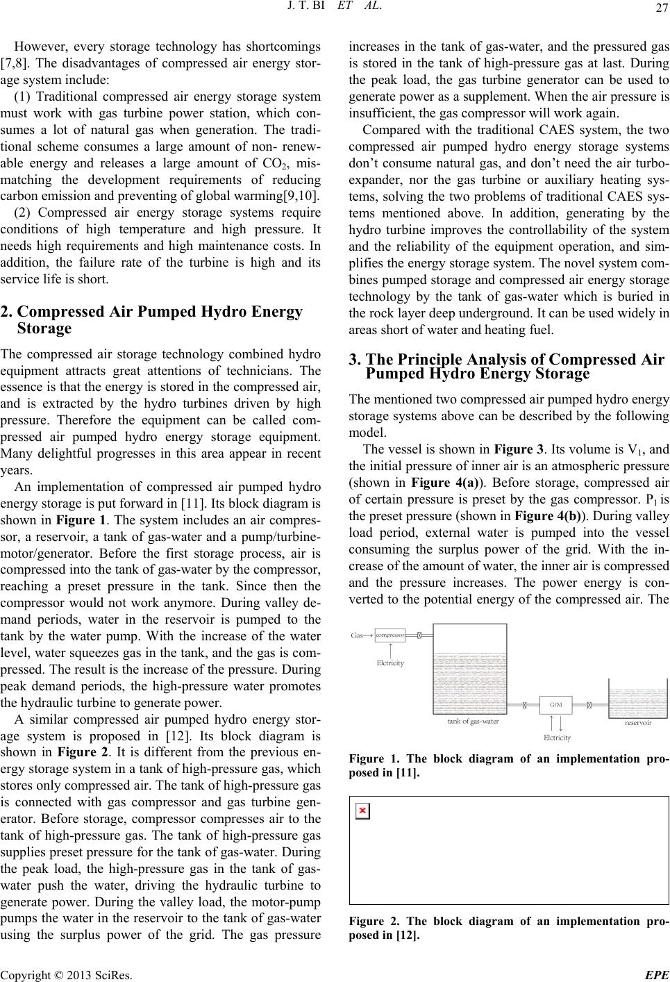 J. T. BI ET AL. 27 However, every storage technology has shortcomings [7,8]. The disadvantages of compressed air energy stor- age system include: (1) Traditional compressed air energy storage system must work with gas turbine power station, which con- sumes a lot of natural gas when generation. The tradi- tional scheme consumes a large amount of non- renew- able energy and releases a large amount of CO2, mis- matching the development requirements of reducing carbon emission and preventing of global warming[9,10]. (2) Compressed air energy storage systems require conditions of high temperature and high pressure. It needs high requirements and high maintenance costs. In addition, the failure rate of the turbine is high and its service life is short. 2. Compressed Air Pumped Hydro Energy Storage The compressed air storage technology combined hydro equipment attracts great attentions of technicians. The essence is that the energy is stored in the compressed air, and is extracted by the hydro turbines driven by high pressure. Therefore the equipment can be called com- pressed air pumped hydro energy storage equipment. Many delightful progresses in this area appear in recent years. An implementation of compressed air pumped hydro energy storage is put forward in [11]. Its block diagram is shown in Figure 1. The system includes an air compres- sor, a reservoir, a tank of gas-water and a pump/turbine- motor/generator. Before the first storage process, air is compressed into the tank of gas-water by the compressor, reaching a preset pressure in the tank. Since then the compressor would not work anymore. During valley de- mand periods, water in the reservoir is pumped to the tank by the water pump. With the increase of the water level, water squeezes gas in the tank, and the gas is com- pressed. The result is the increase of the pressure. During peak demand periods, the high-pressure water promotes the hydraulic turbine to generate power. A similar compressed air pumped hydro energy stor- age system is proposed in [12]. Its block diagram is shown in Figure 2. It is different from the previous en- ergy storage system in a tank of high-pressure gas, which stores only compressed air. The tank of high-pressure gas is connected with gas compressor and gas turbine gen- erator. Before storage, compressor compresses air to the tank of high-pressure gas. The tank of high-pressure gas supplies preset pressure for the tank of gas-water. During the peak load, the high-pressure gas in the tank of gas- water push the water, driving the hydraulic turbine to generate power. During the valley load, the motor-pump pumps the water in the reservoir to the tank of gas-water using the surplus power of the grid. The gas pressure increases in the tank of gas-water, and the pressured gas is stored in the tank of high-pressure gas at last. During the peak load, the gas turbine generator can be used to generate power as a supplement. When the air pressure is insufficient, the gas compressor will work again. Compared with the traditional CAES system, the two compressed air pumped hydro energy storage systems don’t consume natural gas, and don’t need the air turbo- expander, nor the gas turbine or auxiliary heating sys- tems, solving the two problems of traditional CAES sys- tems mentioned above. In addition, generating by the hydro turbine improves the controllability of the system and the reliability of the equipment operation, and sim- plifies the energy storage system. The novel system com- bines pumped storage and compressed air energy storage technology by the tank of gas-water which is buried in the rock layer deep underground. It can be used widely in areas short of water and heating fuel. 3. The Principle Analysis of Compressed Air Pumped Hydro Energy Storage The mentioned two compressed air pumped hydro energy storage systems above can be described by the following model. The vessel is shown in Figure 3. Its volume is V1, and the initial pressure of inner air is an atmospheric pressure (shown in Figure 4(a)). Before storage, compressed air of certain pressure is preset by the gas compressor. P1 is the preset pressure (shown in Figure 4(b)). During valley load period, external water is pumped into the vessel consuming the surplus power of the grid. With the in- crease of the amount of water, the inner air is compressed and the pressure increases. The power energy is con- verted to the potential energy of the compressed air. The Figure 1. The block diagram of an implementation pro- posed in [11]. Figure 2. The block diagram of an implementation pro- posed in [12]. Copyright © 2013 SciRes. EPE 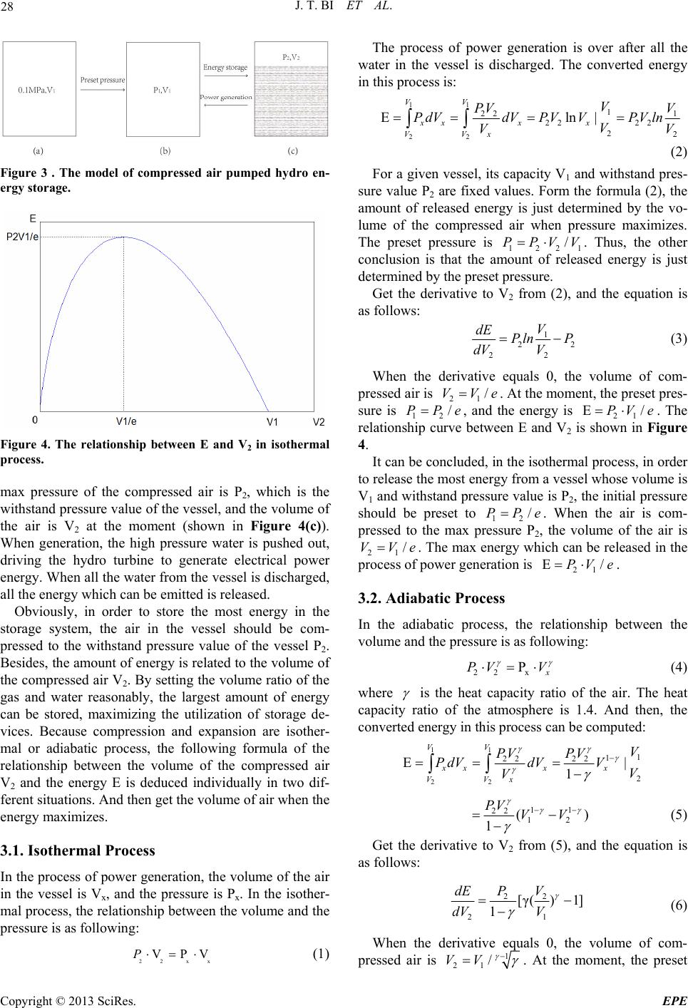 J. T. BI ET AL. 28 Figure 3 . The model of compressed air pumped hydro en- ergy storage. Figure 4. The relationship between E and V2 in isothermal process. max pressure of the compressed air is P2, which is the withstand pressure value of the vessel, and the volume of the air is V2 at the moment (shown in Figure 4(c)). When generation, the high pressure water is pushed out, driving the hydro turbine to generate electrical power energy. When all the water from the vessel is discharged, all the energy which can be emitted is released. Obviously, in order to store the most energy in the storage system, the air in the vessel should be com- pressed to the withstand pressure value of the vessel P2. Besides, the amount of energy is related to the volume of the compressed air V2. By setting the volume ratio of the gas and water reasonably, the largest amount of energy can be stored, maximizing the utilization of storage de- vices. Because compression and expansion are isother- mal or adiabatic process, the following formula of the relationship between the volume of the compressed air V2 and the energy E is deduced individually in two dif- ferent situations. And then get the volume of air when the energy maximizes. 3.1. Isothermal Process In the process of power generation, the volume of the air in the vessel is Vx, and the pressure is Px. In the isother- mal process, the relationship between the volume and the pressure is as following: 22 x VPVP The process of power generation is over after all the water in the vessel is discharged. The converted energy in this process is: 11 22 1 22 1 22 22 22 Eln| VV xxx x x VV V PV V PdVdVPV VPVln V VV (2) For a given vessel, its capacity V1 and withstand pres- sure value P2 are fixed values. Form the formula (2), the amount of released energy is just determined by the vo- lume of the compressed air when pressure maximizes. The preset pressure is 1221 /PPVV . Thus, the other conclusion is that the amount of released energy is just determined by the preset pressure. Get the derivative to V2 from (2), and the equation is as follows: 1 2 22 V dE Pln P dVV 2 (3) When the derivative equals 0, the volume of com- pressed air is 21 /VVe . At the moment, the preset pres- sure is 12 /ePP , and the energy is 21 . The relationship curve between E and V2 is shown in Figure 4. EPV e/ It can be concluded, in the isothermal process, in order to release the most energy from a vessel whose volume is V1 and withstand pressure value is P2, the initial pressure should be preset to 12 /PPe . When the air is com- pressed to the max pressure P2, the volume of the air is 21 /VVe . The max energy which can be released in the process of power generation is . 21 E/PV e 3.2. Adiabatic Process In the adiabatic process, the relationship between the volume and the pressure is as following: 22 x P x PV V (4) where is the heat capacity ratio of the air. The heat capacity ratio of the atmosphere is 1.4. And then, the converted energy in this process can be computed: 11 22 1 1 22 22 2 E| 1 VV xxx x VV x V PV PV PdVdVV V V 11 22 12 ( 1 PV VV ) (5) Get the derivative to V2 from (5), and the equation is as follows: 22 21 [γ() 1] 1 PV dE dV V (6) When the derivative equals 0, the volume of com- x (1) pressed air is 1 21 /VV . At the moment, the preset Copyright © 2013 SciRes. EPE 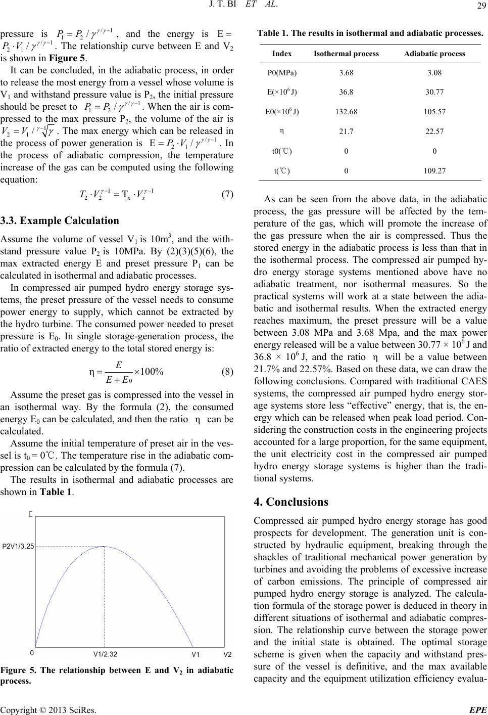 J. T. BI ET AL. 29 pressure is P/1 12 /P , and the energy is E /1 21 /PV . hip curve between E and igure 5. It can be concluded The relations F , in th V2 order is shown in to e adiabatic process, in release the most energy from a vessel whose volume is V1 and withstand pressure value is P2, the initial pressure should be preset to /1 12 /PP . When the air is com- pressed to the max pressue volume of the air is re P2, th 1 21 /VV . The max energy which can be released in power generation is /1 21 E/PV the process of . In the process of adiabatic compressture increase of the gas can be computed using the following equation: ion, the 11 x Tx V V1 is 10m3, an tempera (7) with- e sys- 22 TV ple Calculation 3.3. Exam d the g te Assume the volume of vessel stand pressure value P2 is 10MPa. By (2)(3)(5)(6), the max extracted energy E and preset pressure P1 can be calculated in isothermal and adiabatic processes. In compressed air pumped hydro energy stora ms, the preset pressure of the vessel needs to consume power energy to supply, which cannot be extracted by the hydro turbine. The consumed power needed to preset pressure is E0. In single storage-generation process, the ratio of extracted energy to the total stored energy is: 0 100% EE ed into erature of preset air η the preset gas is compress e initial temp E Assume the vessel i an hin th se sh (8) n e ves- cesses are isothermal way. By the formula (2), the consumed energy E0 can be calculated, and then the ratio η can be calculated. Assume t l is t0 = 0℃. The temperature rise in the adiabatic com- pression can be calculated by the formula (7). The results in isothermal and adiabatic pro own in Table 1. Figure 5. The in adiabatic process. relationship between E and V2 Table 1. The results in isothermal and adiabatic processes. Index Isothermal process Adiabatic process P0(MPa)3.68 3.08 E(×106 J)36.8 30.77 E0(×106 J)1 0 10 32.68 105.57 η 21.7 22.57 t0( )℃0 t( )℃ 0 9.27 As can be seen fro the above data, in the adiabatic r s ped hydro energy storage has good m pocess, the gas pressure will be affected by the tem- perature of the gas, which will promote the increase of the gas pressure when the air is compressed. Thus the stored energy in the adiabatic process is less than that in the isothermal process. The compressed air pumped hy- dro energy storage systems mentioned above have no adiabatic treatment, nor isothermal measures. So the practical systems will work at a state between the adia- batic and isothermal results. When the extracted energy reaches maximum, the preset pressure will be a value between 3.08 MPa and 3.68 Mpa, and the max power energy released will be a value between 30.77 × 10⁶ J and 36.8 × 10⁶ J, and the ratio η will be a value between 21.7% and 22.57%. Based on these data, we can draw the following conclusions. Compared with traditional CAES systems, the compressed air pumped hydro energy stor- age systems store less “effective” energy, that is, the en- ergy which can be released when peak load period. Con- sidering the construction costs in the engineering projects accounted for a large proportion, for the same equipment, the unit electricity cost in the compressed air pumped hydro energy storage systems is higher than the tradi- tional systems. 4. Conclusion Compressed air pum prospects for development. The generation unit is con- structed by hydraulic equipment, breaking through the shackles of traditional mechanical power generation by turbines and avoiding the problems of excessive increase of carbon emissions. The principle of compressed air pumped hydro energy storage is analyzed. The calcula- tion formula of the storage power is deduced in theory in different situations of isothermal and adiabatic compres- sion. The relationship curve between the storage power and the initial state is obtained. The optimal storage scheme is given when the capacity and withstand pres- sure of the vessel is definitive, and the max available capacity and the equipment utilization efficiency evalua- Copyright © 2013 SciRes. EPE  J. T. BI ET AL. Copyright © 2013 SciRes. EPE 30 ENCES [1] L. Y. Hu, “Aichnology,” Shang- hai Electric Po8-160. ower, Vol. tric Power, Vol. 30, No. 9, d On Compressed Air Energy Storage, Zhejiang Univer- d Air Energy Storage Sy ang and Z. P. Song, “Optimization and , H. S. Chen, et al., “A Novel Energy ce Analy- tion of the scheme is given. REFER r Storage Generation Te wer, Vol. 2, 2006, pp. 15 [2] L. Ye, “Study on Sustainable Development Strategy of Electric Power in China in 2020,” Electric P Sto 36, No. 10, 2003, pp. 1-7. [3] W. D. Song, “Survey of Compressed Air Storage Power Generation Abroad,” Elec 1997, pp. 53-54. [4] Y. X. Zhou and S. D. Deng, “New Method of Small Scale Wind Power Base” Solar Energy, Vol. 4, 2008, pp. 60-61. [5] X. Zhai, X. L. Yu and Z. M. Liu, “Research on Hybrid of Compressed-air and Fuel,” Journal of sity(Engineering Science), Vol. 40, No. 4, 2006, pp. 610-614. [6] H. S. Chen, “Characteristic and Development Trend of Compresse stem,” High-Technology & Industrialization, Vol. 17, No. 6, 2011, pp. 55-56. [7] W. Y. Liu, Y. P. Y Performance Simulation of Different CAES Systems,” Journal of Engineering Thermophysics, Vol. 26, No. 1, 2005, pp. 25-28. [8] J. Liu, H. D. Xia rage Technology Based on Liquid Air and ITS Appli- cation in Wind Power,” Journal of Engineering Thermo- physics, Vol. 31, No. 12, 2010, pp. 1993-1996. [9] Y. S. H. Najjar and M. S. Zaamout, “Performan sis of Compressed Air Energy Storage (CAES) Plant for Dry Regions,” Energy Conversion and Management, Vol. 39, No. 15, 1998, pp. 1503-1511. doi:10.1016/S0196-8904(98)00034-X [10] I. Glendenning, “Long-term Prospects for compressed air storage,” Applied Energy, Vol. 2, No. 1, 1976, pp. 39-56. doi:10.1016/0306-2619(76)90038-6 [11] H. R. Wang, “Water-gas Ecompassing Electric Power,” essed Air Pumped Hydro En- Energy Storage System: CN 102434362 A [P/OL]. 2012-05-02[2013-01-23]. [12] EBO Group, Inc., Compr ergy Storage and Distribution System: US 7,281,371 B1 [P/OL]. 2007-10-16[201-01-23]. |